Table of Contents
Advertisement
Quick Links
Installation Reference Manual
816 LA
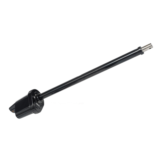
Vehicular swing gate actuator
1500 Series 816 actuator
IMPORTANT!
These instructions apply only to the 816 actuator.
Control box installation/operation is described in a separate control box manual.
www.ApolloGateOpeners.com | (800) 878-7829 | Sales@ApolloGateOpeners.com
Advertisement
Table of Contents

Related Manuals for HySecurity Nice 1500 Series


Summary of Contents for HySecurity Nice 1500 Series
- Page 1 Installation Reference Manual 816 LA Vehicular swing gate actuator 1500 Series 816 actuator IMPORTANT! These instructions apply only to the 816 actuator. Control box installation/operation is described in a separate control box manual. www.ApolloGateOpeners.com | (800) 878-7829 | Sales@ApolloGateOpeners.com...
-
Page 2: Table Of Contents
816 LA Actuator INSTALLATION REFERENCE MANUAL TABLE OF CONTENTS SECTION 1: 816 ACTUATOR OVERVIEW .........3 SECTION 2: INSTALLATION SAFETY ..........4 SECTION 3: TOOLS NEEDED FOR INSTALLATION......4 SECTION 4: ACTUATOR MECHANICAL INSTALLATION....5 SECTION 5: ACTUATOR TO CONTROL BOARD CONNECTIONS..12 5.1 WIRING ACTUATOR TO 936 CONTROL BOARD........13 5.2 WIRING ACTUATOR TO 1050 CONTROL BOARD.........15 5.3 SETTING OPEN/CLOSE LIMITS ..............17 SECTION 6: PART DRAWINGS ............19... -
Page 3: Section 1: 816 Actuator Overview
816 LA Actuator INSTALLATION REFERENCE MANUAL SECTION 1: 816 ACTUATOR OVERVIEW Congratulations on selecting a Nice 816 LA actuator for your gate opener system. With proper selection, sys- tem design, installation, and maintenance this actuator should provide years of reliable operation. This manual covers ONLY the installation of the 816 actuator. -
Page 4: Section 2: Installation Safety
816 LA Actuator INSTALLATION REFERENCE MANUAL SECTION 2: INSTALLATION SAFETY IMPORTANT! • The gate operator installation is NOT a “do-it-yourself” project. Contract a qualified gate operator instal- lation company to install this system to ensure a safe and reliable installation. •... -
Page 5: Section 4: Actuator Mechanical Installation
816 LA Actuator INSTALLATION REFERENCE MANUAL SECTION 4: ACTUATOR MECHANICAL INSTALLATION INSTALL PIVOT ARM TO GATE: PULL-TO-OPEN NOTE: Welding is much 1. Securely mount the pivot arm to the hinge post (IMAGE 1A-1). preferred but Nice offers an 2. If necessary, cut pivot arm for correct placement of the actuator mounting optional bolt-on pivot arm hole. - Page 6 816 LA Actuator INSTALLATION REFERENCE MANUAL INSTALL PIVOT ARM TO GATE: PUSH-TO-OPEN 1. Securely mount the pivot arm to the hinge post (IMAGE 1B-1). NOTE: Welding is much preferred but Nice offers an 2. If necessary, cut pivot arm for correct placement of the actuator mounting optional bolt-on pivot arm hole.
- Page 7 816 LA Actuator INSTALLATION REFERENCE MANUAL MOUNT ACTUATOR TO PIVOT ARM 1. Mount the actuator to the pivot arm as shown (IMAGE 2-1). Note that the washer goes above the ac- tuator flange. 2. Tighten the lock nut to prevent movement or shifting when the actuator is running. This will also pre- vent excessive “bounce”...
- Page 8 816 LA Actuator INSTALLATION REFERENCE MANUAL AFFIX GATE BRACKET TO ACTUATOR ARM If security is of the utmost importance then the bracket may be connected to the actuator arm using the 1/2” x 3” bolt, washer, and lock nut (IMAGE 3-1). However, to enable quick manual opening of the gate in case of power failure, it is recommended to use the quick release hitch pin with R-clip (IMAGE 3-2).
- Page 9 816 LA Actuator INSTALLATION REFERENCE MANUAL 3: AFFIX GATE BRACKET TO ACTUATOR ARM (CONT.) 1/2”x 3” BOLT 1/2” WASHER GATE BRACKET ACTUATOR 1/2” LOCK NUT IMAGE 3-3: GATE BRACKET WITH BOLT, WASHER, NUT HITCH PIN GATE BRACKET ACTUATOR R-CLIP IMAGE 3-4: GATE BRACKET WITH HITCH PIN AND R-CLIP www.ApolloGateOpeners.com | (800) 878-7829 | Sales@ApolloGateOpeners.com...
- Page 10 816 LA Actuator INSTALLATION REFERENCE MANUAL POSITION GATE BRACKET ON GATE 1. Place gate in: a) OPEN position for PULL-TO-OPEN configuration (IMAGE 4-1). b) CLOSED position for PUSH-TO-OPEN configurations ( IMAGE 4-2). 2. With actuator arm fully retracted, rotate entire actuator on the pivot arm around until the gate bracket attached to the actuator is positioned on a supporting structure of gate.
- Page 11 816 LA Actuator INSTALLATION REFERENCE MANUAL AFFIX GATE BRACKET TO GATE 1. Weld the gate bracket to the gate supporting structure (IMAGE 5-1). CAUTION! NEVER WELD PARTS TO THE GATE OR POSTS WHEN THE CONTROL BOARD IS POWERED TO AVOID IRREPAIRABLE DAMAGE TO THE CIRCUIT BOARD! GATE BRACKET CENTERLINE ACTUATOR...
- Page 12 816 LA Actuator INSTALLATION REFERENCE MANUAL RUN ACTUATOR CABLE(S) TO CONTROL BOX Run the cable of the actuator closest to the control box through a hole (with rubber grommet) drilled in the bottom on the control box. If necessary, entry may be made elsewhere on the control box. If a dual gate installation: 1.
-
Page 13: Section 5: Actuator To Control Board Connections
816 LA Actuator INSTALLATION REFERENCE MANUAL SECTION 5: ACTUATOR TO CONTROL BOARD CONNECTIONS REMOVE CONNECTOR FOR WIRING TO 936/1050 When wiring the 816 actuator to the 936 or 1050 control boards, it is necessary to cut off the existing actuator connector and battery wires (IMAGE 7-1). BATTERY LUGS ACTUATOR CONNECTOR... -
Page 14: Wiring Actuator To 936 Control Board
816 LA Actuator INSTALLATION REFERENCE MANUAL 5.1 WIRING ACTUATOR TO 936 CONTROL BOARD 936 CONTROL BOARD WIRING: PULL-TO-OPEN NOTE: If a gate moves in opposite direction from what is expected, reverse the motor power lead wiring (red & black wires) for that motor. - Page 15 816 LA Actuator INSTALLATION REFERENCE MANUAL 936 CONTROL BOARD WIRING: PUSH-TO-OPEN 1. Locate MOTOR 1 and MOTOR 2 connectors on 936 board per IMAGE 8-1. 1. Wire MOTOR 1 connector per IMAGE 9-1 (PUSH-TO-OPEN). 2. If dual gate, wire MOTOR 1 & 2 connectors per IMAGE 9-2 (PUSH-TO-OPEN).. PUSH-TO-OPEN (DUAL GATE) PUSH-TO-OPEN (SINGLE GATE) MOTOR 1...
-
Page 16: Wiring Actuator To 1050 Control Board
816 LA Actuator INSTALLATION REFERENCE MANUAL 5.2 WIRING ACTUATOR TO 1050 CONTROL BOARD 1050 CONTROL BOARD WIRING: PULL-TO-OPEN MOTOR MOTOR NOTE: If a gate moves in opposite direction from what is expected, reverse the motor power lead wiring (red & black wires) for that motor. - Page 17 816 LA Actuator INSTALLATION REFERENCE MANUAL 1050 CONTROL BOARD WIRING: PUSH-TO-OPEN 1. Locate MOTOR 1 and MOTOR 2 connectors on 1050 board per IMAGE 10-1. 1. If single gate, wire MOTOR 1 connector per IMAGE 11-1 (PUSH-TO-OPEN). 2. If dual gate, wire MOTOR 1 & 2 connectors per IMAGE 11-2 (PUSH-TO-OPEN).. MOTOR 1 MOTOR 1 MOTOR 2...
-
Page 18: Setting Open/Close Limits
816 LA Actuator INSTALLATION REFERENCE MANUAL 5.3 SETTING OPEN/CLOSE LIMITS The 816 actuator features two limit screws for adjustment of the actuator open and close limits, and these func- tion as described as follows in INSTRUCTIONS 12 and 13. SETTING MOTOR 1 OPEN/CLOSE LIMITS After connection of actuator and battery leads to the control board, the gate should now open or close when the appropriate button(s) on the control box or control board are pressed. - Page 19 816 LA Actuator INSTALLATION REFERENCE MANUAL After following instructions in INSTRUCTION 12 for adjusting limits of the MOTOR 1 actuator, follow the steps below to set limits for the MOTOR 2 actuator. SETTING MOTOR 2 OPEN/CLOSE LIMITS 1. After setting limits of primary actuator (INSTRUCTION 12), disconnect it from the MOTOR 1 con- nector and plug the secondary actuator harness into the MOTOR 1 connector.
-
Page 20: Section 6: Part Drawings
816 LA Actuator INSTALLATION REFERENCE MANUAL SECTION 6: PART DRAWINGS www.ApolloGateOpeners.com | (800) 878-7829 | Sales@ApolloGateOpeners.com... - Page 21 816 LA Actuator INSTALLATION REFERENCE MANUAL www.ApolloGateOpeners.com | (800) 878-7829 | Sales@ApolloGateOpeners.com...
- Page 22 816 LA Actuator INSTALLATION REFERENCE MANUAL www.ApolloGateOpeners.com | (800) 878-7829 | Sales@ApolloGateOpeners.com...
-
Page 23: Section 7: Warranty
This warranty will be interpreted, construed, and enforced in all respects in the name plate of a manufacturer other than HySecurity or Nice and they are not a accordance with the laws of the State of Washington, without reference to its part of the base model.
Need help?
Do you have a question about the Nice 1500 Series and is the answer not in the manual?
Questions and answers