
Related Manuals for GESTRA TRS 5-50


Summary of Contents for GESTRA TRS 5-50
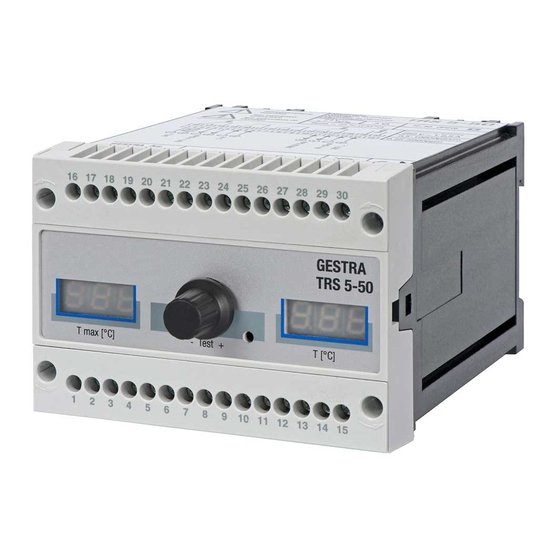
- Page 1 Temperature Switch TRS 5-50 Original Installation Instructions 819226-05 E n g l i s h...
-
Page 2: Table Of Contents
Note on the Declaration of Conformity / Declaration by the Manufacturer ..........6 Functional Safety acc. to IEC 61508 Safety characteristics of the subsystem TRG 5-6.. / TRS 5-50 ..............7 Terms and abbreviations .........................7 Determination of the Safety Integrity Level (SIL) for safety-related systems ..........8 Technical data TRS 5-50 ..............................9... - Page 3 Contents - continued - Page In the plant: Wiring temperature sensor Connection for temperature sensor .......................15 Wiring diagram for temperature sensor ....................15 Factory setting ............................16 Changing factory settings Changing the configuration ........................16 Commissioning procedure Start and adjustment of MAX limit ......................17 Operation, alarm and test Indicators and adjustors ........................18 Troubleshooting...
-
Page 4: Important Notes
Important notes Usage for the intended purpose The temperature switch TRS 5-50 is used in conjunction with temperature sensor TRG 5-6.. as safety temperature limiter or monitor, for instance in steam boilers and (pressurised) hot-water plants. When the max. admissible temperature in the superheater or the inlet line is reached, the safety tem- perature limiter or monitor switches the heating off. -
Page 5: Safety Note
The temperature switch TRS 5-50 in conjunction with temperature sensors TRG 5-6.. is certified to IEC 61508. This standard describes the functional safety of safety-related electrical/electronic/pro- grammable electronic systems. The equipment combination TRG 5-6.. + TRS 5-50 corresponds to a type B subsystem with Safety Integrity Level (SIL) 3. DIN EN 14597 The temperature switch TRS 5-50 in conjunction with temperature sensing electrodes type TRG 5-6.. -
Page 6: Lv (Low Voltage) Directive And Emc (Electromagnetic Compatibility)
The temperature switch TRS 5-50 meets the requirements of the Low Voltage Directive 2014/35/EU and the EMC Directive 2014/30/EU. ATEX (Atmosphère Explosible) According to the European Directive 2014/34/EU the temperature switch TRS 5-50 must not be used in potentially explosive areas. UL / cUL (CSA) Approval The equipment meets the requirements of the Directives: UL 508 and CSA C22.2 No. -
Page 7: Functional Safety Acc. To Iec 61508
This architecture consists of two channels that detect and diagnose faults in each other. If a fault is detected, the equipment combination TRG 5-6.. / TRS 5-50 will go to the safe state, which means that the contacts of both output relays will open the safety circuit. -
Page 8: Determination Of The Safety Integrity Level (Sil) For Safety-Related Systems
Functional safety acc. to IEC 61508 - continued - Determination of the Safety Integrity Level (SIL) for safety-related systems Temperature sensor, temperature switch and actuators (auxiliary contactor in safety circuit) are sub- systems and together constitute a safety-related system that executes a safety function. The specification of the safety-related characteristics Fig. -
Page 9: Technical Data
Technical data TRS 5-50 Supply voltage 24 VDC +/– 20%, 0.3 A; 100-240 VAC + 10/– 15%, 47-63 Hz, 0.2 A Fuse external M 0.5 A Power consumption 7 VA Wiring temperature sensor 1 input for temperature sensor TRG 5-63, TRG 5-64, TRG 5-65, TRG 5-66, TRG 5-67 and TRG 5-68, (platinum resistance thermometer Pt 100 to EN 60751), with 3 poles and screen. -
Page 10: Name Plate / Marking
Technical data - continued - TRS 5-50 - continued - Ambient temperature when system is switched on: 0 ° ... 55 °C during operation: -10 ... 55 °C Transport temperature –20 ... +80 °C (<100 hours), defrosting time of the de-energized equipment before it can be put into operation: 24 hours: 24 hours. -
Page 11: In Control Cabinet: Mounting Temperature Switch
Supporting rail type TH 35, EN 60715 Installation in control cabinet The temperature switch TRS 5-50 is clipped onto the support rail type TH 35, EN 60715 in the control cabinet. Fig. 6 4 Please enter the defined limit value on the nameplate before mounting the equipment. -
Page 12: In Control Cabinet: Wiring Temperature Switch
In control cabinet: Wiring temperature switch Wiring diagram for temperature switch TRS 5-50 (+) (-) 17 18 19 20 21 22 23 24 11 12 ws rt rt ( - ) Fig. 7 Connection of supply voltage Wiring diagram for temperature sensor with fuse 0.5 A (semi-delay) provided on site... -
Page 13: Connection Of Supply Voltage
The equipment is supplied with 24 V DC or 100 - 240 V AC and fused with an external semi-delay fuse 0.5 A. For the supply of the temperature switch TRS 5-50 with 24 V DC use a safety extra-low voltage (SELV) power supply unit. -
Page 14: Connection For Actual-Value Output (Optional)
Do not use this output for activating safety circuits. Attention Fuse the temperature switch TRS 5-50 with an external semi-delay fuse 0.5 A. Any item of equipment that you want to connect to the terminals 6/7, 14/15 and 20/21 of the temperature switch must be electrically isolated from dangerous contact voltages as per DIN EN 61140, e. -
Page 15: In The Plant: Wiring Temperature Sensor
In the plant: Wiring temperature sensor Connection for temperature sensor The temperature switch TRS 5-50 is designed for use in conjunction with temperature sensors TRG 5-63, TRG 5-64, TRG 5-65, TRG 5-66, TRG 5-67 and TRG 5-68. To connect the equipment use screened multi-core control cable with a min. conductor size 0.5 mm e. -
Page 16: Factory Setting
Factory setting Temperature Switch TRS 5-50 MAX limit = 25 °C Reset hysteresis: -3 K (fixed setting) Configuration: Safety temperature monitor Code switch c : S1, S2 OFF Changing factory settings Danger The upper terminal strip of the equipment is live during operation. -
Page 17: Commissioning Procedure
Commissioning procedure Start and adjustment of MAX limit Indication of actual value / error code Fig. 10 Indication of Rotary button with Pushbutton (hidden) for limit value integrated push- enabling the setting. Hole 3 mm ∅ button Start Status and action Display Function All segments and decimal points... -
Page 18: Operation, Alarm And Test
Operation, alarm and test Indicators and adjustors Indication of actual value / error code Fig. 10 Indication of Rotary button with Pushbutton (hidden) for limit value integrated push- enabling the setting. Hole 3 mm ∅ button Operation Status and action Display Function Display T... -
Page 19: Troubleshooting
Troubleshooting Indication, diagnosis and remedy Attention Before carrying out the fault diagnosis please check: Supply voltage: Is the equipment supplied with the voltage specified on the name plate? Wiring: Is the wiring in accordance with the wiring diagram? Faults indicated by the seven-segment display on the right side Error code Error Remedy... -
Page 20: Measure Fluid Temperature
Troubleshooting - continued - Measure fluid temperature Use table Fig. 11 to ascertain the current temperature of the fluid via the resistance value of the Pt 100 directly on the temperature sensor. Please follow the instructions given in the installation & operating manual for the TRG 5-6x. °C Ω/deg 100.00 103.90 107.79 111.67 115.54 119.40 123.24 127.07 130.89 134.70 138.50 0.385... -
Page 21: Further Notes
Further Notes Action against high frequency interference High frequency interference can occur for example as a result of out-of-phase switching operations. Should such interference occur and lead to sporadic failures, we recommend the following actions in order to suppress any interference. Provide inductive loads with RC combinations according to manufacturer's specification to ensure interference suppression. - Page 22 For your Notes...
- Page 23 For your Notes...
- Page 24 Agencies all over the world: www.gestra.de GESTRA AG Münchener Straße 77 28215 Bremen Germany Telefon +49 421 3503-0 Telefax +49 421 3503-393 E-mail info@de.gestra.com www.gestra.de 819226-05/06-2017cm (808885-06) · GESTRA AG · Bremen · Printed in Germany...
Need help?
Do you have a question about the TRS 5-50 and is the answer not in the manual?
Questions and answers