
Subscribe to Our Youtube Channel
Related Manuals for GESTRA TRS 5-52


Summary of Contents for GESTRA TRS 5-52
- Page 1 Temperature Switch TRS 5-52 Original Installation Instructions 819175-04 E n g l i s h...
-
Page 2: Table Of Contents
Key .................................8 Installation in control cabinet ........................8 Name plate / marking ..........................9 In control cabinet: Wiring temperature switch Wiring diagram for temperature switch TRS 5-52 .................10 Key ...............................10 Connection for supply voltage .......................11 Connection for output contacts ......................11 Connection for temperature sensor .......................11 Connection for actual-value output (optional) ..................11... - Page 3 Contents - continued - Page Operating temperature switch Key to codes on seven-segment display ....................13 Parameter setting ..........................14 Commissioning procedure Setting switchpoints and actual-value output ..................15 Operation, alarm and test Indications ............................16 Checking functions of MIN / MAX output contacts .................16 Troubleshooting Indication, diagnosis and remedy ......................17 Further notes...
-
Page 4: Important Notes
Any error or malfunction that occurs in the temperature sensor, the electrical connection or the settings is indicated by the seven-segment LED display and will trigger a MIN and MAX alarm. If an error occurs in the temperature switch TRS 5-52, only the MIN and MAX alarm is raised and the system is restarted. -
Page 5: Directives And Standards
Directives and Standards DIN EN 14597 The temperature switch TRS 5-52 in conjunction with temperature sensor TRG 5-.. is type-approved to DIN EN 14597. DIN EN 14597 describes and specifies - among other things - the requirements made on tests of temperature monitors. -
Page 6: Technical Data
Technical data TRS 5-52 Supply voltage 24 VDC +/– 20 % Fuse external 0.5 A (semi-delay) Power consumption 4 VA Wiring temperature sensor 1 input for temperature sensor TRG 5-63, TRG 5-64, TRG 5-65, TRG 5-66, TRG 5-67 and TRG 5-68, (platinum resistance thermometer Pt 100 to EN 60751), with 3 poles and screen. -
Page 7: Scope Of Supply
DIN Registration number DIN TW 1232 (see name plate) UL /cUL (CSA) Approval Approval UL 508 and CSA C22.2 No. 14-13, Standards for Industrial Control Equipment. File E243189. Scope of supply TRS 5-52 1 Temperature switch TRS 5-52 1 Installation & operating manual... -
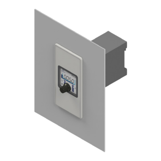
Page 8: In Control Cabinet: Mounting Temperature Switch
Upper terminal strip Body Lower terminal strip Supporting rail type TH 35, EN 60715 Installation in control cabinet The temperature switch TRS 5-52 is clipped onto the support rail type TH 35, EN 60715 in the control cabinet. Fig. 1 4... -
Page 9: Name Plate / Marking
In control cabinet: Mounting temperature switch - continued - Name plate / marking Name plate (on top) Safety note Type designation Manufacturer Protection External fuse for output contacts Ambient temperature Output contacts Name plate (at the bottom) Connection for actual-value output (optional) Fuse, provided on site Connection for temperature sensor... -
Page 10: In Control Cabinet: Wiring Temperature Switch
In control cabinet: Wiring temperature switch Wiring diagram for temperature switch TRS 5-52 16 17 18 19 20 21 22 23 1 2 3 4 5 6 7 8 ws rt M 0.5 A (semi-delay) (+) (-) Fig. 3 Connection of supply voltage 24 V DC with fuse 0.5 A (semi-delay) provided on site Temperature sensor TRG 5-.. -
Page 11: Connection For Supply Voltage
In control cabinet: Wiring temperature switch - continued - Connecting supply voltage The equipment is supplied with 24 V DC and fused with an external slow-blow fuse 0.5 A. Please use a safety power supply unit with safe electrical isolation. The power supply unit must be electrically isolated from dangerous contact voltages and must meet at least the requirements on double or reinforced isolation according to one of the following standards: DIN EN 50178, DIN EN 61010-1, DIN EN 60730-1 or DIN EN 60950. -
Page 12: In The Plant: Wiring Temperature Sensor
In the plant: Wiring temperature sensor Connecting temperature sensor The temperature switch TRS 5-52 is designed for use in conjunction with temperature sensors TRG 5-63, TRG 5-64, TRG 5-65, TRG 5-66, TRG 5-67 and TRG 5-68. To connect the equipment use screened multi-core control cable with a min. conductor size 0.5 mm e. -
Page 13: Operating Temperature Switch
Operating temperature switch Key to codes on seven-segment display OO75 Seven-segment display MAX LED Rotary button with integrated MIN LED push-button Fig. 5 Code Description Indicated when rotary button is turned to the right: AL.Hi Alarm High MAX switchpoint AL.Lo Alarm Low MIN switchpoint Sout... -
Page 14: Parameter Setting
Operating temperature switch - continued - Setting parameters OO75 Seven-segment display MAX LED Rotary button with integrated MIN LED push-button Fig. 5 Start Activity Display Function Seven-segment display shows equipment and software System test, takes approx. 3 sec. Switch on supply voltage. version. -
Page 15: Commissioning Procedure
Commissioning procedure Setting switchpoints and actual-value output Setting MIN/MAX switchpoints Activity Function Select parameter AL.Lo, set the desired temperature MIN switchpoint setting between 0 - 600 °C. and save the setting. Select parameter AL.HI, set the desired temperature MAX switchpoint setting between 0 - 600 °C. and save the setting. -
Page 16: Operation, Alarm And Test
Operation, Alarm and Test Indicators Operation Activity Display Function Temperature between MIN MIN and MAX LEDs are not MIN output contact 16/18 open, 17/18 closed. and MAX. illuminated. MAX output contact 21/23 open, 22/23 closed. MIN alarm Value below switchpoint MIN MIN LED illuminated red MIN output contact 16/18 closed, 17/18 open. -
Page 17: Troubleshooting
Troubleshooting Indication, diagnosis and remedy Attention Before carrying out the fault diagnosis please check: Supply voltage: Is the equipment supplied with the mains voltage specified on the name plate? Wiring: Is the wiring in accordance with the wiring diagram? Faults indicated by the seven-segment display Error code Error Remedy... -
Page 18: Further Notes
Further Notes Action against high frequency interference High-frequency interference can be caused by out-of-phase switching operations. Should sporadic failures or malfunctions occur take the following remedial actions in order to suppress interference: Provide inductive loads with RC combinations according to manufacturer's specification to ensure interference suppression. - Page 19 For your Notes If faults occur that are not listed above or cannot be corrected, please contact our service centre or authorized agency in your country.
- Page 20 Agencies all over the world: www.gestra.de GESTRA AG Münchener Straße 77 28215 Bremen Germany Telefon +49 421 3503-0 Telefax +49 421 3503-393 E-mail info@de.gestra.com www.gestra.de 819175-04/05-2017cm (808880-04) · GESTRA AG · Bremen · Printed in Germany...
Need help?
Do you have a question about the TRS 5-52 and is the answer not in the manual?
Questions and answers