IKA ICC control Manual
Hide thumbs
Also See for ICC control:
- Manual (18 pages) ,
- Operating instructions manual (20 pages) ,
- Operating instructions manual (23 pages)
Table of Contents
Advertisement
Quick Links
Advertisement
Table of Contents

Subscribe to Our Youtube Channel
Related Manuals for IKA ICC control


Summary of Contents for IKA ICC control
- Page 1 20000004067a ICC control_092017 ® ICC control...
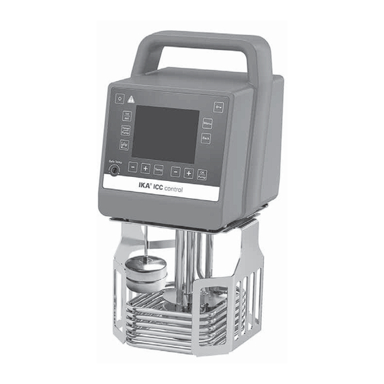
- Page 2 Fig. 1 Fig. 2 Item Designation Operator panel and display Mains switch Power socket Buoyage Heater Stand Pt 100 + Pt 1000 temperature sensor Handle RS 232 port USB port Clamp Cable clip External temperature sensor socket...
-
Page 3: Table Of Contents
Range of use (indoor use only) ..........................7 Unpacking ..............................7 Unpacking ................................7 Delivery scope ...............................7 Preparations ..............................7 Setting up ................................7 Filling and draining ..............................7 Fluid (Standard information for IKA ® fluid......................8 Operator panel and display ........................9 Commissioning ............................10 Setting the safety temperature .......................11 Operation ..............................11 Working screen at the time of delivery .........................11... -
Page 4: Declaration Of Conformity
Declaration of Conformity We declare under our sole responsibility that this product corresponds to the regulations 2014/35/EU, 2006/42/EC, 2014/30/EU and 2011/65/EU and conforms with the standards or standardized documents: EN 61010-1, EN 61010-2-010, EN 61010-2-051, EN 61326-1, EN 60529, DIN 12876-1 and EN ISO 12100. Explication of warning symbols Indicates an imminently hazardous situation, which, if not avoided, will result in death, seri- DANGER... -
Page 5: Safety Instructions
• Be careful when filling a hot bath. explosions or comprehensive monitoring equipment. • Process pathogenic material only in closed vessels under At high operating tempera- a suitable fume hood. Please contact IKA ® application WARNING tures, the temperature of hous- support if you have any question. -
Page 6: Fluids
It is dangerous to touch the • Continuous monitoring of the bath and the filling level of WARNING heater. The temperature of the the bath fluid is required, especially at high temperatures. heater can be very high. • To ensure a sufficient fluid circulation, the viscosity of the bath fluid must not exceed of 50mm /s at the lowest •... -
Page 7: Correct Use
- If the device is operated with accessories that are not Range of use (indoor use only): ®. supplied or recommended by the IKA - Laboratories - Schools - If the device is operated improperly or in contrary to the... -
Page 8: Fluid
• Fluid (Standard information for IKA ® fluid): ® Operating temperature Operating temperature Safety temperature Flash point Designation range for open bath range for closed bath (°C) (°C) application applications (°C) (°C) CF.EG28.N10.80.8 -10 ... 80 -10 … 80 CF.EG39.N20.80.16 -20 …... -
Page 9: Operator Panel And Display
Operator panel and display Fig. 3 Item Designation Function ON/OFF button: Switch on/off the circulator. Adjust the safety temperature limit with delivered screwdriver. Adjustable safety circuit: Start/stop the heating function. “Temp” button: “Temp (+)” button: Increase the temperature setting value. “Temp (-)”... -
Page 10: Commissioning
In working status, stop the pump function by pressing the Circulator “OK/Pump“ button (G). The heating function and pump ICC control stops. Version 1.2.008 In standby status, press the “OK/Pump“ button (G) to Fig. -
Page 11: Setting The Safety Temperature
Setting the safety temperature Adjust the safety temperature with screwdriver included The safety temperature setting will appear on the display. with the device. Factory setting: maximum value Fig. 7 Adjustment range: 0 – 160 °C Note: The safe temperature limit must always be set to at least 25 ºC lower than the flash point of the fluid used. -
Page 12: Menu Navigation And Structure
• Menu navigation and structure: Menu navigation Press the "Menu" key (J). Select the menu option by pressing the “Pump (+)” button (H) or “Pump (-)” button (I). Open the menu item by pressing the "OK/Pump" button (G). Press the “Pump (+)” button (H) or “Pump (-)” button (I) to select the desired menu option and edit the values or settings. - Page 13 Menu structure: Factory Settings TEMPERING Control Control Mode Internal (int) activated External (ext) Control Parameters Automatic Accurate activated Fast Manual Internal (Kp, Ti, Td, Ts, Prop_Bp, Prop_Bn) 60.0, 5.0, 0.3, 3 s, +1.00 K, -1.00 k External (Kp, Ti, Td, Ts, Prop_Bp, Prop_Bn) 1.0, 15.0, 0.0, 90 s, +1.00 K, -1.00 k Information (Kp, Ti, Td, Ts, Prop_Bp, Prop_Bn) Fluids...
-
Page 14: Menu (Details)
• Menu (Details): Fluids: Under the option "Fluids", a variety of heat transfer fluids can be selected. TEMPERING: The selected fluid limits the setting range of the target Control: temperature. See table in the section “Fluids“. The maximum and minimum temperature values of the Control Mode: selected fluid can be set within these limitations. - Page 15 Loop Count: Indicates the total number of loop cycles MODE until program end. Operating Mode A: Note: At the end of the program all device functions are After power-on/power failure no automatic restart of switched off. functions. Edit: Operating Mode B: Edit/change program parameters.
-
Page 16: Interface And Output
- Transmission speed: 9600 bit/s. - Data flow control: none USB device drivers: - Access procedure: data transfer from the stirrer machine to First, download the latest driver for IKA ® devices with USB the computer takes place only at the computer’s request. - Page 17 1.1). The NAMUR commands and the additional specific IKA ® co mmands serve only as low level commands for communication between the device and the PC.
-
Page 18: Maintenance And Cleaning
- Serial number, see type plate Cleaning - Item and designation of the spare part, Disconnect main plug prior to see www.ika.com, spare parts diagram and spare parts list. cleaning! - Software version. Use only cleaning agents which have been approved by Repair ®... -
Page 19: Error Codes
Error codes Any malfunctions during operation will be identified by an error message on the display. Proceed as follows in such cases: Switch off device using the main switch at the back of the device Carry out corrective measures Restart device Error code Effect Cause... -
Page 20: Accessories
Samll cover (for IB eco 8, IB pro 9) CM.ICC Medium cover (for IB pro 12) Large cover (for IB eco 18, IB pro 20) CL.ICC • Additional accessories Pump set PCS.ICC Pt 100.3 Temperature sensor PC 1.1 Cable (RS 232) ® Labworldsoft See more accessories on www.ika.com. -
Page 21: Technical Data
Technical data Nominal voltage 230 ± 10 % / 115 ± 10 % / 100 ± 10 % Frequency 50 / 60 Max. input Power 2100 (230 VAC) / 1100 (115 VAC) / 860 (100 VAC) Working temperature range (RT+10 °C at 1000rpm) °C RT + 10 ... -
Page 22: Warranty
Warranty In accordance with IKA ® warranty conditions, the war- The warranty does not cover worn out parts, nor does it ranty period is 24 months. For claims under the warranty apply to faults resulting from improper use, insufficient please contact your local dealer. You may also send the...
Need help?
Do you have a question about the ICC control and is the answer not in the manual?
Questions and answers