ST STM32 User Manual
Hide thumbs
Also See for STM32:
- User manual (85 pages) ,
- Application note (49 pages) ,
- Quick start manual (31 pages)
Table of Contents
Advertisement
Quick Links
Download this manual
See also:
User Manual
1
Introduction
This user manual describes the STarGrid powerline modem, the latest family of powerline
modems from STMicroelectronics™. The powerline modem itself, although a powerful
device, always needs an external superior system which it uses in order to exchange
information with another node, where another powerline modem and superior system can
be found.
There are various superior systems and this document deals with the hardware
interconnection to powerline modems. These superior systems are from very simple 32-bit
microcontroller boards running standalone firmware to very complex 32-bit micro processor
units running operating systems. This document describes the possible ways of
interconnection and available HW and SW tools for building the system consisting of the
STM32 or SPEAr3xx, and powerline communication coming from the ST7570, 80, and 90
STarGrid family.
The related demonstration boards are:
■
STEVAL-PCC012V1
■
STM3210C-EVAL
■
EVALSPEAr310
■
EVALSPEAr320PLC
■
EVALSPEAr320HMI
■
EVALST7570, 7570-1 KIT, 7580-1, 7590-1.
April 2011
Hardware interconnection of the STM32™,
Doc ID 18303 Rev 1
User manual
SPEAr™3xx, and ST75xx
UM1038
1/24
www.st.com
Advertisement
Table of Contents

Subscribe to Our Youtube Channel
Related Manuals for ST STM32


Summary of Contents for ST STM32
-
Page 1: Introduction
This document describes the possible ways of interconnection and available HW and SW tools for building the system consisting of the STM32 or SPEAr3xx, and powerline communication coming from the ST7570, 80, and 90 STarGrid family. -
Page 2: Table Of Contents
STM32 (STEVAL-PCC012V1) and EVALST7590-1 ....7 STM32 (STM3210C-EVAL) + EVALST7590-1 ..... . 9 SPEAr320 and EVALST7590-1 . - Page 3 UM1038 List of tables List of tables Table 1. Interconnection of demonstration boards EVALST7570 and STEVAL-PCC012V1 ..6 Table 2. Interconnection of demonstration boards EVALST7590 and STEVAL-PCC012V1 ..8 Table 3.
- Page 4 Connectors interconnection - 14-pin STM32 ........
-
Page 5: Stm32 (Steval-Pcc012V1) And Evalst7570-1
UM1038 STM32 (STEVAL-PCC012V1) and EVALST7570-1 STM32 (STEVAL-PCC012V1) and EVALST7570-1 The demonstration boards necessary to connect the STM32 and ST7590 boards and their configuration: STEVAL-PCC012V1 ● Flash the correct firmware into STM32. ● Configure the board according to Figure EVALST7590-1 ●... -
Page 6: Table 1. Interconnection Of Demonstration Boards Evalst7570 And Steval-Pcc012V1
RxD <-- TX 18 (RxD) 2 (TX) Green T_REQ 15 (GPIO3) 11 (MDM_RES) Purple +3.3 V Not connected 13, 14 Black Figure 4. Connectors interconnection - 14-pin STM32 Figure 5. Connectors interconnection - 20-pin ST7570 6/24 Doc ID 18303 Rev 1... -
Page 7: Stm32 (Steval-Pcc012V1) And Evalst7590-1
UM1038 STM32 (STEVAL-PCC012V1) and EVALST7590-1 STM32 (STEVAL-PCC012V1) and EVALST7590-1 The demonstration boards necessary to connect the STM32 and ST7590 boards and their configuration: STEVAL-PCC012V1 ● Flash the correct firmware into STM32. ● Configure the board according to Figure EVALST7590-1 ●... -
Page 8: Table 2. Interconnection Of Demonstration Boards Evalst7590 And Steval-Pcc012V1
1. Possible collision with SD Card™ (if inserted), Wi-Fi (if assembled), MEMS analog (if SPI signal used by R63, R64 with zero value), MEMS digital (if plugged). Figure 9. Connectors interconnection - 14-pin STM32 and 14-pin ST7590 1. See paragraph Appendix... -
Page 9: Stm32 (Stm3210C-Eval) + Evalst7590-1
+5 V (or +3.3 V) (pin 4) GND (CN8 - pin 50) Black GND (pin 14) STM32 UART TX (CN9 - pin 12 - PD8) Green ST7590 RX (pin 2) STM32 UART RX (CN9 - pin 8 - PD9) Blue ST7590 TX (pin 1) Table 4. -
Page 10: Spear320 And Evalst7590-1
SPEAr320 and EVALST7590-1 UM1038 SPEAr320 and EVALST7590-1 Figure 10. SPEAr320 and EVALST7590-1 The demonstration boards necessary to connect the EVALSPEAr320 and EVALST7590 boards and their configuration: EVALSPEAr320 ● Interconnect PC with UART1. ● Interconnect Ethernet to network. ● Plug Flash disk with correct SW into the first USB, use the file system of this USB. -
Page 11: Evalspear310 And Evalst7590-1 Via Rs232
UM1038 EVALSPEAr310 and EVALST7590-1 via RS232 EVALSPEAr310 and EVALST7590-1 via RS232 Figure 11. EVALSPEAr310 and EVALST7590-1 via RS232 The demonstration boards necessary to connect the SPEAr310 and ST7590 boards and their configuration: EVALSPEAr310 ● Interconnect PC with UART1. ● Interconnect Ethernet to network. ●... -
Page 12: Figure 12. Steval-Pcc001V1
EVALSPEAr310 and EVALST7590-1 via RS232 UM1038 Figure 12. STEVAL-PCC001V1 12/24 Doc ID 18303 Rev 1... -
Page 13: Spear3Xx And St7570, St7580, St7590 Via Usb
UM1038 SPEAr3xx and ST7570, ST7580, ST7590 via USB SPEAr3xx and ST7570, ST7580, ST7590 via USB Figure 13. EVALSPEAr3xx and ST7570, ST7580, ST7590 via USB The demonstration boards necessary to connect the SPEAr3xx and ST7590 boards and their configuration: EVALSPEAr3xx: ● Interconnect PC with UART1. -
Page 14: Evalspear320Hmi And St7570, St7580, St7590 Via Uart
EVALSPEAr320HMI and ST7570, ST7580, ST7590 via UART UM1038 EVALSPEAr320HMI and ST7570, ST7580, ST7590 via UART Figure 14. EVALSPEAr320HMI and ST7570, ST7580, ST7590 via UART The demonstration boards necessary to connect the EVALSPEAr3xx with the ST7570/80/90 board and their configuration: EVALSPEAr3xx ●... -
Page 15: Table 6. Evalspear320Hmi, Unified Plm Connector Cn704 (St7570/80/90)
UM1038 EVALSPEAr320HMI and ST7570, ST7580, ST7590 via UART Table 6. EVALSPEAr320HMI, unified PLM connector CN704 (ST7570/80/90) Signal ST7570 + 80/90 Color notation TxD --> RX 3 (TxD) 3 (RX) Blue RxD <-- TX 5 (RxD) 5 (TX) Green Auxiliary IO1 7 (TREQ / RTS) 7 (PL GPIO39) Purple... -
Page 16: Appendix Ahw Images
HW images UM1038 Appendix A HW images STM32 (STEVAL-PCC012V1) and EVALST7570-1 Figure 16. ST7570 and STEVAL-PCC012V1 16/24 Doc ID 18303 Rev 1... -
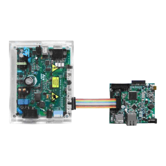
Page 17: Stm32 (Steval-Pcc012V1) And Evalst7590-1
UM1038 HW images STM32 (STEVAL-PCC012V1) and EVALST7590-1 Figure 17. ST7590 and STEVAL-PCC012V1 STM32 (STM3210C-EVAL) and EVALST7590-1 Figure 18. ST7590 and STM3210C-EVAL Doc ID 18303 Rev 1 17/24... -
Page 18: Spear320 And Evalst7590-1
HW images UM1038 SPEAr320 and EVALST7590-1 Figure 19. SPEAr320 and EVALST7590-1 SPEAr310 and EVALST7590-1 via RS232 Figure 20. SPEAr310 and EVALST7590-1 via RS232 18/24 Doc ID 18303 Rev 1... -
Page 19: Any Spear3Xx And St7570, St7580 Or St7590 Via Usb
UM1038 HW images Any SPEAr3xx and ST7570, ST7580 or ST7590 via USB Figure 21. Any SPEAr3xx and ST7570, ST7580 or ST7590 via USB Doc ID 18303 Rev 1 19/24... -
Page 20: Evalspear320Hmi And St7570, St7580, St7590 Via Uart
HW images UM1038 EVALSPEAr320HMI and ST7570, ST7580, ST7590 via UART Figure 22. SPEAr320HMI and ST7570 via the unified connector, UART 20/24 Doc ID 18303 Rev 1... -
Page 21: Appendix B Additional Schematics
UM1038 Additional schematics Appendix B Additional schematics STEVAL-PCC001V1 Figure 23. STEVAL-PCC001V1 schematic Doc ID 18303 Rev 1 21/24... -
Page 22: Extension Connectors At Spear320Hmi Board
Additional schematics UM1038 Extension connectors at SPEAr320HMI board Figure 24. SPEAr320HMI, CN701 Figure 25. SPEAr320HMI, CN702 22/24 Doc ID 18303 Rev 1... -
Page 23: Appendix C Endnotes
EVALST7590-1 board. (The FTDI chip should be also in reset when not connected to USB). This interconnection does not implement signals for asynchronous communication from ST7590 to STM32. Revision history Table 7. - Page 24 No license, express or implied, by estoppel or otherwise, to any intellectual property rights is granted under this document. If any part of this document refers to any third party products or services it shall not be deemed a license grant by ST for the use of such third party products or services, or any intellectual property contained therein or considered as a warranty covering the use in any manner whatsoever of such third party products or services or any intellectual property contained therein.
Need help?
Do you have a question about the STM32 and is the answer not in the manual?
Questions and answers