Table of Contents
Advertisement
Advertisement
Table of Contents

Related Manuals for HT EQUITEST 5071


Summary of Contents for HT EQUITEST 5071
- Page 1 Copyright HT ITALIA 2013 Versione EN 1.00 - 15/01/2013...
-
Page 3: Table Of Contents
EQUITEST 5071 Table of contents PRECAUTIONS AND SAFETY MEASURES ..............2 1.1. Preliminary instructions ......................2 1.2. During use ..........................3 1.3. After use ..........................3 Definition of measurement (overvoltage) category ................. 3 GENERAL DESCRIPTION ....................4 ... -
Page 4: Precautions And Safety Measures
EQUITEST 5071 1. PRECAUTIONS AND SAFETY MEASURES The instrument has been designed in compliance with Standards IEC/EN61557 and IEC/EN 61010-1 relevant to electronic measuring instruments. CAUTION For your safety and in order to prevent damaging the instrument, please carefully follow the procedures described in this manual and read all notes preceded by the symbol with the utmost attention. -
Page 5: During Use
EQUITEST 5071 1.2. DURING USE Please carefully read the following recommendations and instructions: CAUTION Failure to comply with the caution notes and/or instructions may damage the instrument and/or its components or be a source of danger for the operator. Before activating the rotary switch, disconnect the test leads from the circuit under test. -
Page 6: General Description
EQUITEST 5071 2. GENERAL DESCRIPTION Instrument EQUITEST 5071 carries out the following measurements: LOW: Continuity test of protective conductors with test current of 200mA in compliance with standard IEC/EN61557-4 LOW10A: Continuity test of protective conductors with test current of 10A in compliance with standard IEC/EN60439-1 ... -
Page 7: Instrument Description
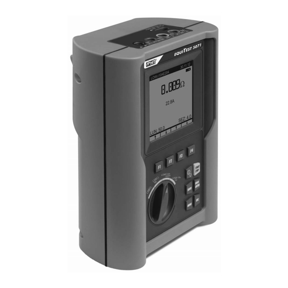
EQUITEST 5071 4. INSTRUMENT DESCRIPTION 4.1. FRONT PANEL CAPTION: 1. LCD display 2. F1, F2, F3, F4 keys 4. START/STOP key 5. HOLD/ENTER key 6. SAVE key 7. ESC key 8. MENU key 9. Rotary selector switch Fig. 1: Description of the instrument’s front panel 4.2. -
Page 8: Description Of Function Keys
EQUITEST 5071 4.3. DESCRIPTION OF FUNCTION KEYS Description Key to switch on/off the instrument. Press and hold the key for some seconds to turn off the instrument. Shortly press this key to activate display backlighting. Keys for programming the internal parameters associated with F1, F2, F3, F4 the functions of the instrument. -
Page 9: Backlight
EQUITEST 5071 4.6. BACKLIGHT During instrument operation, a further short pressing of the key turns on the display’s backlighting. In order to save battery efficiency, backlighting automatically turns off after approx. 5 seconds. A frequent use of backlighting reduces the batteries’ life. -
Page 10: Adjusting Date And Time
EQUITEST 5071 5.2. ADJUSTING DATE AND TIME Proceed as follows: 1. Press the MENU key with the selector switch in any position to enter the General Menu. 2. Use the F1 key to move the cursor to “DATE&TIME”. Confirm with ENTER. The following screen appears on the display: DATE&TIME... -
Page 11: Operating Instructions
EQUITEST 5071 6. OPERATING INSTRUCTIONS 6.1. LOW: CONTINUITY OF PROTECTIVE CONDUCTORS WITH 200mA Measurement is carried out in compliance with standard IEC/EN61557-4. CAUTION Before carrying out the continuity test, make sure there is no voltage at the ends of the conductor to be analyzed. -
Page 12: Calibration Of Measuring Cables
EQUITEST 5071 6.1.1. Calibration of measuring cables 1. Insert the black cable and the blue cable into the relevant input terminals B1 and B4 of the instrument. Fig. 3: Terminal connection during calibration procedure 2. If, for the measurement to be carried out, the length of the cables provided should be insufficient, extend the blue cable. -
Page 13: Measuring
EQUITEST 5071 6.1.2. Measuring 1. Select the desired mode using the F1 key. 2. Insert the black cable and the blue cable into the relevant input terminals B1 and B4 of the instrument: Fig. 4: Instrument connection for LOW test 3. - Page 14 EQUITEST 5071 "AUTO" mode results At the end of the test, in LOW 30.11.12 Average value resistance Ravg case the average value resistance Ravg 1.05 measured is lower than 5, the instrument gives out a double sound to 1.07...
-
Page 15: Anomalous Situations In "Auto", "Rt+", "Rt-" Mode
EQUITEST 5071 6.1.2.1. Anomalous situations in "AUTO", "RT+", "RT-" mode If the instrument detects LOW 30.11.12 a voltage higher than -.- - approx. 15V at the input terminals, the message test cannot carried because to the side appears on... -
Page 16: Low10A: Continuity Of Protective Conductors With 10A
EQUITEST 5071 6.2. LOW10A: CONTINUITY OF PROTECTIVE CONDUCTORS WITH 10A Measurement is carried out in compliance with standards IEC/EN60439-1. Measurement is carried out by voltammetric method with 4 wires. Therefore, the calculated value is not influenced by the value of resistance of the measuring cables, so it is not necessary to carry out any preventive calibration of the cables used for measuring (unlike with function LOW). - Page 17 EQUITEST 5071 Fig. 5: Instrument connection for LOW10A test 5. Press the START key. The instrument starts testing. CAUTION When message "MEASURING…" is displayed, this indicates that the instrument is carrying out the test. Never disconnect the instrument’s leads during this phase.
-
Page 18: Anomalous Situations
EQUITEST 5071 6.2.2. Anomalous situations LOW 10A If the instrument does not 31.11.12 detect any power supply at connector "230V 50Hz", ----- it displays the message reported to the side. ----A NO POWER SUPPLY RLIM=0.100 ... -
Page 19: Low10Ae204: Continuity 10A In Compliance With Iec/En60204-1:2006
EQUITEST 5071 6.3. LOW10AE204: CONTINUITY 10A IN COMPLIANCE WITH IEC/EN60204- 1:2006 Measurement is carried out in compliance with standard IEC/EN60204-1:2006, which states that measurement result must be compatible with the protective conductor’s length, section and material. The instrument evaluates the limit threshold of measured resistance according to the following formula: ... -
Page 20: Measuring
EQUITEST 5071 6.3.1. Measuring 1. Turn the rotary switch to LOW10AE204. The following screen appears on the display: LOW10AE204 30.11.12 ----- ----A LEN: 10.0 SEC: 4.0 2. Use the F1 and F2 keys to set the length in range 0.1m 999.9m and keys F3 and F4 to set the section of the protective conductor being tested, selecting the values 0.5, 1,... - Page 21 EQUITEST 5071 5. Press the START key. The instrument starts testing. CAUTION When message "MEASURING…" is displayed, this indicates that the instrument is carrying out the test. Never disconnect the instrument’s leads during this phase. LOW 10A At the end of the test, the 31.11.12...
-
Page 22: Anomalous Situations
EQUITEST 5071 6.3.2. Anomalous situations If the instrument does not LOW10AE204 30.11.12 detect any power supply at connector "230V 50Hz", ----- it displays the message reported to the side. ----A NO POWER SUPPLY LEN: 10.0 SEC: 4.0 ... -
Page 23: Loop/Ra : Loop Impedance, Overall Earth Resistance And Phase Sequence
EQUITEST 5071 6.4. LOOP/RA LOOP IMPEDANCE, OVERALL EARTH RESISTANCE AND PHASE SEQUENCE Measurement is carried out in compliance with standards IEC/EN61557-3 and IEC/EN60204-1:2006. Turn the rotary switch to LOOP/Ra With the F1 key it is possible to select one of the following measuring modes (which cyclically appear when pressing the key): ... -
Page 24: High-Resolution Impedance Measurement (0.1 M)
ICAL For any detail regarding the use and the technical specifications of accessory IMP57, please refer to the relevant user manual or visit the website www.ht-instruments.com. 6.4.2. "P-N" mode: measurement procedure and results 1. Select the P-N mode using the F1 key. - Page 25 EQUITEST 5071 CAUTION The following test entails the circulation of a maximum current of approx. 6A between phase and neutral. This could cause the tripping of possible magnetothermal protections with lower tripping currents. In this case, carry out the measurement upstreams of the protections.
-
Page 26: P-P" Mode: Measurement Procedure And Results
EQUITEST 5071 6.4.3. "P-P" mode: measurement procedure and results 1. Select the P-P mode using the F1 key. 2. Insert the 3 Black, Green, Blue connectors of the separate cables into the relevant instrument input terminals B1, B3, B4. Fig. 9: Instrument connection for measuring Phase-Phase impedance 3. -
Page 27: P-Pe" Mode: Measurement Procedure And Results
EQUITEST 5071 6.4.4. "P-PE" mode: measurement procedure and results 1. Select the P-PE mode using the F1 key. 2. Insert the 3 Black, Green, Blue connectors of the shuko cable or of the separate cables into the relevant instrument input terminals B1, B3, B4 (see Fig. 10, Fig. 11, Fig. 12). In case separate cables are used, insert alligator clips on the free cable ends. - Page 28 EQUITEST 5071 At the end of the test, the instrument gives out LOOP 30.11.12 a double sound to Value Phase-Earth impedance expressed in . indicate that test has 1.07 been correctly performed Value of the assumed Phase- 215A following...
-
Page 29: Mode: Measurement Procedure And Results
EQUITEST 5071 6.4.5. "R " mode: measurement procedure and results 1. Select the R mode using the F1 key. 2. Insert the 3 Black, Green, Blue connectors of the shuko cable or of the separate cables into the relevant instrument input terminals B1, B3, B4 (see Fig. 13, Fig. 14, Fig. 15). In case separate cables are used, insert alligator clips on the free cable ends. - Page 30 EQUITEST 5071 LOOP 30.11.12 At the end of the test, Value Phase-Earth resistance expressed in the instrument gives out 1.07 a double sound to indicate that test has 215A Value of the assumed Phase- been correctly Earth short-circuit...
-
Page 31: Mode: Measurement Procedure And Results
EQUITEST 5071 6.4.6. " " mode: measurement procedure and results 1. Select the " " mode using the F1 key. 2. Insert the 3 Black, Blue, Green connectors of the separate cables into the relevant instrument input terminals B1, B2, B3. -
Page 32: Anomalous Situations In "P-P", "P-N", "P-Pe","R
EQUITEST 5071 6.4.6.1. Anomalous situations in "P-P", "P-N", "P-PE","R ", " " mode If the instrument detects LOOP 30.11.12 a Phase-Neutral voltage - - - Phase-Earth voltage lower than ---A 100V, following message appears FRQ=50.0HZ the display. Check that... - Page 33 EQUITEST 5071 If in a 230V system, the LOOP 30.11.12 instrument detects that - - - terminals B3 and B4 have been exchanged, ---A the following message appears on the display. FRQ=50.0HZ Check the connection of VP-N=131V VP-PE= 227V the separate cables.
- Page 34 EQUITEST 5071 Using modes "P-P", "P- Symbol ">" indicates that LOOP 30.11.12 the value of impedance is N", if the instrument higher than the maximum >199.9 detects an impedance measurable value higher than 199.9, the ---A following screen appears on the display.
- Page 35 EQUITEST 5071 30.11.12 In " " mode, if one of Phase-Phase - - - voltages does not reach the minimum threshold value 100V, FRQ =50.0HZ V1-2=391V instrument does V2-3= V3-1= perform any test and LOW VOLTAGE L3 displays following screen.
-
Page 36: Operations With The Memory
EQUITEST 5071 7. OPERATIONS WITH THE MEMORY 7.1. STORAGE OF MEASUREMENT RESULTS 1. With displayed result, press the SAVE key. The following screen appears on the display: The parameter "LAST REF" 30.11.12 (numerical marker) may be used to help the operator... -
Page 37: Connecting The Instrument To The Pc
EQUITEST 5071 8. CONNECTING THE INSTRUMENT TO THE PC To transfer data to the PC, follow this procedure: 1. Install the TopView software found in the provided CD-ROM. 2. Install the C2006 cable driver found in the provided CD-ROM. 3. Launch TopView software. The following initial screen appears on the PC screen: 4. -
Page 38: Maintenance
EQUITEST 5071 9. MAINTENANCE 9.1. GENERAL INFORMATION 1. The instrument you purchased is a precision instrument. While using and storing the instrument, carefully observe the recommendations listed in this manual in order to prevent possible damage or danger during use. -
Page 39: Technical Specifications
EQUITEST 5071 TECHNICAL SPECIFICATIONS Accuracy indicated as [%reading + (number of digits)* resolution] at 23°C±5°C, <60%RH Continuity of protective conductors with 200mA (LOW) Measuring range Resolution () Mode Accuracy (*) () 0.01 9.99 0.01 (2%rdg + 2digits) AUTO, R+TIMER, R-TIMER 10.0 ... -
Page 40: Reference Standards
EQUITEST 5071 10.1. REFERENCE STANDARDS Safety: IEC/EN61010-1, IEC/EN61557-1, -3, -4, -7 Insulation: double insulation Pollution level: Measurement category: CAT II 600VAC (inputs) / 350VAC to earth CAT III 600VAC (inputs) / 300VAC to earth LOW (200mA): IEC/EN61557-4 LOW 10A: IEC/EN60439-1 LOW ... -
Page 41: Service
EQUITEST 5071 SERVICE 11.1. WARRANTY CONDITIONS This instrument is warranted against any material or manufacturing defect, in compliance with the general sales conditions. During the warranty period, defective parts may be replaced. However, the manufacturer reserves the right to repair or replace the product. - Page 44 Via della Boaria 40 48018 – Faenza (RA) - Italy Tel: +39-0546-621002 (4 linee r.a.) Fax: +39-0546-621144 email: ht@htitalia.it http://www.ht-instruments.com...
Need help?
Do you have a question about the EQUITEST 5071 and is the answer not in the manual?
Questions and answers