Table of Contents
Advertisement
Quick Links
Advertisement
Table of Contents

Related Manuals for HT GroundTest M71


Summary of Contents for HT GroundTest M71
- Page 1 ENGLISH User manual Copyright HT ITALIA 2016 Release EN 2.00 - 10/05/2016...
-
Page 2: Table Of Contents
GroundTest M71 Table of contents: SAFETY PRECAUTIONS AND PROCEDURES ............2 1.1. Preliminary instructions ..................... 3 1.2. During use ........................3 1.3. After use ........................... 3 1.4. Definition of measurement category (OVERVOLTAGE) ..........4 GENERAL DESCRIPTION ..................5 ... -
Page 3: Safety Precautions And Procedures
GroundTest M71 SAFETY PRECAUTIONS AND PROCEDURES This instrument was designed in compliance with the IEC/EN61557-1 and IEC/EN61010-1 guidelines relative to electronic equipment. CAUTION For your own safety and to avoid damaging the instrument you are recommended to follow the procedures described in this manual and read... -
Page 4: Preliminary Instructions
GroundTest M71 1.1. PRELIMINARY INSTRUCTIONS This instrument has been designed for use in environments with pollution degree It can be used for voltage and current measurements on electrical installations with CAT III 240V to earth and maximum voltage of 415V between inputs ... -
Page 5: Definition Of Measurement Category (Overvoltage)
GroundTest M71 1.4. DEFINITION OF MEASUREMENT CATEGORY (OVERVOLTAGE) Standards IEC/EN61010-1 (Safety requirements for electrical equipment for measurement, control and laboratory use, Part 1: General requirements) define what a measurement category (usually called “overvoltage category”) is. At § 6.7.4: Measuring circuits it quotes: Circuits are divided into the following measurement categories: ... -
Page 6: General Description
Notwithstanding we suggest you to check it rapidly to check any damage which may have occurred during transport. Should it be the case please contact immediately the manufacturer HT or your local dealer. Make sure that all standard accessories mentioned in the enclosed packing list are included in the packaging. -
Page 7: Working Instructions
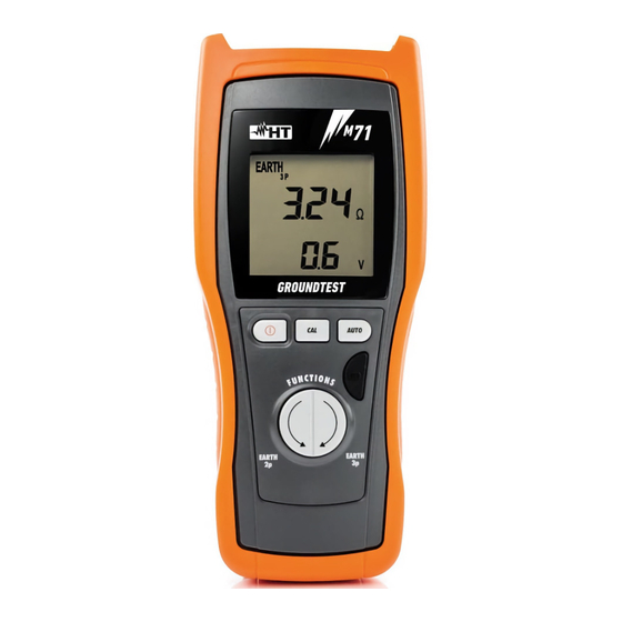
GroundTest M71 4. WORKING INSTRUCTIONS 4.1. INSTRUMENT DESCRIPTION CAPTION: 1. Inputs 2. Display 3. ON/OFF key 4. CAL key 5. Switch of test mode 6. AUTO key 7. GO key Fig. 1: Instrument's front panel 4.2. FUNCTION KEYS DESCRIPTION ON/OFF Key to switch on and off the instrument. -
Page 8: Switching On
GroundTest M71 4.2.1. Switching on When switching on the instrument a brief tone is audible along with display of all segments for about one second. Subsequently the last firmware version as well as the last selected measuring mode are displayed before switching off. -
Page 9: Earth 2W:two-Wire Earth Resistance Measurement
GroundTest M71 4.4. EARTH 2W:TWO-WIRE EARTH RESISTANCE MEASUREMENT 4.4.1. EARTH 2W- Zero setting of cables CAUTION The instrument can be used for voltage and current measurements on installations with overvoltage category equal to CAT III 240V to earth and maximum voltage of 415V between inputs. Do not connect the instrument to installations whose voltages exceed the limits indicated in this manual. - Page 10 GroundTest M71 After pressing the CAL key the instrument carries out zero setting of cables' resistance (this procedure takes approx. 30sec). Cables with a resistance up to 2can be calibrated. CAUTION When “Measuring…” is displayed the instrument is effecting measurement.
-
Page 11: Earth 2W- Measurement Procedure
GroundTest M71 4.4.2. EARTH 2W- Measurement procedure CAUTION The instrument can be used for voltage and current measurements on installations with overvoltage category equal to CAT III 240V to earth and maximum voltage of 415V between inputs. Do not connect the instrument to installations whose voltages exceed the limits indicated in this manual. - Page 12 GroundTest M71 CAUTION The instrument displays the sum value of R as result. Therefore the measurement achieved is: The closer to R (prospective value) the more negligible the value R of the auxiliary earth rod with respect to R itself ...
-
Page 13: Message Description For Earth 2W Measurement
GroundTest M71 4.4.3. Message description for EARTH 2W measurement 1. If the following condition is met: < 0.11 DISPLAYED the instrument displays the symbol Errore. Non si possono creare oggetti dalla modifica di codici di campo. indicating that the reading may be affected by relative error higher than 30%. -
Page 14: Earth 3W: Three Wire Earth Resistance Measurement
GroundTest M71 4.5. EARTH 3W: THREE WIRE EARTH RESISTANCE MEASUREMENT 4.5.1. EARTH 3W- Zero setting of cables CAUTION The instrument can be used for voltage and current measurements on installations with overvoltage category equal to CAT III 240V to earth and maximum voltage of 415V between inputs. - Page 15 GroundTest M71 CAUTION When “Measuring…” is displayed the instrument is effecting measurement. During this phase do not disconnect test leads from the instrument. 7. At the end of the test the measured value Symbol CAL: indicates that the is stored by the instrument and used as...
-
Page 16: Earth 3W- Measurement Procedure
GroundTest M71 4.5.2. EARTH 3W- Measurement procedure CAUTION The instrument can be used for voltage and current measurements on installations with overvoltage category equal to CAT III 240V to earth and maximum voltage of 415V between inputs. Do not connect the instrument to installations whose voltages exceed the limits indicated in this manual. - Page 17 GroundTest M71 Press the instrument's start key. Select function EARTH 3W pressing the right arrow key. If the circuit under test is assumed to be affected by electric noise press the AUTO key to select the corresponding mode. Connect the red cable and the green cable into the corresponding instrument's input terminals.
-
Page 18: Message Description For Earth 3W Measurement
GroundTest M71 4.5.3. Message description for EARTH 3W measurement 1. If the following condition is met: < 0.11 DISPLAYED the instrument displays the symbol Errore. Non si possono creare oggetti dalla modifica di codici di campo. indicating that the reading may be affected by a relative error higher than 30%. - Page 19 GroundTest M71 6. If the volt metric circuit (terminal S) shows a too high resistance value the side message is displayed. Check connection of red and green wires as well as their integrity. If the problem still exists connect two or...
-
Page 20: Maintenance
GroundTest M71 5. MAINTENANCE 5.1. GENERAL 1. This instrument is a precision meter. During its use and storage you are recommended to keep the instructions listed in this manual to avoid any harm or danger 2. Do not use the instrument in excessively wet environments and under high temperatures. -
Page 21: Technical Specifications
GroundTest M71 6. TECHNICAL SPECIFICATIONS 6.1. TECHNICAL FEATURES Accuracy is calculated as [% rdg + (dgt number) * resolution] at 23°C ± 5°C,< 80%HR CAUTION Under modes EARTH-2W and EARTH-3W the instrument displays the symbol of warning whenever: It is working under critical conditions, such as in the presence of input voltages ... -
Page 22: Safety Standards
GroundTest M71 6.1.1. Safety standards Instrument safety: IEC/EN61010-1, IEC/EN61557-1 EMC : IEC/EN61326-1 Technical literature: IEC/EN61187 Accessory safety: IEC/EN61010-031, IEC/EN61010-2-032 Insulation: double insulation Pollution degree: Maximum height: 2000m (6561ft) Measurement category: CAT III 240V to earth, maximum 415V between inputs Earth resistance : IEC/EN61557-5 6.1.2. -
Page 23: Service
GroundTest M71 7. SERVICE 7.1. WARRANTY TERMS This instrument is guaranteed against material and manufacturing defects, in compliance with our general sales terms. During the warranty period all defective parts may be replaced, but the manufacturer reserves the right to decide either to repair or replace the product. -
Page 24: Practical Reports For Electrical Tests
GroundTest M71 8. PRACTICAL REPORTS FOR ELECTRICAL TESTS 8.1. EARTH RESISTANCE MEASUREMENT IN TT SYSTEMS PURPOSE OF THE TEST Make sure that the RCD is coordinated with the earth resistance value. It is not possible to take an earth resistance value as reference limit when controlling the measurement result, while it is always necessary to check that the coordination complies with the standards' requirements. -
Page 25: Earth Resistance Measurement, Volt Ampere Metric Method
GroundTest M71 8.2. EARTH RESISTANCE MEASUREMENT, VOLT AMPERE METRIC METHOD Method for small sized earth rods Let current stream between the earth rod and a current probe placed at a distance equal to fivefold the diagonal of the area limiting the earth installation. Place the voltage probe at approximately half way between the earth rod and the current probe, finally measure voltage between both of them. - Page 26 GroundTest M71 Method for medium and large sized earth rods This procedure is based on the volt ampere metric method as well, however it is mainly used whenever it is difficult to place an auxiliary current rod at a distance equal to fivefold the diagonal of the area limiting the earth installation.
Need help?
Do you have a question about the GroundTest M71 and is the answer not in the manual?
Questions and answers