Satel VERSA Instructions For Use Manual
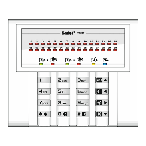
Operating control panel from led keypad
Hide thumbs
Also See for VERSA:
- Programming manual (87 pages) ,
- User manual (54 pages) ,
- Operating instructions manual (32 pages)

Related Manuals for Satel VERSA


Summary of Contents for Satel VERSA
- Page 1 INSTRUCTIONS FOR OPERATING CONTROL PANEL FROM LED KEYPAD SATEL sp. z o.o. ul. Budowlanych 66 80-298 Gdańsk POLAND tel. 58 320 94 00 www.satel.eu versa_led_en 09/15...
- Page 2 Changes, modifications or repairs not authorized by the manufacturer shall void your rights under the warranty. SATEL's goal is to continually upgrade the quality of its products, which may result in alterations of their technical specifications and firmware. The current information on the introduced modifications is available on our website.
-
Page 3: Table Of Contents
CONTENTS Introduction........................3 Keypad description ......................3 LEDs presenting partition and system state................4 LEDs presenting zone status ....................4 Keys ............................5 Sound signaling........................6 2.4.1 Beeps generated when operating ....................6 2.4.2 Beeps generated during programming..................6 2.4.3 Events signaled by sounds......................6 Operating the alarm system .................. - Page 4 VERSA SATEL 3.18.1 Quick control of outputs ......................26 3.18.2 Controlling the outputs by means of function ................26 3.19 Tests ............................ 26 3.19.1 Zone test ............................. 26 3.19.2 Output test ..........................27 3.19.3 Checking the level / quality of radio signal ................. 27 3.19.4...
-
Page 5: Introduction
The SATEL Company is manufacturer of a broad range of devices dedicated for use in security alarm systems. Further information is available on our website www.satel.eu or at the points of sale offering our products. -
Page 6: Leds Presenting Partition And System State
VERSA SATEL LEDs presenting partition and system state Color Description green indicates the partition state (each partition has its own LED) ON – partition is armed blinking – exit delay countdown is running in partition indicates alarm or alarm memory in the partition (each partition has its own LED) The way of presenting the information is shown graphically below. -
Page 7: Keys
SATEL VERSA 30 numbered LEDs provide information about the status of zones. The LED numbers correspond to the zone numbers. When the user functions are in use, the LEDs can present other information. The way of presenting information is shown graphically below. The information is presented for 2 seconds and repeated ( –... -
Page 8: Sound Signaling
VERSA SATEL Sound signaling The installer can disable the sound signaling. 2.4.1 Beeps generated when operating 1 short beep – pressing any number key. 3 short beeps – confirmation of: – starting the arming procedure (there is exit delay in the partition) or arming (there is no exit delay in the partition), –... -
Page 9: Operating The Alarm System
SATEL VERSA Continuous beep – alarm. Long beep every second – fire alarm. 3. Operating the alarm system Codes Operating the alarm system by means of the keypad is possible after entering the code. Only some functions can be run without the code being entered. -
Page 10: Arming The Selected Partition
VERSA SATEL 3.2.2 Arming the selected partition 1. Indicate the partition which is to be armed (press one of the keys: - partition 1; - partition 2). 2. Select the arming mode (press one of the keys: - full arming;... -
Page 11: Disarming And Alarm Clearing
SATEL VERSA Disarming and alarm clearing Disarming and alarm clearing are carried out in the same way, the procedures being interconnected. If the partition is armed and an alarm is triggered in it, then disarming will also mean alarm clearing. -
Page 12: Turning The Chime On /Off
VERSA SATEL medical (auxiliary) alarm – press for approx. 3 seconds, panic alarm – press for approx. 3 seconds. The installer defines whether the loud panic alarm (setting off the loud alarm signal) or the silent panic alarm (without the loud signal) will be triggered. - Page 13 SATEL VERSA see Table 1. LEDs 1-4 present the first character, LEDs 5-8 – the second, LEDs 9-12 – the third, LEDs 16-19 – the fourth, LEDs 20-23 – the fifth, and LEDs 24-27 – the sixth character. LED status Digits and characters –...
-
Page 14: User Functions List
VERSA SATEL 3.7.4 User functions list Shown in square brackets are key sequences that enable starting the given function. The functions that are only available after entering the service code have been specially highlighted (white text against black background). The access to other functions depends on the user rights. -
Page 15: Adding A User
SATEL VERSA 3.9.1 Adding a user 1. Enter the user menu and press in turn . Adding the user is effected by the step by step” method, hence the p “ rogramming step number is presented on the LEDs of the first and second partitions (see: page 11, Table 1). - Page 16 VERSA SATEL 6. Step 5a. Selecting 433 MHz keyfob addition method ress (if the keyfob serial number is to be entered) or press in turn (if the serial number is to be read by the device which su pports the keyfobs during transmiss 7.
- Page 17 SATEL VERSA 11. Zone 11 violation 12. Zone 12 violation 13. Zone 13 violation 14. Zone 14 violation 15. Zone 15 violation 16. Zone 16 violation 17. Zone 17 violation 18. Zone 18 violation 19. Zone 19 violation 20. Zone 20 violation 21.
- Page 18 VERSA SATEL 71. Output 1 deactivation 72. Output 2 deactivation 73. Output 3 deactivation 74. Output 4 deactivation 75. Output 5 deactivation 76. Output 6 deactivation 77. Output 7 deactivation 78. Output 8 deactivation 79. Output 9 deactivation 80. Output 10 deactivation 81.
- Page 19 SATEL VERSA – press twice any button on the keyfob Fig. 5. APT-100 keyfob (gray enclosure). A – numeration of LEDs. B – numeration of keyfob buttons (button 6 – pressing buttons 1 and 5 simultaneously). 17. Step 6c. Assigning function to APT-100 keyfob button 1. Proceed in the same way as in Step 5c.
-
Page 20: User Editing
VERSA SATEL 12. Output 12 state 13. Arming: Partition 1 LED is ON when partition 1 is armed 14. Arming: Partition 2 LED is ON when partition 2 is armed 15. Arming: Partition 1 or 2 LED is ON when partition 1 or 2 is armed 16. - Page 21 SATEL VERSA 2. Step 1. Selecting user whose data are to be edited. You can make your selection by using the keys or by entering the user number (the LED designated by number of se lecte d user should start blinking). Having selected the user, press You can press to interrupt the procedure of editing a user.
-
Page 22: Removing A User
VERSA SATEL – in turn, if you want to add a card (the procedure is much similar to that for adding a card to a new user), – , if you want to remove a card. 3.9.3 Removing a user 1. -
Page 23: Zone Isolating
SATEL VERSA LED OFF – the zone is to be unbypassed. Press to quit the function. The zones will be inhibited/unbypassed. 3.11. Zone isolating The isolated zone will remain bypassed until it is unbypassed by the user. Enter the user menu and press in turn . -
Page 24: Programming The Weekly Schedule
VERSA SATEL 3. Step 2. Selecting parameters to be programmed. Press in turn the suitable keys to select a parameter: - weekly schedule, - exception 1, - exception 2, - exception 3, - exception 4, - partition 1 arming mode, - partition 2 arming mode. -
Page 25: Selecting The Arming Mode
SATEL VERSA 3.14.3 Selecting the arming mode 1. Define whether and what arming mode is to be activated by the timer (press one of the keys: - full arming; - night arming; - day arming; - timer does not arm the partition). The LEDs indicate what selection you have made (LED 1 blinking – full arming;... -
Page 26: Programming Codes To Acknowledge / Clear Messaging
VERSA SATEL Specia char acter Function description switch-over to pulse dialing switch-over to tone dialing (DTMF) waiting for additional signal 3 second pause 10 second pause signal in DTMF mo e signal # in DTMF mode ther nals g era d in DTMF mode 4. -
Page 27: Trouble Handling Procedure
/ no co mmunication with device selected for mmunicati on test (PING) / n o connection to SATEL server / MAC/ID error, LED 12 - hort-circuit i n communication b LED 13 - ntrol pane... -
Page 28: Output Control
VERSA SATEL 3.18 O t ut control Using th keypad, you can control the opera tion of devices connected to the outputs (e.g. to raise/lower roller blinds/shutters, turn on/off lighting or heating, etc.) . The installer defines how the ou puts should work (whether the output will be activated for a defined time, or it will remain active until deactivated by the user, timer, etc.). -
Page 29: Output Test
the quality of radio signal received by the controller from 433 MHz wire s detectors (if the VERSA-MCU controller is con nected to the control panel), the level of radio signal received by the controller from ABAX wire s devices (if the ABAX system controller is connected to the control panel). -
Page 30: Service
VERSA SATEL deactivate for 16 seconds the 11. F function output (to clear IRE DETECTORS POWER SUPPLY the alarm memory of fire detectors), activate the 21. D function output. ECTORS RESETTING Enter the user menu a nd press in turn 3.20 Service...
Need help?
Do you have a question about the VERSA and is the answer not in the manual?
Questions and answers