Satel Versa User Manual
Alarm control panel
Hide thumbs
Also See for Versa:
- Programming manual (87 pages) ,
- User manual (54 pages) ,
- Operating instructions manual (32 pages)
Table of Contents
Advertisement
Quick Links
Advertisement
Table of Contents

Related Manuals for Satel Versa


Summary of Contents for Satel Versa
- Page 1 USER MANUAL GDAŃSK versa_u_en 03/09...
- Page 2 To ensure adequate protection, the alarm security system must be in good working order, therefore SATEL recommends that it be regularly tested. The alarm security system cannot prevent burglary, assault or fire from happening, but it...
-
Page 3: Table Of Contents
CONTENTS ........................2 NTRODUCTION ............2 ECHNICAL ERFORMANCE OF ECURITY LARM YSTEM ..................2 LARM YSTEM PERATING OSTS ....................... 3 ENERAL ESCRIPTION ........................3 PERATION 5.1 LED .......................... 4 FUNCTIONS 5.2 LCD ......................5 DISPLAY FUNCTIONS 5.3 S ................ 6 TATES SIGNALED ACOUSTICALLY ON THE KEYPAD 5.4 E .................. -
Page 4: Introduction
VERSA 1. Introduction We are happy you have chosen a product offered by SATEL and hope you will be satisfied with your choice. Please be assured that we are always ready to provide you with professional assistance and information on our products. -
Page 5: General Description
5. Operation This manual describes the operating rules for the VERSA control panel. Basic operation of the alarm system is limited to arming / disarming and suitably responding to the information which may be signaled by the control panel. -
Page 6: Led Functions
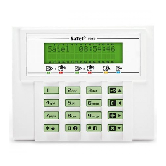
Operation mode of the backlight is specified by the installer. Fig. 2. View of the VERSA-LCD-GR keypad. 5.1 LED functions The LEDs provide information on the alarm system status and are designated by the following symbols: (red color) –... -
Page 7: Lcd Display Functions
VERSA SATEL (yellow color) – trouble indicator. TROUBLE • Blinking slowly – indicates that a trouble has occurred in the alarm system. The LED goes off on arming one or two partitions, on clearing the cause of trouble or after executing the current trouble check function (user function no. 7) and clearing the trouble memory. -
Page 8: States Signaled Acoustically On The Keypad
User Manual VERSA LED blinking mask – OFF, – ON Description zone bypassed *) long violation trouble *) no violation trouble *) memory of first violation in armed mode (the zone triggered alarm in the partition or was violated as first, but is no longer violated), the... -
Page 9: Events Signaled On Alarm Outputs
VERSA SATEL • two short beeps every 2.5 sec – signaling a new trouble; • five short beeps – violation of a zone with "CHIME" option; • a series of beeps with diminishing duration every 5 sec – auto-arming delay countdown. -
Page 10: Signaling Warning Alarm
User Manual VERSA reported tamper is not cleared, the trouble signaling will continue and the message will not disappear. If the S option is not enabled by the installer, only the ERVICE MESSAGE AFTER TAMPER ALARM ] LED will be blinking after the tamper alarm is cleared, and the date and time TROUBLE will be displayed on the LCD keypad. -
Page 11: Armed Mode Of The Control Panel
If the code is to control both partitions, it can be used to arm/disarm the selected partition or both partitions simultaneously. In order to adjust the alarm system to various situations, the VERSA control panel offers a few partition armed modes. -
Page 12: Day Armed Mode (3)
User Manual VERSA 5.8.3 Day armed mode (3) Supervision mode during which some detectors indicated by the installer are inactive (e.g. those monitoring the interior of the whole apartment). Violation of the active detectors results in normal reaction of the control panel, as in the full armed mode. Usually, the area within which movement is possible inside the protected premises (partition) with activated day armed mode is larger than with activated night armed mode. -
Page 13: Code Arming
Example: Arm the second partition by the "VERSA" code in the night armed mode. The code controls both partitions. Press in turn: In order to change the armed mode, if it is already activated, proceed exactly in the same way as during the ordinary arming. -
Page 14: Quick Arming
(provided they are active). In order to disarm just one partition using such a code, entering the code must be preceded by pressing in turn the key with partition number and the disarming key. Example: Disarm both partitions with "VERSA" code controlling both partitions. Press in turn:... -
Page 15: Controlling The Control Panel Armed Mode With Proximity Cards
VERSA SATEL Example : Disarm partition II only with "VERSA" code controlling both partitions. Press in turn: If you make a mistake when entering the code, press the key and reenter the code. The control panel will confirm acceptance of the command by four short beeps and one long... -
Page 16: Auto-Arming Deferment
User Manual VERSA way round. The timer can control one or two partitions. The installer will set the so-called T IMER option for each partition. If the option is enabled, disarming will be always done by the PRIORITY timer. If the option is disabled, partition will only be disarmed by the timer, if it was armed by the timer. -
Page 17: Panic Alarm
VERSA SATEL The function may be disabled by the installer. 6.5 Panic alarm The function enables panic alarm to be triggered from the keypad. The control panel initiates signaling on the alarm output, in the keypad and sends the appropriate code to the monitoring station. - Page 18 User Manual VERSA pressed, the LCD keypad will display the submenu name for two seconds, and then will open the list of functions available in the submenu. Also the LED keypad will wait 2 seconds and then it will enter the submenu.
- Page 19 VERSA SATEL Calling up the menu: CODE Name in LCD keypad Description Main menu Submenu Service Service related functions Service mode Entering the service mode *) Starting telephone connection between the control panel Start DwnlTEL and the service computer – the control panel will call the...
- Page 20 Manual start of the test transmission MS1 test Test of reporting to station 1 MS2 test Test of reporting to station 2 VERSA version Reading the version of control panel program Expander ver. Reading the version of connected module program Supply volt.
-
Page 21: Entering Changes To The User Functions
VERSA SATEL 8.1 Entering changes to the user functions 8.1.1 Options Depending on the function, the control panel will make available for modification a single option or a set of options (so-called multiple choice list). In the LCD keypad, the option status is indicated by means of a special character in the right... - Page 22 User Manual VERSA The H consist of digits 0-9 and characters A-F (see: Table 5). To enter EXADECIMAL NUMBERS the digits 0-9, use the keys in the same way as for the decimal numbers, while to enter the characters A-F, use the key, pressing it (2, 3 or 4 times) until the required character is displayed.
-
Page 23: Telephone Numbers
VERSA SATEL Fig. 3. Examples of presenting decimal values by means of LEDs in VERSA-LED-GR keypad. In both examples, 3-digit values are programmed. Value 30 (030) has been programmed in example A, value 160 - in example B. 8.1.3 Telephone numbers The tone dialed T may contain special characters. -
Page 24: Names
[ABC] mode. Press the key to change the mode from [ABC] to [abc] and vice versa, however this type of keypad does not show in which mode it currently is. It does not show characters entered in the lower case mode [abc] either. -
Page 25: Detailed Description Of The User Functions
RS-232 TTL port. The DB9FC/RJ-KPL designated cable is manufactured by SATEL and should be available from the hardware distributor. The function is available to the service. - Page 26 User Manual VERSA The LCD keypad displays all the entered digits and enables code editing. The LED keypad displays up to 6 digits of the code and offers no editing capability. If the new code consists of more digits, the 7 and 8 digit will not be visible.
- Page 27 VERSA SATEL Users editing Control Programming DOWNLOAD/SERVICE Inspection Tests DURESS Key fob button functions (see: Table 12) Button 1 Button 2 Button 3 Button 4 Buttons 1 and 2 Buttons 1 and 3 Table 9. Privilege assignment to particular user schedules and key fob key functions (factory default settings).
- Page 28 User Manual VERSA If the number is entered manually, you should only press the confirmation key, enter the key fob number serial (which can be found on the packing) and confirm it again. The keypad will proceed to the stage of assigning the control...
- Page 29 VERSA SATEL Output 2 Activating output 2 … … … Output 12 Activating output 12 Output 1 Deactivating output 1 Output 2 Deactivating output 2 … … … Output 12 Deactivating output 12 Toggling output 1 (changing output Output 1...
- Page 30 User Manual VERSA blinking means entering the number manually. The selection should be confirmed. h) To read in the card by means of the reader, present the card briefly (for 0.5 s) to the reader face for the first time and then remove it.
- Page 31 VERSA SATEL b) An extra feature when editing the card is the option to remove the card which was previously assigned to the user. The following operations can be carried out Key number Selection meaning LED indication LED no. 1 blinking...
- Page 32 User Manual VERSA EVENT LOG Calling up this function will enable (re)viewing the event log. The function is only available from the LCD keypad. The events are sorted chronologically by date and time of their occurrence. Using arrow keys you can go to the previous/next event saved in the control panel memory.
- Page 33 VERSA SATEL – LED OFF; – LED ON. Programming stage Select timer for editing What is to be changed? Change parameter settings Table 17. Indication of successive stages of programming the on the keypad by means of LEDs. IMER SETTINGS Having called up the function, press the key with timer number (from 1 to 4) and confirm the selection.
- Page 34 User Manual VERSA Programming stage Monday Tuesday Wednesday Thursday Friday Saturday Sunday Daily Table 19. Indication of successive stages of programming TIMER on the keypad by means of ACTIVATIONS DEACTIVATIONS LEDs. Exception Programming stage Begin exception (date) End exception (date) Exception arm/disarm Table 20.
- Page 35 VERSA SATEL items). Using the numerical keys or arrow keys, select the telephone number to be changed and press . Then, enter the new telephone number and confirm the change. If the number requires entering special characters, program them according to the description on page 22.
- Page 36 User Manual VERSA Zones – no violation Zones – masking Wireless device battery low Wireless device communication loss Module tamper No presence (module) AC loss (module) Battery trouble (module) Power output overload (module) Low battery (key fobs) Module restart Control panel restart HSE (processor) system trouble Table 22.
- Page 37 If the progress of monitoring is correct, it will be ended by displaying the "Event sent" message. 9 7 # VERSA version The function makes it possible to check the type designation and firmware version (number and build date) of the control panel.
-
Page 38: Using Proximity Cards For System Control
User Manual VERSA firmware version (number and build date). The arrow keys enable the user to scroll through the list of modules identified in the system. Available from the LCD keypad only. 9 9 # Supply volt. The function makes it possible to check the supply voltage for the connected modules. -
Page 39: Using Remote Control Key Fob In The System
(key fobs), working at 433MHz frequency, which are manufactured by SATEL. The four-button key fob enables 6 different functions to be executed (keys 1, 2, 3, 4 and key combinations: 1 and 2, 1 and 3). Similarly, the two-button key fob allows the user to execute 3 different functions (keys 1, 2 and combination 1 and 2). -
Page 40: Short Description Of Keypads
User Manual VERSA 11. Short Description of Keypads trouble – signaling armed (supervision) alarm detection of a technical lit – partition armed lit – alarm in partition problem in the system – blinking – exit delay countdown blinking – alarm memory check by means of user function no. - Page 41 95# – Test monitoring station no. 1 LED 17 ON – night armed mode 96# – Test monitoring station no. 2 LED 18 ON – day armed mode 97# – VERSA version LED 16,17,18 OFF – disarmed 98# – Expander versions 99# – Supply voltage 90# –...
- Page 42 SATEL sp. z o.o. ul. Schuberta 79 80-172 Gdańsk POLAND tel. + 48 58 320 94 00 info@satel.pl www.satel.pl...
Need help?
Do you have a question about the Versa and is the answer not in the manual?
Questions and answers