
Subscribe to Our Youtube Channel
Related Manuals for Atlas Copco HB Series


Summary of Contents for Atlas Copco HB Series
- Page 1 5800, 5800 DP, 7000, 7000 DP, 10000 DP Safety and operating instructions Hydraulic breakers © 2012 Atlas Copco Construction Tools GmbH | No. 3390 5005 01 | 2012-05-03 Original instructions...
-
Page 3: Table Of Contents
Mechanical disassembly ............27 © 2012 Atlas Copco Construction Tools GmbH | No. 3390 5005 01 | 2012-05-03... - Page 4 Filling/topping up the piston accumulator ........52 © 2012 Atlas Copco Construction Tools GmbH | No. 3390 5005 01 | 2012-05-03...
- Page 5 EC Declaration of Conformity (EC Directive 2006/42/EC) ......69 © 2012 Atlas Copco Construction Tools GmbH | No. 3390 5005 01 | 2012-05-03...
-
Page 7: Introduction
Action step in a safety instruction ► Action step ♦ Established operation process Explanation of the elements of a drawing ● Listing ● ● © 2012 Atlas Copco Construction Tools GmbH | No. 3390 5005 01 | 2012-05-03 Original instructions... - Page 8 INTRODUCTION HB 5800, 5800 DP, 7000, 7000 DP, 10000 DP Symbols used in illustrations have the following meanings: permitted operation prohibited operation © 2012 Atlas Copco Construction Tools GmbH | No. 3390 5005 01 | 2012-05-03 Original instructions...
-
Page 9: Safety Instructions
Read the carrier manufacturer's Safety and operating Instructions before attaching the hydraulic attachment to the carrier and operating it. Observe all instructions. © 2012 Atlas Copco Construction Tools GmbH | No. 3390 5005 01 | 2012-05-03 Original instructions... -
Page 10: Qualification
● safety glasses with side protectors ● ● protective gloves protective shoes ● warning vest ● ● hearing protection © 2012 Atlas Copco Construction Tools GmbH | No. 3390 5005 01 | 2012-05-03 Original instructions... -
Page 11: Transport, Precautions
Only fill the piston accumulator with nitrogen (N ► © 2012 Atlas Copco Construction Tools GmbH | No. 3390 5005 01 | 2012-05-03 Original instructions... -
Page 12: Media/Consumables, Precautions
Make sure that there are no hidden circuits in the contaminated by oil or grease with water and soap. work area. ► Check wiring diagrams. © 2012 Atlas Copco Construction Tools GmbH | No. 3390 5005 01 | 2012-05-03 Original instructions... -
Page 13: Falling Stones, Precautions
Only use original parts or accessories approved ► by Atlas Copco. ► Modifications that entail new hazards may require a new procedure for assessing conformity. © 2012 Atlas Copco Construction Tools GmbH | No. 3390 5005 01 | 2012-05-03 Original instructions... -
Page 14: Environmental Pollution, Precautions
► Contact an authorized waste management company. Dispose of all contaminated material in accordance ► with the applicable environmental regulations. © 2012 Atlas Copco Construction Tools GmbH | No. 3390 5005 01 | 2012-05-03 Original instructions... -
Page 15: Overview
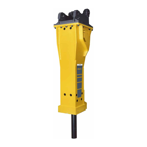
OVERVIEW Equipment description The picture gives an overview of the main parts and components of the hydraulic attachment. Actual details may differ. HB 5800/DP © 2012 Atlas Copco Construction Tools GmbH | No. 3390 5005 01 | 2012-05-03 Original instructions... -
Page 16: Function
Working tool aperture protective cap The working tool can be replaced as required. The working tool is not included in the scope of supply of the hydraulic breaker. © 2012 Atlas Copco Construction Tools GmbH | No. 3390 5005 01 | 2012-05-03 Original instructions... -
Page 17: Signs / Labels
Model Part number Max. permissible operating pressure Year of manufacture of product group Name and address of manufacturer Serial number Weight of product group © 2012 Atlas Copco Construction Tools GmbH | No. 3390 5005 01 | 2012-05-03 Original instructions... -
Page 18: Labels
Changes not carried out by or in consultation with Instructions must be read prior the manufacturer to use of the hydraulic attachment and in particular the chapter on Safety. © 2012 Atlas Copco Construction Tools GmbH | No. 3390 5005 01 | 2012-05-03 Original instructions... -
Page 19: Removing The Packaging
Allen screws and pairs of lock washers e.g. hydraulic fittings for the carrier ● ● e.g. piston retainer e.g. calliper upper wear bush ● © 2012 Atlas Copco Construction Tools GmbH | No. 3390 5005 01 | 2012-05-03 Original instructions... -
Page 20: Transport
● seam. Contact the Atlas Copco Customer Center/Dealer ► in your area if the lifting eye is worn in any way. © 2012 Atlas Copco Construction Tools GmbH | No. 3390 5005 01 | 2012-05-03 Original instructions... -
Page 21: Transport Using A Forklift Truck
♦ Slowly lift the hydraulic attachment. ♦ Transport the hydraulic attachment to its intended destination. ♦ Place the hydraulic attachment on timber support blocks. © 2012 Atlas Copco Construction Tools GmbH | No. 3390 5005 01 | 2012-05-03 Original instructions... -
Page 22: Installation
An oil filter must be integrated in the tank line of the hydraulic system. The maximum mesh width allowed for the oil filter is 50 microns; it must have a magnetic separator. © 2012 Atlas Copco Construction Tools GmbH | No. 3390 5005 01 | 2012-05-03 Original instructions... -
Page 23: Manufacturing The Adapter Plate
Apply Anti-Seize to the Allen screw threads (A) before inserting them. The contact faces of the screw head and the lock washers (B) must not be lubricated. © 2012 Atlas Copco Construction Tools GmbH | No. 3390 5005 01 | 2012-05-03 Original instructions... -
Page 24: Attaching The Hydraulic Attachment To The Carrier
Consult the Atlas Copco Customer Center/Dealer in your area if the adapter plate is stopped by a mechanical stop. © 2012 Atlas Copco Construction Tools GmbH | No. 3390 5005 01 | 2012-05-03 Original instructions... -
Page 25: Making The Hydraulic Connections
► Immediately replace a defective swivel joint cover. ♦ Remove the caps from the ports »P« and »T« and save them for future use. © 2012 Atlas Copco Construction Tools GmbH | No. 3390 5005 01 | 2012-05-03 Original instructions... - Page 26 A hydraulic hose flailing about may cause serious injuries. ► Tighten the hydraulic hose connection nuts with the required tightening torque. Tightening torque (see chapter Bolt connections / Tightening torques) © 2012 Atlas Copco Construction Tools GmbH | No. 3390 5005 01 | 2012-05-03 Original instructions...
-
Page 27: Removing The Hydraulic Attachment From The Carrier
Only move the boom very slowly and in a controlled manner while an assistant is within the danger zone. Always keep sight of your assistant. ► © 2012 Atlas Copco Construction Tools GmbH | No. 3390 5005 01 | 2012-05-03 Original instructions... -
Page 28: Dustprotector
Remove the guide ring (F), floating ring (E) and ♦ counter ring (D) of the DustProtector system. Remove the wiper (A). ♦ To make the wiper (A) easier to remove: © 2012 Atlas Copco Construction Tools GmbH | No. 3390 5005 01 | 2012-05-03 Original instructions... -
Page 29: Working Tool
Do not reach into the aperture in the lower breaker ► No torsion effect part or between the working tool and the lower breaker part. © 2012 Atlas Copco Construction Tools GmbH | No. 3390 5005 01 | 2012-05-03 Original instructions... -
Page 30: Installation
When installing the working tool for the first time after it has been delivered, you must remove the protective cap and the retainer bars. © 2012 Atlas Copco Construction Tools GmbH | No. 3390 5005 01 | 2012-05-03 Original instructions... -
Page 31: Removal
Pull the working tool (G) out of the lower breaker part. ♦ If the hydraulic breaker is a DustProtector type, remove the wiper (F) (see chapter DustProtector/Removal). © 2012 Atlas Copco Construction Tools GmbH | No. 3390 5005 01 | 2012-05-03 Original instructions... -
Page 32: Operation
0 °C and +80 °C when operating the relief valve. breaker. The full capacity of the hydraulic attachment can be achieved when the oil temperature is approx. 60 °C. © 2012 Atlas Copco Construction Tools GmbH | No. 3390 5005 01 | 2012-05-03 Original instructions... -
Page 33: Switching The Hydraulic Breaker On And Off
♦ Depressurise the hydraulic system (see chapter Depressurising the hydraulic system). © 2012 Atlas Copco Construction Tools GmbH | No. 3390 5005 01 | 2012-05-03 Original instructions... -
Page 34: Advance
Start the hydraulic attachment when the temperature has risen to 0 °C. ♦ During operations, leave the carrier engine and pumps running even during breaks. © 2012 Atlas Copco Construction Tools GmbH | No. 3390 5005 01 | 2012-05-03 Original instructions... -
Page 35: Prohibited Operation
This will damage the hydraulic breaker, the working tool and the carrier. © 2012 Atlas Copco Construction Tools GmbH | No. 3390 5005 01 | 2012-05-03 Original instructions... -
Page 36: Blank Firing Of The Working Tool
♦ Reposition the carrier so that you do not have to work with the cylinder in its end positions. © 2012 Atlas Copco Construction Tools GmbH | No. 3390 5005 01 | 2012-05-03 Original instructions... -
Page 37: Working With Safety Equipment
♦ Before using the hydraulic in a hot environment, consult the Atlas Copco Customer Center/Dealer in your area. © 2012 Atlas Copco Construction Tools GmbH | No. 3390 5005 01 | 2012-05-03 Original instructions... -
Page 38: Startselect System Autostart/Autostop
Sudden movements of the carrier may cause serious injury. Secure the carrier such that it cannot move ► unexpectedly. Observe the carrier manufacturer’s instructions. ► © 2012 Atlas Copco Construction Tools GmbH | No. 3390 5005 01 | 2012-05-03 Original instructions... - Page 39 Screw in the plug (C) and tighten it to the required ♦ tightening torque (see chapter Bolt connections / Tightening torques). Install the plug (B) in the breaker box. ♦ © 2012 Atlas Copco Construction Tools GmbH | No. 3390 5005 01 | 2012-05-03 Original instructions...
-
Page 40: Poweradapt
Hydraulic adjustment of the carrier to enable working with the hydraulic breaker is still necessary, in spite of using PowerAdapt. PowerAdapt is not a pressure-relief valve. © 2012 Atlas Copco Construction Tools GmbH | No. 3390 5005 01 | 2012-05-03 Original instructions... -
Page 41: Maintenance
► Follow the instructions in the Operating Instructions of the carrier to prevent the hydraulic attachment starting by accident. © 2012 Atlas Copco Construction Tools GmbH | No. 3390 5005 01 | 2012-05-03 Original instructions... -
Page 42: Maintenance Schedule
Check the pressure in the piston accumulator. In case of dusty conditions: Clean and grease the DustProtector system. Check the adapter plate bolts for wear. © 2012 Atlas Copco Construction Tools GmbH | No. 3390 5005 01 | 2012-05-03 Original instructions... -
Page 43: Depressurising The Hydraulic System
Case 2: © 2012 Atlas Copco Construction Tools GmbH | No. 3390 5005 01 | 2012-05-03 Original instructions... -
Page 44: Cleaning
II automatic lubrication system has been installed, a lubrication pulse is triggered whenever the hydraulic breaker is switched on. Adjust the lubricant supply to your work method. ♦ © 2012 Atlas Copco Construction Tools GmbH | No. 3390 5005 01 | 2012-05-03 Original instructions... -
Page 45: Automatic Lubrication
ContiLube II operation once a week. Emergency lubrication is possible via the grease ® nipple (B) on the rear of the ContiLube © 2012 Atlas Copco Construction Tools GmbH | No. 3390 5005 01 | 2012-05-03 Original instructions... -
Page 46: Manual Lubrication
Hydraulic breaker without DustProtector: 5 to 15 strokes from the manual grease gun ● Hydraulic breaker with DustProtector: 5 to 10 strokes from the manual grease gun © 2012 Atlas Copco Construction Tools GmbH | No. 3390 5005 01 | 2012-05-03 Original instructions... -
Page 47: Checking The Tensioning Bolts
(B and C). ♦ Check the wear condition of the impact ring if you detect deformations (B). Replace impact ring if necessary. © 2012 Atlas Copco Construction Tools GmbH | No. 3390 5005 01 | 2012-05-03 Original instructions... -
Page 48: Checking The Retainer Bars
The plugs must not be damaged. your area. Remove all remnants of lubricant from the inside ♦ of the lower breaker part before installing new parts. © 2012 Atlas Copco Construction Tools GmbH | No. 3390 5005 01 | 2012-05-03 Original instructions... -
Page 49: Checking And Cleaning The Dustprotector System
The inspection frequency depends on how much dust is generated: Normal dust generation: once a week (assuming 40–50 hours of operation). © 2012 Atlas Copco Construction Tools GmbH | No. 3390 5005 01 | 2012-05-03 Original instructions... -
Page 50: Piston Accumulator
Clean and grease the floating ring (E), counter ♦ ring (D) and guide ring (F) and install them again HB 7000, HB 7000 DP (see chapter DustProtector/Installation). © 2012 Atlas Copco Construction Tools GmbH | No. 3390 5005 01 | 2012-05-03 Original instructions... -
Page 51: Checking The Pressure In The Piston Accumulator
9.4 bar 12.5 bar HB 5800 DP HB 7000, 9.0 bar 11.5 bar HB 7000 DP HB 10000, 9.0 bar 11.1 bar HB 10000 DP © 2012 Atlas Copco Construction Tools GmbH | No. 3390 5005 01 | 2012-05-03 Original instructions... -
Page 52: Release The Pressure From The Piston Accumulator
Close the pressure relief valve (D). ♦ Connect the filling hose end (H) to the minimess ♦ connection (C) of the pressure relief valve (D). © 2012 Atlas Copco Construction Tools GmbH | No. 3390 5005 01 | 2012-05-03 Original instructions... -
Page 53: Hp-Accumulator
If no change in pressure is found at that stage, then testing can be switched to annual. © 2012 Atlas Copco Construction Tools GmbH | No. 3390 5005 01 | 2012-05-03 Original instructions... -
Page 54: Checking The Adapter Plate And The Breaker Box For Cracks And/Or Wear
♦ Check the adapter plate bolts for excessive wear such as cracks, pitting or severe erosion. ♦ Rework or replace worn bolts. © 2012 Atlas Copco Construction Tools GmbH | No. 3390 5005 01 | 2012-05-03 Original instructions... -
Page 55: Bolt Connections/Tightening Torques
Adapter plate under weekly Allen key 20 mm the HP- accumulator**** (Allen screws) Hose connections weekly Various open-ended spanners with different spanner sizes ® ContiLube © 2012 Atlas Copco Construction Tools GmbH | No. 3390 5005 01 | 2012-05-03 Original instructions... - Page 56 3. Place on the adapter plate, and tighten the fixing screws by hand in a crosswise fashion. 4. Tighten the fixing screws to 600 Nm, proceeding in a crosswise fashion © 2012 Atlas Copco Construction Tools GmbH | No. 3390 5005 01 | 2012-05-03 Original instructions...
- Page 57 HB 5800, 5800 DP, 7000, 7000 DP, 10000 DP MAINTENANCE HB 5800/DP HB 7000/DP © 2012 Atlas Copco Construction Tools GmbH | No. 3390 5005 01 | 2012-05-03 Original instructions...
- Page 58 MAINTENANCE HB 5800, 5800 DP, 7000, 7000 DP, 10000 DP HB 10000/DP © 2012 Atlas Copco Construction Tools GmbH | No. 3390 5005 01 | 2012-05-03 Original instructions...
-
Page 59: Troubleshooting
Adjust settings and replace defective parts if required your area PowerAdapt active Check the engine speed and/or mode stage of the carrier Carrier driver and lower as required (see chapter PowerAdapt) © 2012 Atlas Copco Construction Tools GmbH | No. 3390 5005 01 | 2012-05-03 Original instructions... -
Page 60: Hydraulic Breaker Operates Too Slowly
No gas in piston accumulator Check the gas pressure and fill the piston accumulator Carrier driver (see chapter Filling/topping up the piston accumulator) O-rings defective Replace O-rings Workshop © 2012 Atlas Copco Construction Tools GmbH | No. 3390 5005 01 | 2012-05-03 Original instructions... -
Page 61: Oil Leaks From Ports »P« Und »T
Oil or grease escapes from the ContiLube Cause Remedy Connecting fittings are loose Check the connecting fittings and tighten Workshop (see chapter Bolt connections/Tightening torques) © 2012 Atlas Copco Construction Tools GmbH | No. 3390 5005 01 | 2012-05-03 Original instructions... -
Page 62: Operating Temperature Too High
Pressure relief valve defective or valve with Fit new type-tested pressure relief cartridges or a more Workshop poor characteristic precise pressure-limiting valve © 2012 Atlas Copco Construction Tools GmbH | No. 3390 5005 01 | 2012-05-03 Original instructions... -
Page 63: Repair
Only use one type of hydraulic oil. ► ♦ Always specify which hydraulic oil has been used when sending in the hydraulic attachment to have it repaired. © 2012 Atlas Copco Construction Tools GmbH | No. 3390 5005 01 | 2012-05-03 Original instructions... -
Page 64: Storage
Contact the Atlas Copco Customer Center/Dealer ♦ in your area. Professionals trained by Atlas Copco Construction ♦ tools will disassemble the hydraulic breaker properly and: © 2012 Atlas Copco Construction Tools GmbH | No. 3390 5005 01 | 2012-05-03 Original instructions... -
Page 65: Working Tool
Do not expose the grease cartridges to direct ► sunlight. ♦ Store the grease cartridges in a cool, properly ventilated room. © 2012 Atlas Copco Construction Tools GmbH | No. 3390 5005 01 | 2012-05-03 Original instructions... -
Page 66: Disposal
Hydraulic oil ♦ Collect any hydraulic oil which escapes. Dispose of it in accordance with the applicable ♦ environmental regulations. © 2012 Atlas Copco Construction Tools GmbH | No. 3390 5005 01 | 2012-05-03 Original instructions... -
Page 67: Technical Specifications
3363 0904 83 3363 1003 91 Weights apply to standard carriers only. Any variances must be agreed with Atlas Copco and/or the carrier manufacturer prior to attachment Hydraulic breaker incl. breaker box, working tool and adapter plate of medium size. - Page 68 We, Atlas Copco, cannot be held liable for the consequences of using the declared values, instead of values reflecting the actual exposure, in an individual risk assessment in a work place situation over which we have no control.
-
Page 69: Ec Declaration Of Conformity (Ec Directive 2006/42/Ec)
2006/42/EC) EC Declaration of Conformity (EC Directive 2006/42/EC) We, Atlas Copco Construction Tools GmbH, hereby declare that the machines listed below conform to the provisions of EC Directive 2006/42/EC (Machinery Directive) and 2000/14/EC, ANNEX V (Noise Directive) and 97/23/EC (Pressure Equipment Directive), and the harmonised standards mentioned below. - Page 72 Any unauthorized use or copying of the contents or any part thereof is prohibited. This applies in particular to trademarks, model denominations, part numbers, and drawings. www.atlascopco.com...
Need help?
Do you have a question about the HB Series and is the answer not in the manual?
Questions and answers