Table of Contents
Advertisement
Quick Links
Instructions manual
Instructions manual
4812156501.pdf
4812156501.pdf
Operating & Maintenance
Operating & Maintenance
Rubber wheel roller
Rubber wheel roller
Diesel engine
Diesel engine
Cummins QSB 4.5 (IIIA/T3)
Cummins QSB 4.5 (IIIA/T3)
Cummins QSB 4.5 (IIIB/T4)
Cummins QSB 4.5 (IIIB/T4)
Serial number
Serial number
10000502x0B001380-
10000502x0B001380-
10000507x0B002258-
10000507x0B002258-
Translation of original instructions.
Translation of original instructions.
Reservation for changes
Reservation for changes
Printed in Sweden
Printed in Sweden
CP274
CP274
Advertisement
Table of Contents

Subscribe to Our Youtube Channel
Related Manuals for Atlas Copco Dynapac CP274


Summary of Contents for Atlas Copco Dynapac CP274
- Page 1 Instructions manual Instructions manual 4812156501.pdf 4812156501.pdf Operating & Maintenance Operating & Maintenance Rubber wheel roller Rubber wheel roller CP274 CP274 Diesel engine Diesel engine Cummins QSB 4.5 (IIIA/T3) Cummins QSB 4.5 (IIIA/T3) Cummins QSB 4.5 (IIIB/T4) Cummins QSB 4.5 (IIIB/T4) Serial number Serial number 10000502x0B001380-...
-
Page 3: Table Of Contents
Table of Contents Introduction ..........................1 The machine ....................1 Intended use ....................1 Warning symbols..................1 Safety information ..................1 General ....................... 2 CE marking and Declaration of conformity..........3 Safety - General instructions....................5 Safety - when operating ......................7 Slopes ...................... - Page 4 Technical specifications - Dimensions ................... 17 Dimensions ....................17 Weights and volumes................18 Working capacity..................19 General ..................... 19 Tightening torque ..................20 Wheel bolts ....................21 Hydraulic system..................21 Automatic Climate Control (ACC) (Optional)..........21 Machine description ....................... 23 Diesel engine ....................
- Page 5 Machine alarm................... 38 H1-AC alarm ..................... 39 LIMITED mode................39 SAFE mode ................39 "MAIN MENU" ................... 40 "USER SETTINGS" ..............41 Operator help when starting..............42 Operator help Workmode................42 ........................42 Instruments and controls, cab ..............43 Function description of instruments and controls in the cab ..... 44 Using the cab controls................
- Page 6 Starting ........................56 Starting the engine ..................56 Parking brake - Check................56 Throttle control and brake pedal............... 57 Display when activating choice via the button set........58 Alarm descriptions..................58 Operating the roller ................... 59 Operating on a slope................. 60 Checking the treads on the tires ...............
- Page 7 Hydraulic reservoir ..................69 Tires ......................70 Steering cylinder, hinges, etc..............70 Hoods, tarpaulin ..................70 Miscellaneous ........................71 Lifting ........................71 Lifting the roller..................71 Lifting the roller with jack:................71 Roller prepared for transport ..............72 Towing/Recovering....................72 Short distance towing with the engine running..........
- Page 8 Service - Checklist....................89 Maintenance, 10h ........................91 Diesel engine - Check oil level ..............91 Coolant level - Check ................92 Brake fluid level - Check ................92 Fuel tank - Refueling ................. 93 Hydraulic reservoir - Check fluid level............93 Water tank, Std - Filling................
- Page 9 Hydraulic fluid cooler Checking - Cleaning................105 Air conditioning (Optional) - Inspection....................106 Battery - Check condition ..................106 Edge cutter (Optional) - Lubrication .................... 107 Upper/Lower Pivot bearing - Lubrication..........107 Maintenance - 500 / 1500h ....................109 Hydraulic fluid cooler Checking - Cleaning................
- Page 10 Air conditioning (Optional) - Inspection....................120 Battery - Check condition ..................120 Edge cutter (Optional) - Lubrication .................... 121 Diesel engine Oil change ....................121 Engine Replacing oil filter..................122 The engine fuel filter - replacement/cleaning .......... 123 Hydraulic reservoir cap - Check .............. 124 Seat bearing - Lubrication ...............
- Page 11 Battery - Check condition ..................132 Edge cutter (Optional) - Lubrication .................... 133 Diesel engine Oil change ....................133 Engine Replacing oil filter..................134 The engine fuel filter - replacement/cleaning .......... 135 Hydraulic reservoir cap - Check .............. 136 Seat bearing - Lubrication ............... 136 Air cleaner Checking - Change the main air filter............
- Page 12 Air conditioning (Optional) Drying filter - Inspection ................145 Engine Replacing the coolant................145 Pivot bearing - Lubrication ..............146 Upper/Lower Pivot bearing - Lubrication..........146 4812156501.pdf 2012-12-14...
-
Page 13: Introduction
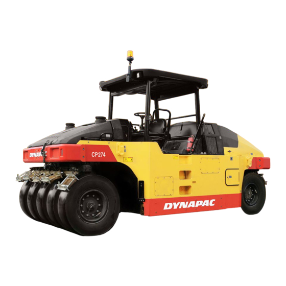
Introduction Introduction The machine Dynapac CP274 is a heavy rubber wheel roller in the 27 tonnes class, with a working width of 2300 mm. It has five guide wheels at the front, and four drive wheels at the back. The hydrostatic drives, flexible... -
Page 14: General
Introduction Read the entire manual before starting the Read the entire manual before starting the machine and before carrying out any machine and before carrying out any maintenance. maintenance. Replace immediately the instruction manuals if Replace immediately the instruction manuals if lost, damaged or unreadable. -
Page 15: Ce Marking And Declaration Of Conformity
Introduction THINK ENVIRONMENT ! Do not release oil, THINK ENVIRONMENT ! Do not release oil, fuel and other environmentally hazardous fuel and other environmentally hazardous substances into the environment. Always send substances into the environment. Always send used filters, drain oil and fuel remnants to used filters, drain oil and fuel remnants to environmentally correct disposal. - Page 16 Introduction 4812156501.pdf 2012-12-14...
-
Page 17: Safety - General Instructions
Safety - General instructions Safety - General instructions (Also read the safety manual) The operator must be familiar with the contents of the OPERATION section The operator must be familiar with the contents of the OPERATION section before starting the roller. before starting the roller. - Page 18 Safety - General instructions 17. Do not make any changes or modifications to the roller that could affect 17. Do not make any changes or modifications to the roller that could affect safety. Changes are only to be made after written approval has been given safety.
-
Page 19: Safety - When Operating
Safety - when operating Safety - when operating Prevent persons from entering or remaining in Prevent persons from entering or remaining in the danger area, i.e. a distance of at least 7 m the danger area, i.e. a distance of at least 7 m (23 ft) in all directions from operating machines. -
Page 20: Driving Near Edges
Safety - when operating Driving near edges When driving close to edges or holes, make sure that at least 1/4 of the outer tires are on the previously compacted material. At least 1/4 Fig. Position of wheels when driving near an edge 4812156501.pdf 2012-12-14... -
Page 21: Safety (Optional)
Safety (Optional) Safety (Optional) Air conditioning The system contains pressurized refrigerant. It is The system contains pressurized refrigerant. It is forbidden to release refrigerants into the forbidden to release refrigerants into the atmosphere. atmosphere. Work on the refrigerant circuit is only to be carried Work on the refrigerant circuit is only to be carried out by authorized companies. -
Page 22: Working Lights - Xenon
Safety (Optional) Working lights - Xenon Warning, high voltage! Warning, high voltage! The working lights of the Xenon type have a secondary high-voltage source. Work on the lighting should only be conducted by an authorized electrician and with the primary voltage disconnected. -
Page 23: Special Instructions
Special instructions Special instructions Standard lubricants and other recommended oils and fluids Before leaving the factory, the systems and components are filled with the oils and fluids specified in the lubricant specification. These are suitable for ambient temperatures in the range -15°C to +40°C (5°F - 105°F). -
Page 24: Fire Fighting
Special instructions Place a plastic bag over the fuel filler cap and secure with a rubber band. This is to avoid high pressure water entering the vent hole in the filler cap. This could cause malfunctions, such as the blocking of filters. Fire fighting If the machine catches fire, use an ABC-class powder fire extinguisher. -
Page 25: Jump Starting (24V)
Special instructions Do not use a quick-charger for charging the Do not use a quick-charger for charging the battery. This may shorten battery life. battery. This may shorten battery life. Jump starting (24V) Do not connect the negative cable to the Do not connect the negative cable to the negative terminal on the dead battery. - Page 26 Special instructions 4812156501.pdf 2012-12-14...
-
Page 27: Technical Specifications
Technical specifications Technical specifications Vibrations - Operator station (ISO 2631) Vibration levels have been measured according to the operational cycle described in the Vibration levels have been measured according to the operational cycle described in the EU directive 2000/14/EC on machines equipped for the EU market with operator seat in EU directive 2000/14/EC on machines equipped for the EU market with operator seat in transport position. - Page 28 Technical specifications 4812156501.pdf 2012-12-14...
-
Page 29: Technical Specifications - Dimensions
Technical specifications - Dimensions Technical specifications - Dimensions Dimensions Dimensions Dimensions 4300 4300 2360 2360 3344 3344 2990 2990 10.5 10.5 5480 5480 2012-12-14 4812156501.pdf... -
Page 30: Weights And Volumes
Technical specifications - Dimensions Weights and volumes Weights Weights Service weight, standard Service weight, standard 10800 kg 10800 kg 23,815 lbs 23,815 lbs equipped roller incl. ROPS, equipped roller incl. ROPS, EN500 EN500 Weight without ballast Weight without ballast 10380 kg 10380 kg 22,890 lbs 22,890 lbs... -
Page 31: Working Capacity
Technical specifications - Dimensions Working capacity Compaction data Compaction data Tire pressure: Tire pressure: - Without ballast - Without ballast 1200 kg 1200 kg 2,645 lbs 2,645 lbs - With wet sand ballast - With wet sand ballast 1900 kg 1900 kg 4,190 lbs 4,190 lbs... -
Page 32: Tightening Torque
Technical specifications - Dimensions Tightening torque Tightening torque in Nm (lbf.ft) for oiled or dry bolts tightened with a torque wrench. Metric coarse screw thread, bright galvanized (fzb): STRENGTH CLASS: 8.8, Oiled 8.8, Oiled 8.8, Dry 8.8, Dry 10.9, Oiled 10.9, Oiled 10.9, Dry 10.9, Dry... -
Page 33: Wheel Bolts
Technical specifications - Dimensions Wheel bolts Bolt dimensions : Bolt dimensions : M20 (PN 4700792683) M20 (PN 4700792683) Strength class : Strength class : 10.9 10.9 Tightening torque : Tightening torque : Oiled: 494 Nm Oiled: 494 Nm Dry: Dry: 620 Nm 620 Nm Hydraulic system... - Page 34 Technical specifications - Dimensions 4812156501.pdf 2012-12-14...
-
Page 35: Machine Description
Machine description Machine description Diesel engine The machine is equipped with a water-cooled, straight four cylinder, four-stroke, turbocharged diesel engine with direct injection and a charge air cooler. The engine has an overlying camshaft and the cylinder head is shared by all the cylinders. (IIIB/T4i) The engine is also equipped with cooled exhaust gas recirculation (CEGR) and electronically controlled... -
Page 36: Brake System
Machine description Brake system The brake system comprises a service brake, secondary brake and parking brake. The service brake is activated with the brake pedal, which uses hydraulic pressure to apply the disc brakes in the wheel gears (hydrostatic braking also has an impact when the accelerator is released). -
Page 37: Identification
Machine description FOPS/ROPS standards becoming invalid. Identification Product and component plates Product plate - Product Identification Number (PIN), model/type designation Product plate - Product Identification Number (PIN), model/type designation Engine plate - Type description, product and serial numbers Engine plate - Type description, product and serial numbers Cab/ROPS plate - Certification, product and serial numbers Cab/ROPS plate - Certification, product and serial numbers Product identification number on the frame... -
Page 38: Machine Plate
Machine description Machine plate The machine plate (1) is fixed on the top step, on the left side of the operator platform. The plate specifies the manufacturer's name and address, the type of machine, the PIN number (serial number), service weight, engine power and year of manufacture. -
Page 39: Engine Plates
Machine description Engine plates The engine's type plate (1) is located on the cylinder head cover and is accessible when the hood is opened. The type plate is also placed under the machine plate on the top step to the operator platform. The plate specifies the type of engine, its serial number and the engine specification. -
Page 40: Location - Decals
Machine description Location - decals 10, 23 2, 3 17 14 2, 3 Warning, crush zone Warning, crush zone 4700903422 4700903422 Warning, brake release Warning, brake release 4700904895 4700904895 Warning, rotating engine Warning, rotating engine 4700903423 4700903423 Sound power level Sound power level 4700791273 4700791273... -
Page 41: Safety Decals
Machine description Safety decals Always make sure that all safety decals are completely legible, and remove dirt or order new decals if they have become illegible. Use the part number specified on each decal. 4700903422 Warning - Crush zone, wheel. Maintain a safe distance from the crush zone. - Page 42 Machine description 4700791642 Warning - Starting gas Starting gas is not to be used. 4700904083 Warning - Edge cutter (option) Warning of rotating parts. Maintain a safe distance from the crush zone. 4700904165 Warning - Toxic gas (option, ACC) Read the instruction manual. 4700397286 Warning - High pressure fluid Make sure to drain the pressure in the...
- Page 43 Machine description Noise power level Noise power level Diesel fuel Diesel fuel Lifting point Lifting point Hoisting plate Hoisting plate Handbook compartment Handbook compartment Master switch Master switch Hydraulic fluid Hydraulic fluid Tire pressure Tire pressure Securing point Securing point Battery voltage Battery voltage Fuel with a low sulphur...
-
Page 44: Locations - Control Panel And Controls
Machine description Locations - Control panel and controls Fig. Control panel Ignition switch Ignition switch Manual sprinkler (MAN) Manual sprinkler (MAN) Edge cutter, up Edge cutter, up Forward/Reverse lever Forward/Reverse lever Automatic sprinkler (AWC) Automatic sprinkler (AWC) Edge cutter, down Edge cutter, down Button set Button set... -
Page 45: Display Explanations
Machine description Functions Functions Direction indicators Direction indicators Driving lights Driving lights Full/Dipped beam Full/Dipped beam Parking lights Parking lights Horn Horn Figure. Steering column switch (optional) Display explanations When the ignition key is activated to position I, a start screen is visible in display. - Page 46 Machine description A menu field is shown by pressing one of the menu select buttons. The field is visible for a short while, if no selection is made the field fades out. Menu field will appear again upon pressing either one of the selection buttons (1).
-
Page 47: Function Descriptions
Machine description A menu for the asphalt temperature (Option)can also be shown when an accessory asphalt temperature gauge is installed on the machine. Set the upper and lower temperature limits with the function keys. If the actual temperature of the asphalt is outside the temperature limits, the temperature value at the top right in the working display will flash. - Page 48 Machine description Designation Designation Symbol Symbol Function Function Manual sprinkler Manual sprinkler Gives continuous sprinkling of the wheels with water. Gives continuous sprinkling of the wheels with water. Automatic sprinkler (AWC) Automatic sprinkler (AWC) When activated sprinkling is automatically switched When activated sprinkling is automatically switched On/Off when the forward/Reverse lever is moved out of On/Off when the forward/Reverse lever is moved out of...
- Page 49 Machine description Designation Designation Symbol Symbol Function Function Parking brake Parking brake (IIIA/T3) (IIIA/T3) When pressed, the parking brake is activated. When pressed, the parking brake is activated. To release the brakes, slide the red part backwards To release the brakes, slide the red part backwards (towards you) and change the position of the lever.
-
Page 50: Machine Alarm
Machine description Machine alarm Symbol Symbol Designation Designation Function Function Warning symbol, hydraulic fluid filter Warning symbol, hydraulic fluid filter If the symbol is shown when the diesel engine is running at If the symbol is shown when the diesel engine is running at full speed, the hydraulic fluid filter must be changed. -
Page 51: H1-Ac Alarm
Machine description H1-AC alarm Error Error Description Description Machine Action Machine Action code code SAFE MODE: <9V or >36V SAFE MODE: <9V or >36V SAFE mode / LIMITED SAFE mode / LIMITED LIMITED MODE: <18V or >32V LIMITED MODE: <18V or >32V mode mode Internal Reference Voltage... -
Page 52: Main Menu
Machine description Alarms received are saved/logged and can be seen by selecting Display alarms. Selection of Display alarms. "ENGINE ALARM" Saved/Logged engine alarms. "MACHINE ALARM" Saved/Logged machine alarms. These alarms come from the other systems on the machine. "MAIN MENU" In the main menu it is also possible to change some user and machine settings, access the service menu for calibration purposes (special service personnel... -
Page 53: User Settings
Machine description "USER SETTINGS" Users can change the light settings, choose between the Metric or Imperial system, and set warning sounds On/Off. Adjustment of the light and contrast settings on the display, including brightness of the panel light. 2012-12-14 4812156501.pdf... -
Page 54: Operator Help When Starting
Machine description Operator help when starting When trying to start the machine without having set one, two or three of the conditions required to start machine, the missing conditions are shown in the display. The missing conditions must be set before it is possible to start the machine. -
Page 55: Instruments And Controls, Cab
Machine description Instruments and controls, cab Radio/CD (Option) Fig. Cab roof, front Fig. Rear right cab post 2012-12-14 4812156501.pdf... -
Page 56: Function Description Of Instruments And Controls In The Cab
Machine description Function description of instruments and controls in the cab Designation Designation Symbol Symbol Function Function Heater control Heater control Turn to the right to increase heating. Turn to the right to increase heating. Turn to the left to reduce heating. Turn to the left to reduce heating. -
Page 57: Using The Cab Controls
Machine description Using the cab controls. Defroster To quickly remove ice or mist, make sure that only the front and rear air nozzles are open. Turn the heater and fan dial (1 and 2) to max. Adjust the nozzle so that it blows on the window to be de-iced, or to remove mist. -
Page 58: Electrical System
Machine description Electrical system The machine's main switchbox (1) is located on the rear right-hand part of the operator platform. There is a plastic cover over the switchbox and fuses. On the plastic cover there is a 24V socket. Fig. Main switchbox (IIIA/T3) 1. - Page 59 Machine description The fuses in the engine compartment are located alongside the master switch. The roller is equipped with 24 V electrical system and an AC alternator. Connect the correct polarities (ground) to the Connect the correct polarities (ground) to the battery.
-
Page 60: Fuses (Iiia/T3)
Machine description Fuses (IIIA/T3) The figure shows the position of the fuses. The table below gives fuse amperage and function. All fuses are flat pin fuses. Fig. Fuse boxes. Fuse box F1 Fuse box F1 Starter key, Main relay Starter key, Main relay Master ECU PWR 3 Master ECU PWR 3 Master ECU, I/O Unit, Display unit... -
Page 61: Fuses In The Main Switchbox (Iiib/T4)
Machine description Fuses in the main switchbox (IIIB/T4) The figure shows the position of the fuses. The table below gives fuse amperage and function. All fuses are flat pin fuses. Fig. Fuses Main relay, 24V outlet engine Main relay, 24V outlet engine Reserve Reserve compartment... - Page 62 Machine description 4812156501.pdf 2012-12-14...
-
Page 63: Operation
Operation Operation Before starting Master switch - Switching on Remember to carry out daily maintenance. Refer to the maintenance instructions. The battery disconector is located in the left, rear part of engine compartment. Turn the key (1) to the On position. -
Page 64: Operator's Seat, Comfort (Optional) - Adjustments
Operation Operator's seat, comfort (Optional) - Adjustments Adjust the operator's seat so that the position is comfortable and so that the controls are within easy reach. The seat can be adjusted as follows: - Length adjustment (1) - Height adjustment (2) - Seat-cushion inclination (3) - Backrest inclination (4) - Armrest inclination (5) -
Page 65: Parking Brake
Operation Parking brake Ensure that the parking brake knob (1) is definitely Ensure that the parking brake knob (1) is definitely switched on. switched on. Brake is always activated in Neutral position. (automatic 2 sec.) Fig. Control panel The parking brake knob must be activated to start 1. -
Page 66: Interlock
Operation Interlock The roller is equipped with Interlock. The diesel engine switches off after 4 seconds if the operator rises from the seat when going forwards/backwards. If the Forward/reverse lever is in neutral when the operator stands up a buzzer will be activated until the Forward/Reverse lever is moved to the parking position. -
Page 67: Operator Position
Operation Operator position If a ROPS (Roll Over Protective Structure) or a cab is fitted to the roller, always wear the seat belt (1) provided and wear a protective helmet. Replace the seat belt (1) if it shows signs of Replace the seat belt (1) if it shows signs of wear or has been subjected to high levels of wear or has been subjected to high levels of... -
Page 68: Starting
Operation Starting Starting the engine Make sure that the emergency stop is not activated (upper position), and that the Forward/Reverse lever is in the neutral position. Also make sure that the parking brake is activated. The diesel engine cannot be started in any other position of the control. -
Page 69: Throttle Control And Brake Pedal
Operation While the engine is warming up, check that the fuel and water indicators show the levels and that the charge shows >24V (at least 26-27V). When starting and driving a machine that is cold, When starting and driving a machine that is cold, remember that the hydraulic fluid is also cold and remember that the hydraulic fluid is also cold and that braking distances can be longer than normal... -
Page 70: Display When Activating Choice Via The Button Set
Operation Display when activating choice via the button set. The parking symbol is shown when the parking brake is activated. = Low speed = Automatic Water Control (AWC), sprinkling is activated when the F/R lever is outside neutral. = Tire pressure (+) = Sprinkler, activation of sprinkler for edge cutter. -
Page 71: Operating The Roller
Operation Operating the roller Under no circumstances is the machine to be Under no circumstances is the machine to be operated from the ground. The operator must be operated from the ground. The operator must be seated inside the machine during all operation. seated inside the machine during all operation. -
Page 72: Operating On A Slope
Operation Operating on a slope Under no circumstances is the machine to be Under no circumstances is the machine to be operated from the ground. The operator must be operated from the ground. The operator must be seated inside the machine during all operation. seated inside the machine during all operation. -
Page 73: Variable Tire Pressure (Air-On-The-Run) (Option)
Operation operator should use to avoid asphalt sticking to the edge cutter. The system is operated with a switch (3). The water is drawn from the main water tank, which is also used for the normal sprinkler system. Variable tire pressure (air-on-the-run) (Option) The operator can vary the pressure while work is in progress with the air pressure control on the roller. -
Page 74: Ballast Box
Operation Ballast box Fig. Ballast box cover 1. Top cover 2. Side cover 3. Plug (water draining) 4. Cover for ballast water 5. Side panel for steel ballast weights Fill the box from above. Remove the top cover (1), or fill with ballast water via the screw on the cover (4). -
Page 75: Driving (Ground Pressure)
Operation Driving (Ground Pressure) Ground pressure The contact surface of the tire can be changed by means of tire pressure. High tire pressure gives a smaller contact surface (1). Low tire pressure gives a larger contact surface (2). The total service weight divided by the number of tires give the pressure per wheel. -
Page 76: Low Tire Pressure - 240 Kpa (34.8 Psi)
Operation Ground pressure Wheel Wheel Tire Tire pressure, pressure, pressure, pressure, GROUND GROUND PRESSURE, PRESSURE, 1125 1125 1375 1375 1825 1825 2250 2250 2750 2750 3000 3000 Wheel Wheel Tire Tire pressure, pressure, pressure, pressure, GROUND GROUND PRESSURE, PRESSURE, 2500 2500 3000 3000... -
Page 77: Normal Tire Pressure - 480 Kpa (69.6 Psi)
Operation Normal tire pressure - 480 kPa (69.6 psi) Used for degradation session. Fig. Normal ground pressure High tire pressure - 830 kPa (120.4 psi). The higher the tire pressure, the greater the pressure on the contact surface due to smaller contact surface. Used for thick layers and finishing sessions. -
Page 78: Interlock/Emergency Stop/Parking Brake - Check
Operation Interlock/Emergency stop/Parking brake - Check The interlock, emergency stop and parking brake must The interlock, emergency stop and parking brake must be checked daily before operating. A function check of be checked daily before operating. A function check of the interlock and emergency stop requires a restart. -
Page 79: Emergency Braking
Operation Emergency braking The brake pedal is normally used to brake. For emergency braking, press the emergency stop For emergency braking, press the emergency stop (3), hold the steering wheel firmly and be prepared (3), hold the steering wheel firmly and be prepared for a sudden stop. -
Page 80: Master Switch
Operation Master switch Before leaving the roller for the day, switch the master switch (1) to the disconnected position and remove the handle. This will prevent battery discharging and will also make it difficult for unauthorized persons to start and operate the machine. -
Page 81: Long-Term Parking
Long-term parking Long-term parking The following instructions should be followed The following instructions should be followed when long term parking (more than one month). when long term parking (more than one month). These measures apply when parking for a period of up to 6 months. -
Page 82: Tires
Long-term parking Tires Make sure that tire pressures are at least 200 kPa (29 psi). Steering cylinder, hinges, etc. Grease the steering cylinder piston with conservation grease. Grease the hinges on the doors to the engine compartment and the cab. Hoods, tarpaulin * Lower the instrument cover over the instrument panel. -
Page 83: Miscellaneous
Miscellaneous Miscellaneous Lifting Weight: refer to the hoisting plate on the roller Lifting the roller Ensure that the front wheels are parallel with the frame before the roller is lifted. Place the lifting chains in the lifting eyes and make sure that no parts are damaged by the chains when lifting. -
Page 84: Roller Prepared For Transport
Miscellaneous Roller prepared for transport Activate the parking brake. Make sure that the machine is in a neutral position, i.e. that the front tires are pointing forwards. Chock the tiers (1) and secure the chocks to the transport vehicle. The chock should have an angle of 37°... -
Page 85: Short Distance Towing With The Engine Running
Miscellaneous Short distance towing with the engine running Activate the parking brake, and temporarily stop Activate the parking brake, and temporarily stop the engine. Chock the wheels to prevent the roller the engine. Chock the wheels to prevent the roller from moving. -
Page 86: Short Distance Towing When The Engine Is Inoperative
Miscellaneous Short distance towing when the engine is inoperative. Chock the wheels to prevent the roller from Chock the wheels to prevent the roller from moving when the brakes are hydraulically moving when the brakes are hydraulically disengaged. disengaged. Fig. Brake release valve 1. - Page 87 Miscellaneous To quickly drain the brake release pressure, start or run the engine for a few seconds with the starter. To drain quickly when the starter is not working, screw the towing valve (3) four turns anticlockwise. It is important to reset the towing valve with four turns clockwise.
-
Page 88: Towing The Roller
Miscellaneous Towing the roller When towing/recovering, the roller must be braked When towing/recovering, the roller must be braked by the towing vehicle. A towing bar must be used by the towing vehicle. A towing bar must be used as the roller has no brakes. as the roller has no brakes. -
Page 89: Operating Instructions - Summary
Operating instructions - Summary Operating instructions - Summary Follow the SAFETY INSTRUCTIONS specified in the Safety Manual. Follow the SAFETY INSTRUCTIONS specified in the Safety Manual. Make sure that all instructions in the MAINTENANCE section are followed. Make sure that all instructions in the MAINTENANCE section are followed. Turn the master switch to the ON position. - Page 90 Operating instructions - Summary 4812156501.pdf 2012-12-14...
-
Page 91: Preventive Maintenance
Preventive maintenance Preventive maintenance Complete maintenance is necessary for the machine to function satisfactorily and at the lowest possible cost. The Maintenance section includes the periodic maintenance that must be carried out on the machine. The recommended maintenance intervals assume that the machine is used in a normal environment and working conditions. - Page 92 Preventive maintenance 4812156501.pdf 2012-12-14...
-
Page 93: Maintenance - Lubricants And Symbols
Maintenance - Lubricants and symbols Maintenance - Lubricants and symbols Always use high-quality lubricants and the Always use high-quality lubricants and the amounts recommended. Too much grease or amounts recommended. Too much grease or oil can cause overheating, resulting in rapid oil can cause overheating, resulting in rapid wear. -
Page 94: Maintenance Symbols
Maintenance - Lubricants and symbols Maintenance symbols Engine, oil level Engine, oil level Air filter Air filter Engine, oil filter Engine, oil filter Battery Battery Hydraulic fluid tank, level Hydraulic fluid tank, level Sprinkler Sprinkler Hydraulic fluid, filter Hydraulic fluid, filter Sprinkler water Sprinkler water Lubricating oil... -
Page 95: Maintenance - Maintenance Schedule
Maintenance - Maintenance schedule Maintenance - Maintenance schedule Service and maintenance points 5, 6, 7 Fig. Service and maintenance points Engine oil Engine oil Hydraulic fluid cooler Hydraulic fluid cooler 15. Seat bearing 15. Seat bearing Oil filter Oil filter Coolant Coolant 16. -
Page 96: General
Maintenance - Maintenance schedule General Periodic maintenance should be carried out after the number of hours specified. Use the daily, weekly etc. periods where number of hours cannot be used. Remove all dirt before filling, when checking Remove all dirt before filling, when checking oils and fuel and when lubricating using oil or oils and fuel and when lubricating using oil or grease. -
Page 97: Every 50 Hours Of Operation (Weekly)
Maintenance - Maintenance schedule Every 50 hours of operation (Weekly) Refer to the contents to find the page number of the sections referred to ! Pos. Pos. Action Action Comment Comment in fig in fig Check the air intake system Check the air intake system Check the tire pressure Check the tire pressure... -
Page 98: Every 500 Hours Of Operation (Every Three Months)
Maintenance - Maintenance schedule Every 500 hours of operation (Every three months) Refer to the contents to find the page number of the sections referred to ! Pos. Pos. Action Action Comment Comment in fig in fig Clean the hydraulic fluid cooler/water cooler Clean the hydraulic fluid cooler/water cooler Or as necessary. -
Page 99: Every 1000 Hours Of Operation (Every Six Months)
Maintenance - Maintenance schedule Every 1000 hours of operation (Every six months) Refer to the contents to find the page number of the sections referred to ! Pos. Pos. Action Action Comment Comment in fig in fig Clean the hydraulic fluid cooler/water cooler Clean the hydraulic fluid cooler/water cooler Or as necessary. -
Page 100: Every 2000 Hours Of Operation (Yearly)
Maintenance - Maintenance schedule Every 2000 hours of operation (Yearly) Refer to the contents to find the page number of the sections referred to ! Pos. Pos. Action Action Comment Comment in fig in fig Clean the hydraulic fluid cooler/water cooler Clean the hydraulic fluid cooler/water cooler Or as necessary. -
Page 101: Service - Checklist
Maintenance - Maintenance schedule Service - Checklist 2012-12-14 4812156501.pdf... - Page 102 Maintenance - Maintenance schedule 4812156501.pdf 2012-12-14...
-
Page 103: Maintenance, 10H
Maintenance, 10h Maintenance, 10h Park the roller on a level surface. Park the roller on a level surface. When checking and making adjustments to the When checking and making adjustments to the roller, switch the engine off and make sure the roller, switch the engine off and make sure the Forward/Reverse lever is in the "P"... -
Page 104: Coolant Level - Check
Maintenance, 10h Coolant level - Check The expansion tank is placed in the middle, between the operator platform and the engine compartment. Refilling takes place from over the black cover between the operator platform and the hood. To access the expansion tank you have to remove the protective plate (3) via two bolts (4). -
Page 105: Fuel Tank - Refueling
Maintenance, 10h Fuel tank - Refueling Never refuel while the engine is running. Do not Never refuel while the engine is running. Do not smoke and avoid spilling fuel. smoke and avoid spilling fuel. The filler pipe and tank cap are behind the operator platfrom on the left side of the frame. -
Page 106: Water Tank, Std - Filling
Maintenance, 10h Water tank, Std - Filling There are two filler caps on the top of the tank. Unscrew the tank cap (1) and fill with clean Unscrew the tank cap (1) and fill with clean water. Do not remove the strainer. water. -
Page 107: Sprinkler System Cleaning Of Sprinkler Nozzle
Maintenance, 10h Sprinkler system Cleaning of sprinkler nozzle Dismantle the blocked nozzle by hand. Blow the nozzle and fine filter (1) clean using compressed air. Alternatively, fit replacement parts and clean the blocked parts later on. Nozzle Nozzle Colour Colour Ø... -
Page 108: Sprinkler System - Freeze Risk
Maintenance, 10h Sprinkler system - Freeze risk Preventive measures when there is a risk of freezing. Draining the system. • Close the valve (1) • Separate the hose (2) • Open the coarse filter (3) • Loosen the intake to the pump by moving the plastic clamp to the left and pulling the white plastic adapter from the pump housing. -
Page 109: Wheel Scrapers Control
Maintenance, 10h Wheel scrapers Control Check that the tires and scrapers are worn evenly. If there is uneven wear on the scraper, release the adjusting screw (3) on the back of the scraper attachment. Pull down the scraper blade (1) so that it is flush with the tire. - Page 110 Maintenance, 10h 4812156501.pdf 2012-12-14...
-
Page 111: Maintenance - 50H
Maintenance - 50h Maintenance - 50h Park the roller on a level surface. Park the roller on a level surface. When checking and making adjustments to the When checking and making adjustments to the roller, switch the engine off and make sure the roller, switch the engine off and make sure the Forward/Reverse lever is in the "P"... -
Page 112: Air Conditioning (Optional) - Inspection
Maintenance - 50h Air conditioning (Optional) - Inspection Park the roller on a level surface, chock the wheels Park the roller on a level surface, chock the wheels and set the Forward/Reverse lever in the "P" and set the Forward/Reverse lever in the "P" position. -
Page 113: Tires - Tire Pressure
Maintenance - 50h Tires - Tire pressure Check the tire pressure with a pressure gauge. Make sure that the tires have the same pressure. Recommended pressure: See Technical Specifications. The figure shows the position of the air valve on the outer tires. -
Page 114: Upper/Lower Pivot Bearing - Lubrication
Maintenance - 50h Upper/Lower Pivot bearing - Lubrication Lubricate nipple (1) on upper pivot bearing and nipples (2) on lower pivot bearing with five pump stokes from hand-operated grease gun. Use grease as specified in the lubricant specification. Fig. Pivot bearing 1. -
Page 115: Wheel Gear - Replenishing The Oil
Maintenance - 50h Wheel gear - Replenishing the oil Move the machine so that the filler hole is correctly positioned. The hole should be just over the horizontal position to simplify filling. Unscrew the filler plug (2). Unscrew the level plug (3) as well to evacuate air. -
Page 116: Air Cleaner
Maintenance - 50h Air cleaner - Check hoses and connections Check that the hose clamps between the filter Check that the hose clamps between the filter housing and the suction hose are tight and that housing and the suction hose are tight and that the hoses are intact. -
Page 117: Maintenance - 250 / 750 / 1250 / 1750H
Maintenance - 250 / 750 / 1250 / 1750h Maintenance - 250 / 750 / 1250 / 1750h Park the roller on a level surface. Park the roller on a level surface. When checking and making adjustments to the When checking and making adjustments to the roller, switch the engine off and make sure the roller, switch the engine off and make sure the Forward/Reverse lever is in the "P"... -
Page 118: Air Conditioning (Optional) - Inspection
Maintenance - 250 / 750 / 1250 / 1750h Air conditioning (Optional) - Inspection Inspect refrigerant hoses and connections and make sure that there are no signs of an oil film that can indicate a refrigerant leakage. Fig. Air conditioning 1. -
Page 119: Edge Cutter (Optional) - Lubrication
Maintenance - 250 / 750 / 1250 / 1750h Edge cutter (Optional) - Lubrication Refer to the operation section for information on Refer to the operation section for information on how to operate the edge cutter. how to operate the edge cutter. Grease the two points as shown in the figure. - Page 120 Maintenance - 250 / 750 / 1250 / 1750h 4812156501.pdf 2012-12-14...
-
Page 121: Maintenance - 500 / 1500H
Maintenance - 500 / 1500h Maintenance - 500 / 1500h Park the roller on a level surface. Park the roller on a level surface. When checking and making adjustments to the When checking and making adjustments to the roller, switch the engine off and make sure the roller, switch the engine off and make sure the Forward/Reverse lever is in the "P"... -
Page 122: Air Conditioning (Optional) - Inspection
Maintenance - 500 / 1500h Air conditioning (Optional) - Inspection Inspect refrigerant hoses and connections and make sure that there are no signs of an oil film that can indicate a refrigerant leakage. Fig. Air conditioning 1. Refrigerant hoses 2. Condensor element Battery - Check condition The batteries are sealed and maintenance-free. -
Page 123: Edge Cutter (Optional) - Lubrication
Maintenance - 500 / 1500h Edge cutter (Optional) - Lubrication Refer to the operation section for information on Refer to the operation section for information on how to operate the edge cutter. how to operate the edge cutter. Grease the two points as shown in the figure. Grease should always be used for lubrication, see the lubricant specifications. -
Page 124: Backup Filter - Change
Maintenance - 500 / 1500h Backup filter - Change Change the backup filter with a new filter after every third replacement of the main filter. To change the backup filter (1), pull the old filter out of its holder, insert a new filter and reassemble the air cleaner in the reverse order. - Page 125 Maintenance - 500 / 1500h Drain the oil when the engine is warm. Place a receptacle that holds at least 14 liters (15 qts) under the drain plugs. Take great care when draining engine oil. Wear Take great care when draining engine oil. Wear protective gloves and goggles.
-
Page 126: Engine
Maintenance - 500 / 1500h Engine Replacing oil filter The oil filter (1) is located on the right side in the engine compartment. See the engine manual for information about replacing the filter. Fig. Engine compartment (IIIA/T3) 1. Oil filter Fig. -
Page 127: The Engine Fuel Filter - Replacement/Cleaning
Maintenance - 500 / 1500h The engine fuel filter - replacement/cleaning The fuel filter is located in front of the accumulators on the left side in the engine compartment. Unscrew the bottom and drain off any water, and then replace the filter unit. Fig. -
Page 128: Hydraulic Reservoir Cap - Check
Maintenance - 500 / 1500h Hydraulic reservoir cap - Check Unscrew and make sure that the reservoir cap is not clogged. Air must have unobstructed passage through the cap in both directions. If passage in either direction is blocked, clean the filter with a little diesel oil and blow through with compressed air until the block is removed, or replace the cap with a new one. -
Page 129: Pivot Bearing - Lubrication
Maintenance - 500 / 1500h Pivot bearing - Lubrication Lubricate each nipple (1) with five strokes of a hand-operated grease gun. Use grease as specified in the lubricant specification. Fig. Pivot bearing 1. Lubrication nipples x 4 Upper/Lower Pivot bearing - Lubrication Lubricate nipple (1) on upper pivot bearing and nipples (2) on lower pivot bearing with five pump stokes from hand-operated grease gun. - Page 130 Maintenance - 500 / 1500h 4812156501.pdf 2012-12-14...
-
Page 131: Maintenance - 1000H
Maintenance - 1000h Maintenance - 1000h Park the roller on a level surface. Park the roller on a level surface. When checking and making adjustments to the When checking and making adjustments to the roller, switch the engine off and make sure the roller, switch the engine off and make sure the Forward/Reverse lever is in the "P"... -
Page 132: Air Conditioning (Optional) - Inspection
Maintenance - 1000h Air conditioning (Optional) - Inspection Inspect refrigerant hoses and connections and make sure that there are no signs of an oil film that can indicate a refrigerant leakage. Fig. Air conditioning 1. Refrigerant hoses 2. Condensor element Battery - Check condition The batteries are sealed and maintenance-free. -
Page 133: Edge Cutter (Optional) - Lubrication
Maintenance - 1000h Edge cutter (Optional) - Lubrication Refer to the operation section for information on Refer to the operation section for information on how to operate the edge cutter. how to operate the edge cutter. Grease the two points as shown in the figure. Grease should always be used for lubrication, see the lubricant specifications. -
Page 134: Engine
Maintenance - 1000h Fill with the requisite volume of engine oil. See technical specifications before starting the machine. Allow the engine to idle for a few minutes, and then switch off the engine. Check the dipstick to ensure that the engine oil level is correct. -
Page 135: The Engine Fuel Filter - Replacement/Cleaning
Maintenance - 1000h The engine fuel filter - replacement/cleaning The fuel filter is located in front of the accumulators on the left side in the engine compartment. Unscrew the bottom and drain off any water, and then replace the filter unit. Fig. -
Page 136: Hydraulic Reservoir Cap - Check
Maintenance - 1000h Hydraulic reservoir cap - Check Unscrew and make sure that the reservoir cap is not clogged. Air must have unobstructed passage through the cap in both directions. If passage in either direction is blocked, clean the filter with a little diesel oil and blow through with compressed air until the block is removed, or replace the cap with a new one. -
Page 137: Air Cleaner
Maintenance - 1000h Air cleaner Checking - Change the main air filter Change the air cleaner's main filter when the Change the air cleaner's main filter when the warning lamp on the display lights when the warning lamp on the display lights when the diesel engine is operating at full speed. -
Page 138: Air Cleaner - Cleaning
Maintenance - 1000h Air cleaner - Cleaning Wipe clean the inside of the cover (2) and the filter housing (5). See the previous illustration. Wipe clean on both sides of the outlet Wipe also both surfaces for the outlet pipe; see pipe. -
Page 139: Hydraulic Filter Change
Maintenance - 1000h Hydraulic filter Change The hydraulic filters are located on the left side in the engine compartment, behind the battery disconnector. Remove the filter (1) and hand in to waste Remove the filter (1) and hand in to waste disposal station. -
Page 140: Cab
Maintenance - 1000h Fresh air filter - Replacing There is one fresh air filter (1), placed on the front of the cab. Remove the protective cover. Undo the screws (2) and remove the complete holder. Remove the filter insert and replace with a new filter. The filter may need to be changed more often if the machine is operated in a dusty environment. -
Page 141: Wheel Gear - Oil Change
Maintenance - 1000h Wheel gear - Oil change Take great care when draining the fluid. Wear Take great care when draining the fluid. Wear protective gloves and goggles. protective gloves and goggles. Set the roller so that the drain plug (1), the large plug, is at the lowest position in its rotation. -
Page 142: Wheel Gear - Checking The Oil Level
Maintenance - 1000h Wheel gear - Checking the oil level Move the machine so that the level plug (3) is in horizontal position. Wipe clean the area around the level plug (3) and then undo the plug. Ensure that the oil level reaches up to the lower edge of the plug hole. -
Page 143: Maintenance - 2000H
Maintenance - 2000h Maintenance - 2000h Park the roller on a level surface. Park the roller on a level surface. When checking and making adjustments to the When checking and making adjustments to the roller, switch the engine off and make sure the roller, switch the engine off and make sure the Forward/Reverse lever is in the "P"... -
Page 144: Air Conditioning (Optional) - Inspection
Maintenance - 2000h Air conditioning (Optional) - Inspection Inspect refrigerant hoses and connections and make sure that there are no signs of an oil film that can indicate a refrigerant leakage. Fig. Air conditioning 1. Refrigerant hoses 2. Condensor element Battery - Check condition The batteries are sealed and maintenance-free. -
Page 145: Edge Cutter (Optional) - Lubrication
Maintenance - 2000h Edge cutter (Optional) - Lubrication Refer to the operation section for information on Refer to the operation section for information on how to operate the edge cutter. how to operate the edge cutter. Grease the two points as shown in the figure. Grease should always be used for lubrication, see the lubricant specifications. -
Page 146: Engine
Maintenance - 2000h Fill with the requisite volume of engine oil. See technical specifications before starting the machine. Allow the engine to idle for a few minutes, and then switch off the engine. Check the dipstick to ensure that the engine oil level is correct. -
Page 147: The Engine Fuel Filter - Replacement/Cleaning
Maintenance - 2000h The engine fuel filter - replacement/cleaning The fuel filter is located in front of the accumulators on the left side in the engine compartment. Unscrew the bottom and drain off any water, and then replace the filter unit. Fig. -
Page 148: Hydraulic Reservoir Cap - Check
Maintenance - 2000h Hydraulic reservoir cap - Check Unscrew and make sure that the reservoir cap is not clogged. Air must have unobstructed passage through the cap in both directions. If passage in either direction is blocked, clean the filter with a little diesel oil and blow through with compressed air until the block is removed, or replace the cap with a new one. -
Page 149: Air Cleaner
Maintenance - 2000h Air cleaner Checking - Change the main air filter Change the air cleaner's main filter when the Change the air cleaner's main filter when the warning lamp on the display lights when the warning lamp on the display lights when the diesel engine is operating at full speed. -
Page 150: Air Cleaner - Cleaning
Maintenance - 2000h Air cleaner - Cleaning Wipe clean the inside of the cover (2) and the filter housing (5). See the previous illustration. Wipe clean on both sides of the outlet Wipe also both surfaces for the outlet pipe; see pipe. -
Page 151: Hydraulic Filter Change
Maintenance - 2000h Hydraulic filter Change The hydraulic filters are located on the left side in the engine compartment, behind the battery disconnector. Remove the filter (1) and hand in to waste Remove the filter (1) and hand in to waste disposal station. -
Page 152: Cab
Maintenance - 2000h Fresh air filter - Replacing There is one fresh air filter (1), placed on the front of the cab. Remove the protective cover. Undo the screws (2) and remove the complete holder. Remove the filter insert and replace with a new filter. The filter may need to be changed more often if the machine is operated in a dusty environment. -
Page 153: Wheel Gear - Replenishing The Oil
Maintenance - 2000h Wheel gear - Replenishing the oil Move the machine so that the filler hole is correctly positioned. The hole should be just over the horizontal position to simplify filling. Unscrew the filler plug (2). Unscrew the level plug (3) as well to evacuate air. -
Page 154: Hydraulic Reservoir Fluid Change
Maintenance - 2000h Hydraulic reservoir Fluid change Take care when draining the hydraulic fluid. Wear Take care when draining the hydraulic fluid. Wear protective gloves and goggles. protective gloves and goggles. Open the battery cover located in front of the rear wheels on the left side. -
Page 155: Fuel Tank - Cleaning
Maintenance - 2000h Fuel tank - Cleaning It is easiest to clean the tank when it is almost empty. Pump out any bottom sediment using a suitable pump, such as an oil drain pump. Place in a suitable container and hand in to Place in a suitable container and hand in to environment-friendly waste disposal station. -
Page 156: Water Tank - Cleaning
Maintenance - 2000h Water tank - Cleaning Clean the tank with water and a suitable detergent for plastic surfaces. Close the drain cock (1), fill with water and check for leaks. The water tank is made of plastic (polyethylene) The water tank is made of plastic (polyethylene) and can be recycled. - Page 157 Maintenance - 2000h Air conditioning (Optional) Drying filter - Inspection With the unit in operation, check using the sight glass (1) that bubbles are not visible on the drying filter. Park the roller on a level surface, chock the wheels Park the roller on a level surface, chock the wheels and set the Forward/Reverse lever in the "P"...
- Page 158 Maintenance - 2000h Hand in the drained coolant to an Hand in the drained coolant to an environment-friendly waste disposal station. environment-friendly waste disposal station. Fill up with new coolant, refer to engine manual. Fill with the requisite volume of coolant. See technical specifications before starting the machine.
- Page 159 Dynapac Compaction Equipment AB Box 504, SE-371 23 Karlskrona, Sweden...
- Page 160 Dynapac Compaction Equipment AB Box 504, SE-371 23 Karlskrona, Sweden...
Need help?
Do you have a question about the Dynapac CP274 and is the answer not in the manual?
Questions and answers