Table of Contents
Advertisement
Quick Links
Instruction manual
Instruction manual
ICC900-2EN3.pdf
ICC900-2EN3.pdf
Operation and maintenance
Operation and maintenance
Vibratory roller
Vibratory roller
Perkins 403C-11/403D-11
Perkins 403C-11/403D-11
Serial number
Serial number
*89231945* -
*89231945* -
10000301x0A000001 -
10000301x0A000001 -
Translation of original instructions
Translation of original instructions
Subject to changes
Subject to changes
Printed in Sweden
Printed in Sweden
CC900
CC900
Engine
Engine
Advertisement
Table of Contents

Related Manuals for Atlas Copco DYNAPAC CC900


Summary of Contents for Atlas Copco DYNAPAC CC900
- Page 1 Instruction manual Instruction manual ICC900-2EN3.pdf ICC900-2EN3.pdf Operation and maintenance Operation and maintenance Vibratory roller Vibratory roller CC900 CC900 Engine Engine Perkins 403C-11/403D-11 Perkins 403C-11/403D-11 Serial number Serial number *89231945* - *89231945* - 10000301x0A000001 - 10000301x0A000001 - Translation of original instructions Translation of original instructions Subject to changes Subject to changes...
-
Page 3: Table Of Contents
Table of Contents Introduction ..........................1 The machine ....................1 Intended use ....................1 Warning symbols..................1 Safety information ..................1 General ....................... 2 CE marking and Declaration of conformity..........3 Safety - General instructions....................5 Safety - when operating ......................7 Slopes ...................... - Page 4 Working capacity..................19 General ..................... 19 Tightening torque ..................20 ROPS - bolts ..................... 21 Hydraulic system..................21 Machine description ....................... 23 Identification ......................23 Product identification number on the frame ..........23 Machine plate.................... 24 Explanation of 17PIN serial number............24 Engine plates ....................
- Page 5 Starting ........................40 Starting the engine ..................40 Driving ........................42 Operating the roller ................... 42 Interlock/Emergency stop/Parking brake - Check ........43 Manual vibration - Switching on ..............43 Vibration ........................44 Manual/Automatic vibration............... 44 Braking ........................44 Normal braking..................44 Emergency braking ...................
- Page 6 Roller prepared for transport ..............51 Towing/Recovering....................52 Releasing the brake .................. 52 Towing the roller..................53 Operating instructions - Summary ..................55 Preventive maintenance ......................57 Acceptance and delivery inspection............57 Warranty....................57 Maintenance - Lubricants and symbols ................. 59 Maintenance symbols ................
- Page 7 Air cleaner indicator .................. 69 Refueling ....................70 Maintenance - 50h ......................... 71 Brakes - Check..................71 Air cleaner - emptying ................72 Rubber elements and fastening screws - Check........72 Maintenance - 250h ....................... 73 Air cleaner - Cleaning - Change..............73 Hydraulic fluid cooler - Cleaning ...............
- Page 8 ICC900-2EN3.pdf 2012-02-23...
-
Page 9: Introduction
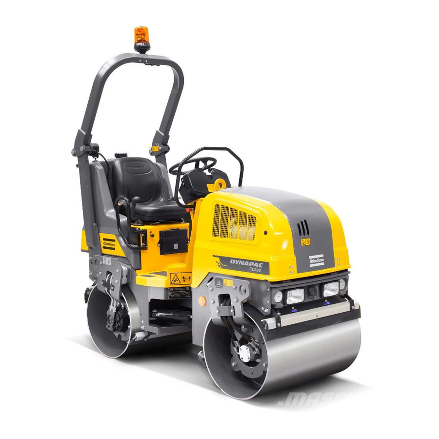
Introduction Introduction The machine Dynapac CC900 is a self-propelled vibratory tandem roller in the 1,6 metric tonnes class featuring 900 mm wide drums. The machine is equipped with drive, brakes, and vibration on both drums. Intended use CC900 is primarily used for smaller compaction works, such as minor roads, sidewalks, cycle ways and minor parking places. -
Page 10: General
Introduction Ensure good ventilation (extraction of air by fan) Ensure good ventilation (extraction of air by fan) where the engine is run indoors. where the engine is run indoors. Replace immediately the instruction manuals if Replace immediately the instruction manuals if lost, damaged or unreadable. -
Page 11: Ce Marking And Declaration Of Conformity
Introduction maintenance normally carried out by the operator. Additional instructions for the engine can be Additional instructions for the engine can be found in the manufactuer's engine manual. found in the manufactuer's engine manual. CE marking and Declaration of conformity (Applies to machines marketed in EU/EEC) This machine is CE marked. - Page 12 Introduction ICC900-2EN3.pdf 2012-02-23...
-
Page 13: Safety - General Instructions
Safety - General instructions Safety - General instructions (Also read the safety manual) The operator must be familiar with the contents of the OPERATION section The operator must be familiar with the contents of the OPERATION section before starting the roller. before starting the roller. - Page 14 Safety - General instructions 16. Hearing protection is recommended if the noise level exceeds 85 dB(A). The 16. Hearing protection is recommended if the noise level exceeds 85 dB(A). The noise level can vary depending on the equipment on the machine and the noise level can vary depending on the equipment on the machine and the surface the machine is being used on.
-
Page 15: Safety - When Operating
Safety - when operating Safety - when operating Prevent persons from entering or remaining in Prevent persons from entering or remaining in the danger area, i.e. a distance of at least 7 m the danger area, i.e. a distance of at least 7 m (23 ft) in all directions from operating machines. -
Page 16: Driving Near Edges
Safety - when operating Driving near edges When driving near an edge, minimum 2/3 of the drum width must be on solid ground. Keep in mind that the machine’s center of Keep in mind that the machine’s center of gravity moves outwards when steering. For gravity moves outwards when steering. -
Page 17: Sitting Position
Safety - when operating Sitting position Remain seated at all times when operating the roller. If the operator stands up during operation, a buzzer sounds. After 4 seconds the brakes are activated and the engine stops. Brace yourself for a sudden stop. Always use the seat belt where fitted. - Page 18 Safety - when operating ICC900-2EN3.pdf 2012-02-23...
-
Page 19: Special Instructions
Special instructions Special instructions Standard lubricants and other recommended oils and fluids Before leaving the factory, the systems and components are filled with the oils and fluids specified in the lubricant specification. These are suitable for ambient temperatures in the range -15°C to +40°C (5°F - 104°F). -
Page 20: Fire Fighting
Special instructions Fire fighting If the machine catches fire, use an ABC-class powder fire extinguisher. A BE-class carbon dioxide fire extinguisher can also be used. Roll Over Protective Structure (ROPS), ROPS approved cab If the machine is fitted with a Roll Over If the machine is fitted with a Roll Over Protective Structure (ROPS, or ROPS approved Protective Structure (ROPS, or ROPS approved... -
Page 21: Jump Starting
Special instructions Jump starting Do not connect the negative cable to the Do not connect the negative cable to the negative terminal on the dead battery. A spark negative terminal on the dead battery. A spark can ignite the oxy-hydrogen gas formed can ignite the oxy-hydrogen gas formed around the battery. - Page 22 Special instructions ICC900-2EN3.pdf 2012-02-23...
-
Page 23: Technical Specifications
Technical specifications Technical specifications Vibrations - Operator station (ISO 2631) The vibration levels are measured in accordance with the operational cycle described in The vibration levels are measured in accordance with the operational cycle described in EU directive 2000/14/EC on machines equipped for the EU market, with vibration switched EU directive 2000/14/EC on machines equipped for the EU market, with vibration switched on, on soft polymer material and with the operator’s seat in the transport position. - Page 24 Technical specifications ICC900-2EN3.pdf 2012-02-23...
-
Page 25: Technical Specifications - Dimensions
Technical specifications - Dimensions Technical specifications - Dimensions Dimensions, side view Dimensions Dimensions 1350 1350 53.2 53.2 2300 2300 90.6 90.6 1520 1520 59.8 59.8 18.3 18.3 2095 2095 82.5 82.5 2040 2040 80.3 80.3 0.51 0.51 2012-02-23 ICC900-2EN3.pdf... -
Page 26: Dimensions, Top View
Technical specifications - Dimensions Dimensions, top view Dimensions Dimensions 38.4 38.4 2700 2700 106.3 106.3 2660 2660 104.7 104.7 35.4 35.4 ICC900-2EN3.pdf 2012-02-23... -
Page 27: Weights And Volumes
Technical specifications - Dimensions Weights and volumes Weights Weights Service weight with ROPS Service weight with ROPS 1580 kg 1580 kg 3,483 lbs 3,483 lbs (EN500) (EN500) Fluid volumes Fluid volumes Fuel tank Fuel tank 23 liters 23 liters 6,0 gal 6,0 gal Water tank Water tank... -
Page 28: Tightening Torque
Technical specifications - Dimensions Tightening torque Tightening torque in Nm (lbf.ft) for oiled or dry bolts tightened with a torque wrench. Metric coarse screw thread, bright galvanized (fzb): STRENGTH CLASS: 8.8, Oiled 8.8, Oiled 8.8, Dry 8.8, Dry 10.9, Oiled 10.9, Oiled 10.9, Dry 10.9, Dry... -
Page 29: Rops - Bolts
Technical specifications - Dimensions ROPS-bolts which are to be torque tightened ROPS-bolts which are to be torque tightened must be dry. must be dry. ROPS - bolts Bolt dimensions : Bolt dimensions : M12 (PN 508063) M12 (PN 508063) Strength class : Strength class : Tightening torque : Tightening torque :... - Page 30 Technical specifications - Dimensions ICC900-2EN3.pdf 2012-02-23...
-
Page 31: Machine Description
Machine description Machine description Identification Product identification number on the frame The machine PIN (Product Identification Number) (1) is punched on the right edge of the front frame. Fig. PIN right side Fig. PIN front right 2012-02-23 ICC900-2EN3.pdf... -
Page 32: Machine Plate
Machine description Machine plate The machine plate (1) is attached to the front right side of the rear frame, beside the steering joint. The plate specifies the manufacturers name and address, the type of machine, the PIN, Product Identification Number (serial number), operating weight, engine power and year of manufacture. -
Page 33: Engine Plates
Machine description Engine plates The plates specify the type of engine, serial number and the engine specification. Figure. EPA plate on 403C-11 Fig. Engine 1. EPA plate 2. Type plate Figure. EPA plate on 403D-11 The engine type plate (2) is attached to the top of the engine. - Page 34 Machine description- Decals ICC900-2EN3.pdf 2012-02-23...
-
Page 35: Machine Description- Decals
Machine description- Decals Machine description- Decals Location - decals 5, 8 1, 6 Fig. Location, decals and signs Warning, Risk of being crushed Warning, Risk of being crushed 4700903422 4700903422 Lifting point Lifting point 4700357587 4700357587 Warning, Rotating engine components Warning, Rotating engine components 4700903423 4700903423... -
Page 36: Safety Decals
Machine description- Decals Safety decals 4700903422 Warning - Crush zone, articulation/drum. Maintain a safe distance from the crush zone. (Two crush zones on machines fitted with pivotal steering) 4700903423 Warning - Rotating engine components. Keep your hands at a safe distance from the danger zone. -
Page 37: Info Decals
Machine description- Decals 4700791642 Warning - Starting gas Starting gas is not to be used. Info decals Noise power level Noise power level Diesel fuel Diesel fuel Lifting point Lifting point Hoisting plate Hoisting plate Handbook compartment Handbook compartment Battery isolation switch Battery isolation switch Hydraulic oil level Hydraulic oil level... -
Page 38: Instruments/Controls
Machine description- Decals Instruments/Controls Locations - Instruments and controls Fig. Instruments and control panel Manual/automatic sprinkler Manual/automatic sprinkler Hazard beacon Hazard beacon Sprinkler timer Sprinkler timer Direction indicators Direction indicators Road lights Road lights Horn Horn Working lights Working lights Vibration manual/automatic Vibration manual/automatic Hazard warning lights... -
Page 39: Locations - Control Panel And Controls
Machine description- Decals Locations - Control panel and controls Fig. Control panel Fig. Operator's station Fig. Operator position Starter switch Starter switch Low fuel level Low fuel level Engine speed control Engine speed control Oil pressure, engine Oil pressure, engine Emergency stop Emergency stop Parking brake lamp... -
Page 40: Function Description
Machine description- Decals Function description Designation Designation Symbol Symbol Function Function Starter switch Starter switch Positions 1-2: Shut off position, key can be Positions 1-2: Shut off position, key can be removed. removed. Position 3a: All instruments and electric controls Position 3a: All instruments and electric controls are supplied with power. - Page 41 Machine description- Decals Designation Designation Symbol Symbol Function Function Road lights, Road lights, switch switch Where the upper position is depressed, the road Where the upper position is depressed, the road (Optional) (Optional) lights are on. Where the lower position is, lights are on.
- Page 42 Machine description- Decals ICC900-2EN3.pdf 2012-02-23...
-
Page 43: Electrical System
Machine description- Decals Electrical system Fuses The figure shows the position of the fuses. The table below gives fuse amperage and function. All fuses are flat pin fuses. Fig. Fuse box Fuses in the fusebox Fuses in the fusebox ECU Instrument panel, sprinkler ECU Instrument panel, sprinkler Hazard beacon Hazard beacon... - Page 44 Machine description- Decals ICC900-2EN3.pdf 2012-02-23...
-
Page 45: Operation
Operation Operation Before starting Battery isolation switch - On - Optional Remember to carry out daily maintenance. Refer to the maintenance instructions. The battery isolation switch is located in the engine compartment. Turn the key (1) to the on position. The entire roller is now supplied with power. -
Page 46: Driver Seat (Option)- Adjustment
Operation Driver seat (Option)- Adjustment Adjust the operator’s seat so that the position is comfortable and so that the controls are within easy reach. The seat can be adjusted as follows. - Length adjustment (1) - Weight adjustment (2) Fig. Driver seat - Back support angle (3) 1. -
Page 47: Interlock
Operation Interlock The roller is equipped with Interlock. The engine switches off 4 seconds after the operator rises from the seat. The engine stops whether the forward/reverse lever is in the neutral or the drive position. The engine does not stop if the parking brake is activated. -
Page 48: Starting
Operation roller, always wear the seat belt (1) provided and wear a protective helmet. Starting Starting the engine The operator must remain seated when starting. The operator must remain seated when starting. Make sure that the emegency stop button (3) is pulled out and the parking brake (31) is activated. - Page 49 Operation Check while warming the engine that the warning lamps for the oil pressure (24) and charging (28) go out. The warning lamp (25) should remain on. When starting and driving a machine that is cold, When starting and driving a machine that is cold, remember that the hydraulic fluid is also cold and remember that the hydraulic fluid is also cold and that braking distances can be longer than normal...
-
Page 50: Driving
Operation Driving Operating the roller Under no circumstances is the machine to be Under no circumstances is the machine to be operated from the ground. The operator must be operated from the ground. The operator must be seated inside the machine during all operation. seated inside the machine during all operation. -
Page 51: Interlock/Emergency Stop/Parking Brake - Check
Operation Interlock/Emergency stop/Parking brake - Check The interlock, emergency stop and parking brake must The interlock, emergency stop and parking brake must be checked daily before operating. A function check of be checked daily before operating. A function check of the interlock and emergency stop requires a restart. -
Page 52: Vibration
Operation Vibration Manual/Automatic vibration Manual or automatic vibration activation/deactivation is selected using switch (20). In the manual position, the operator must activate the vibration using the switch(4) on underside of the forward/reverse lever grip. In the automatic position, vibration is activated when the pre-set speed is reached. -
Page 53: Emergency Braking
Operation Emergency braking There is a brake in each drum motor that acts as an emergency brake during operation. To brake in an emergency situation, push in the To brake in an emergency situation, push in the emergency stop knob (3), hold the steering wheel emergency stop knob (3), hold the steering wheel firmly and be prepared for a sudden stop. -
Page 54: Parking
Operation Parking Chocking the drums Never leave the operator platform without Never leave the operator platform without activating the parking brake (31). activating the parking brake (31). Make sure that the roller is parked in a safe place Make sure that the roller is parked in a safe place with respect to other road users. -
Page 55: Long-Term Parking
Long-term parking Long-term parking The following instructions should be followed The following instructions should be followed when long term parking (more than one month). when long term parking (more than one month). These measures apply when parking for a period of up to 6 months. -
Page 56: Hydraulic Reservoir
Long-term parking Hydraulic reservoir Fill the hydraulic reservoir to the uppermost level mark (see under the heading ‘Every 10 hours of operation.’) Steering cylinder, hinges, etc. Grease the steering cylinder piston with conservation grease. Grease the hinges on the doors to the engine compartment. -
Page 57: Miscellaneous
Miscellaneous Miscellaneous Lifting Locking the articulation Before lifting the roller the steering joint must be Before lifting the roller the steering joint must be locked to prevent it turning. locked to prevent it turning. Turn the steering wheel to the straight ahead position. Switch off the machine. -
Page 58: Unlocking The Articulation
Miscellaneous Unlocking the articulation Remember to unlock the articulation before Remember to unlock the articulation before operating. operating. Pull out the locking pin (1), turn the locking arm (2) for the rear frame, secure the locking arm by inserting the locking bolt (3) through the mounting in the rear frame and locking arm. -
Page 59: Transport
Transport Transport Roller prepared for transport Lock the articulation before lifting and Lock the articulation before lifting and transporting. Follow the instructions under the transporting. Follow the instructions under the relevant heading. relevant heading. Chock the drums (1) and secure the chocks to the transport vehicle. -
Page 60: Towing/Recovering
Transport Towing/Recovering The roller can be moved up to 300 meters (1,000 ft) using the instructions below. Switch off the diesel engine and push in the Switch off the diesel engine and push in the emergency stop knob. Chock the drum to prevent emergency stop knob. -
Page 61: Towing The Roller
Transport Tightening torque Tightening torque Screws (192) Screws (192) Plugs (191) Plugs (191) Towing the roller A towing bar must be used when towing, as the A towing bar must be used when towing, as the roller has no brakes and can only be slowed and roller has no brakes and can only be slowed and stopped by the vehicle towing the roller. - Page 62 Operating instructions - Summary ICC900-2EN3.pdf 2012-02-23...
-
Page 63: Operating Instructions - Summary
Operating instructions - Summary Operating instructions - Summary Follow the SAFETY INSTRUCTIONS specified in the Safety Manual. Follow the SAFETY INSTRUCTIONS specified in the Safety Manual. Make sure that all instructions in the MAINTENANCE section are followed. Make sure that all instructions in the MAINTENANCE section are followed. Turn the master switch to the ON position. - Page 64 Operating instructions - Summary ICC900-2EN3.pdf 2012-02-23...
-
Page 65: Preventive Maintenance
Preventive maintenance Preventive maintenance Complete maintenance is necessary for the machine to function satisfactorily and at the lowest possible cost. The Maintenance section includes the periodic maintenance that must be carried out on the machine. The recommended maintenance intervals assume that the machine is used in a normal environment and working conditions. - Page 66 Preventive maintenance ICC900-2EN3.pdf 2012-02-23...
-
Page 67: Maintenance - Lubricants And Symbols
Maintenance - Lubricants and symbols Maintenance - Lubricants and symbols Fluid volumes Fluid volumes Hydraulic reservoir Hydraulic reservoir 12 liters 12 liters 3,2 gal 3,2 gal Engine Engine 4,7 liters 4,7 liters 5,0 qts 5,0 qts Drum Drum 3,5 liters 3,5 liters 3,7 qts 3,7 qts... -
Page 68: Maintenance Symbols
Maintenance - Lubricants and symbols Other fuel and lubricants are required when Other fuel and lubricants are required when operating in areas with extremely high or operating in areas with extremely high or extremely low ambient temperatures. See the extremely low ambient temperatures. See the ‘Special instructions’... -
Page 69: Maintenance - Maintenance Schedule
Maintenance - Maintenance schedule Maintenance - Maintenance schedule Service and maintenance points Fig. Service and maintenance points Water tank, filling Water tank, filling Air cleaner Air cleaner 13. Hydraulic fluid, filling 13. Hydraulic fluid, filling Forward/Reverse lever Forward/Reverse lever Battery (maintenance free) Battery (maintenance free) 14. -
Page 70: General
Maintenance - Maintenance schedule General Periodic maintenance should be carried out after the number of hours specified. Use the daily, weekly etc. periods where number of hours cannot be used. Remove all dirt before filling, when checking Remove all dirt before filling, when checking oils and fuel and when lubricating using oil or oils and fuel and when lubricating using oil or grease. -
Page 71: After The First 50 Hours Of Operation
Maintenance - Maintenance schedule After the FIRST 50 hours of operation Refer to the contents to find the page number of the sections referred to ! Action Action Comment Comment Change the fuel filter Change the fuel filter Refer to the engine manual Refer to the engine manual Change the engine oil and oil filter Change the engine oil and oil filter... -
Page 72: Every 500 Hours Of Operation (Yearly)
Maintenance - Maintenance schedule Every 500 hours of operation (Yearly) Refer to the contents to find the page number of the sections referred to ! Pos. Pos. Action Action Comment Comment in fig in fig Replace the air cleaner filter element, check that Replace the air cleaner filter element, check that hoses and connectors are tight hoses and connectors are tight... -
Page 73: Maintenance - 10H
Maintenance - 10h Maintenance - 10h Park the roller on a level surface. Park the roller on a level surface. The engine must be switched off and the The engine must be switched off and the parking brake activated when checking or parking brake activated when checking or adjusting the roller, unless otherwise specified. -
Page 74: Check - Coolant System
Maintenance - 10h Check - Coolant system Check that all hoses/hose connectors are intact and tight. Fill with coolant as specified in the lubricants specification. Take great care when opening the radiator cap Take great care when opening the radiator cap while the engine is hot. -
Page 75: Water Tank - Filling
Maintenance - 10h Water tank - Filling Unscrew the tank cap (1), and fill with clean water. Unscrew the tank cap (1), and fill with clean water. Fill the water tank; it holds 110 liters. Only additive: A small amount of environmentally Only additive: A small amount of environmentally friendly antifreeze. -
Page 76: Air Circulation - Check
Maintenance - 10h Air circulation - Check Check that the circulation of air to the engine through the grille in the engine cover is unobstructed. Fig. Engine cover 1. Cooling air grille/engine Scrapers - Check, adjustment Make sure that the scrapers are undamaged. Adjust the scrapers if necessary in the following way: For firmer application of the scraper, undo the locking nut (2) and adjust it until the desired application is... -
Page 77: Check - Drainage - Water Separator
Maintenance - 10h Check - Drainage - Water separator Unscrew the cup (2) and empty. Deliver the drained fluid to waste handling. Deliver the drained fluid to waste handling. Fig. Water separator 1. Water separator 2. Cup Air cleaner indicator If the indicator (1) on the air cleaner is red, the air cleaner dust trap (2) must be emptied. -
Page 78: Refueling
Maintenance - 10h Refueling Refuel the tank every day before starting work. Open the tank cap and fill through the filler pipe (1). Never refuel while the engine is running. Do not Never refuel while the engine is running. Do not smoke and avoid spilling fuel. -
Page 79: Maintenance - 50H
Maintenance - 50h Maintenance - 50h Park the roller on a level surface. Park the roller on a level surface. The engine must be switched off and the The engine must be switched off and the parking brake activated when checking or parking brake activated when checking or adjusting the roller, unless otherwise specified. -
Page 80: Air Cleaner - Emptying
Maintenance - 50h Air cleaner - emptying Empty the air cleaner dust trap (1) through pressing the rubber bellows using the fingers. Check also that the air hoses are intact. Clean the air cleaner when operated in extremely dusty environments . Refer also to the section in the manual on operation. -
Page 81: Maintenance - 250H
Maintenance - 250h Maintenance - 250h Park the roller on a level surface. Park the roller on a level surface. The engine must be switched off and the The engine must be switched off and the parking brake activated when checking or parking brake activated when checking or adjusting the roller, unless otherwise specified. -
Page 82: Hydraulic Fluid Cooler - Cleaning
Maintenance - 250h Hydraulic fluid cooler - Cleaning Clean the hydraulic fluid cooler’s cooling flanges, ideally with compressed air. Blow the cooler clean by blowing air from the inside outwards. Wear gloves and eye protectors when working Wear gloves and eye protectors when working with compressed air. -
Page 83: Alternator Belt - Checking Tension - Change
Maintenance - 250h Alternator belt - checking tension - Change Switch off the engine, disconnect the power and Switch off the engine, disconnect the power and switch on the emergency brake button. switch on the emergency brake button. If the alternator belt (3) can be pressed in by hand around 10 mm at a position half way between the pulleys, it is correctly tensioned. - Page 84 Maintenance - 250h ICC900-2EN3.pdf 2012-02-23...
-
Page 85: Maintenance - 500H
Maintenance - 500h Maintenance - 500h Park the roller on a level surface. Park the roller on a level surface. The engine must be switched off and the The engine must be switched off and the parking brake activated when checking or parking brake activated when checking or adjusting the roller, unless otherwise specified. -
Page 86: Hydraulic Reservoir - Check/Venting
Maintenance - 500h Hydraulic reservoir - Check/venting Unscrew and make sure that the reservoir cap is not blocked. Air must have unobstructed passage through the cap in both directions. If blocked in either direction, clean with a little diesel oil and blow with compressed air until unblocked or replace the cap with a new one. -
Page 87: Engine Oil And Oil Filter - Change
Maintenance - 500h Engine oil and oil filter - Change Run the engine until it is warm before draining the oil . Switch off the engine and push in the emergency Switch off the engine and push in the emergency brake button. -
Page 88: Check - Coolant System
Maintenance - 500h Check - Coolant system Check that all hoses/hose connectors are intact and tight. Fill with coolant as specified in the lubricants specification. Take great care when opening the radiator cap Take great care when opening the radiator cap while the engine is hot. -
Page 89: Maintenance - 1000H
Maintenance - 1000h Maintenance - 1000h Park the roller on a level surface. Park the roller on a level surface. The engine must be switched off and the The engine must be switched off and the parking brake activated when checking or parking brake activated when checking or adjusting the roller, unless otherwise specified. -
Page 90: Alternator Belt - Checking Tension - Change
Maintenance - 1000h Check the hydraulic oil level in the sight glass (1) and top off where necessary. See under the heading ‘Every 10 hours of operation’. Fig. Engine compartment, right side 1. Sight glass Alternator belt - Checking tension - Change Switch off the engine, disconnect the power and Switch off the engine, disconnect the power and switch on the emergency brake button. -
Page 91: Maintenance - 2000H
Maintenance - 2000h Maintenance - 2000h Park the roller on a level surface. Park the roller on a level surface. The engine must be switched off and the The engine must be switched off and the parking brake activated when checking or parking brake activated when checking or adjusting the roller, unless otherwise specified. -
Page 92: Water Tank - Cleaning
Maintenance - 2000h Water tank - Cleaning Keep in mind that there is a risk of freezing in Keep in mind that there is a risk of freezing in winter. Drain the tank, pump and lines. winter. Drain the tank, pump and lines. Drain the tank through the drainage tap (1) alongside the filter. -
Page 93: Steering Joint - Check
Maintenance - 2000h Steering joint - Check Inspect the steering joint to detect any damage or cracks. Check and tighten any loose bolts. Check also for any stiffness and play in the steering joint. Rectify if necessary. Fig. Steering joint 2012-02-23 ICC900-2EN3.pdf... -
Page 94: Hydraulic Reservoir - Fluid Change
Maintenance - 2000h Hydraulic reservoir - fluid change Use an external drainage pump when draining/emptying the hydraulic reservoir. Risk of burn injuries when draining hot oil. Wear Risk of burn injuries when draining hot oil. Wear protective gloves and goggles. protective gloves and goggles. - Page 95 Dynapac Compaction Equipment AB Box 504, SE-371 23 Karlskrona, Sweden...
- Page 96 Dynapac Compaction Equipment AB Box 504, SE-371 23 Karlskrona, Sweden...
Need help?
Do you have a question about the DYNAPAC CC900 and is the answer not in the manual?
Questions and answers