
Related Manuals for ICP DAS USA CL-201-WF


Summary of Contents for ICP DAS USA CL-201-WF
- Page 1 CL-200 Series User Manual Remote CO/CO2/NH3/H2S/HCHO/TVOC/ Temperature/Humidity/Dew Point Data Logger Module Version: 1.2.0 Date: Feb. 2019...
- Page 2 Warranty All products manufactured by ICP DAS are warranted against defective materials for a period of one year from the date of delivery to the original purchaser. Warning ICP DAS assumes no liability for damages consequent to the use of this product. ICP DAS reserves the right to change this manual at any time without notice.
-
Page 3: Table Of Contents
Contents 1. Introduction ..........................5 2. Hardware ..........................10 2.1 Specifications ......................... 10 2.2 Appearance ........................28 2.3 Dimensions (unit: mm) ....................30 2.4 Cabling for Power and Network ..................31 3. Configuration via Web Browser ....................36 3.1 Search the CL-200 logger ....................36 3.2 Logging into the CL-200 .................... - Page 4 A-5. CL-205-E DCON Command Sets ................107 A-6. CL-206-E DCON Command Sets ................112 A-7. CL-207-E DCON Command Sets ................117 A-8. CL-208-E DCON Command Sets ................122 A-9. CL-210-E DCON Command Sets ................127 A-10. CL-211 / CL-211-E DCON Command Sets ............132 A-11.
-
Page 5: Introduction
1. Introduction The CL-200 series of data logger devices can be used to record PM2.5, CO, CO2, H2S, NH3, HCHO, TVOC, temperature, humidity and dew point information, including the date and time stamps, and are able to store up to 450,000 downloadable records. Real-time data can be accessed from the CL-200 data logger from anywhere and at any time using the free Windows software, the iOS App, or the Android App, as long as they are connected to the same local network as the data logger. - Page 6 Characteristics PM2.5 measurement range: 0 to 400 ug/m CO measurement range: 0 to 1000 ppm measurement range: 0 to 9999 ppm NH3 measurement range: 0 to 100 ppm H2S measurement range: 0 to 100 ppm HCHO measurement range: 0 to 2000 ppb TVOC measurement range: 0 to 60000 ppb Non‐dispersive Infrared (NDIR) sensor with Automatic Baseline Correction algorithm for CO...
- Page 7 Features NDIR Sensor NDIR (Non-Dispersion Infrared) is based on one of the natural properties of CO molecules: CO molecules absorb light at a specific wavelength of 4.26 µm. This wavelength is in the infrared (IR) range. High concentrations of CO molecules absorb more light than low concentrations.
- Page 8 Easy integration with SCADA software Modbus is one of the most popular protocols used in the industrial world. Supporting traditional serial protocols of RS-485 and Ethernet protocols allow the CL-200 series well-integrated into the HMI/SCADA systems. Alarm CL-200 series allows users to set high alarm level for PM2.5/CO/CO /H2S/NH3/ HCHO/TVOC/Temperature/Humidity/Dew Point...
- Page 9 Support for MQTT protocol Smartphone MQTT is a protocol designed for the CL-203-E MQTT efficient exchange of real-time data Mobile Tablet Broker with sensor and mobile devices. It CL-212-E runs over TCP/IP and is in widest Subscriber use on the "machine-to-machine" (M2M) and "Internet of Things"...
-
Page 10: Hardware
2. Hardware 2.1 Specifications Model CL-201-E CL-201-BLE CL-201-WF CO Measurement 0 to 1000 ppm (Electrochemical) Range 1 ppm Resolution ±5% of measured value Accuracy 30 seconds Response Time 60 seconds Warm-up Time Temperature Measurement Range -10 to +50°C Resolution 0.1°C Accuracy ±0.6°C... - Page 11 Wireless Security AES 128 WEP, WPA ,WPA2 Transmission Range 20 m (LOS) 50 m (LOS) Electrical Powered via Terminal +12 to +48 VDC Block Powered via PoE IEEE 802.3af, Class 1 (require a PoE switch or injector) 1.7 W 1.8 W 1.9 W Power Consumption Mechanical...
- Page 12 System CO Alarm Alarm PM2.5 Alarm Real Time Clock Data Logger Yes, 450,000 Records Alarm Relay Output Form A×1, SPST. 30 VDC @ 16 A or 250 VAC @ 16 A Communication DCON, Modbus RTU, Modbus TCP, MQTT Protocol Wire Interface Yes, RS-485 X 1 and Ethernet/PoE X1 Wireless Interface Bluetooth...
- Page 13 Model CL-203-E CL-203-BLE CL-203-WF CO Measurement 0 to 1000 ppm (Electrochemical) Range 1 ppm Resolution ±5% of measured value Accuracy 30 seconds Response Time 60 seconds Warm-up Time Measurement Range 0 ~ 9999 ppm Resolution 1 ppm Accuracy ±40 ppm ±3% Response Time 120 seconds Warm-up Time...
- Page 14 Standard Supported BT 4.0 IEEE 802.11 b/g/n Infrastructure/ Wireless Mode Slave Limited AP Wireless Security AES 128 WEP, WPA ,WPA2 Transmission Range 20 m (LOS) 50 m (LOS) Electrical Powered via Terminal +12 to +48 VDC Block Powered via PoE IEEE 802.3af, Class 1 (require a PoE switch or injector) 1.8 W 1.9 W...
- Page 15 Relative Humidity Measurement Range 0 to 100% RH, Non-condensing Resolution 0.1% RH, Non-condensing Accuracy ±5% RH, Non-condensing Dew Point Range Calculated using temperature and relative humidity Resolution 0.1°C System HCHO Alarm TVOC Alarm PM2.5 Alarm Real Time Clock Data Logger Yes, 450,000 Records Alarm Relay Output Form A×1, SPST.
- Page 16 Model CL-205-E CL-205-BLE CL-205-WF NH3 Measurement 0 to 100 ppm (Electrochemical) Range 1 ppm Resolution ± 5% of measured value Accuracy < 120 Sec Response Time 180 Sec Warm-up Time Temperature Measurement Range -10 to +50°C Resolution 0.1°C Accuracy ±0.6°C Relative Humidity Measurement Range 0 to 100% RH, Non-condensing...
- Page 17 Powered via PoE IEEE 802.3af, Class 1 (require a PoE switch or injector) 1.9 W 2.2 W 2.2 W Power Consumption Mechanical Dimensions (D x H) Ø 150 mm x 53 mm Installation Ceiling Mounting or Wall Mounting Environment Operating 0 to +50°C Temperature Storage Temperature...
- Page 18 Communication DCON, Modbus RTU, Modbus TCP, MQTT Protocol Wire Interface Yes, RS-485 X 1 and Ethernet/PoE X1 Wireless Interface Bluetooth Wi-Fi Standard Supported BT 4.0 IEEE 802.11 b/g/n Infrastructure/ Wireless Mode Slave Limited AP Wireless Security AES 128 WEP, WPA ,WPA2 Transmission Range 20 m (LOS) 50 m (LOS)
- Page 19 Resolution 0.1% RH, Non-condensing Accuracy ±5% RH, Non-condensing Dew Point Range Calculated using temperature and relative humidity Resolution 0.1°C System HCHO Alarm PM2.5 Alarm Real Time Clock Data Logger Yes, 450,000 Records Alarm Relay Output Form A×1, SPST. 30 VDC @ 16 A or 250 VAC @ 16 A Communication DCON, Modbus RTU, Modbus TCP, MQTT Protocol...
- Page 20 Model CL-208-E CL-208-BLE CL-208-WF TVOC Measurement 0 to 60000 ppb (MEMS Metal Oxide) Range Resolution 1 ppb ± 15% Accuracy 60 seconds Response Time 180 seconds Warm-up Time Temperature Measurement Range -10 to +50°C Resolution 0.1°C Accuracy ±0.6°C Relative Humidity Measurement Range 0 to 100% RH, Non-condensing Resolution...
- Page 21 Electrical Powered via Terminal +12 to +48 VDC Block Powered via PoE IEEE 802.3af, Class 1 (require a PoE switch or injector) 1.9 W 2.0 W 2.0 W Power Consumption Mechanical Dimensions (D x H) Ø 150 mm x 53 mm Installation Ceiling Mounting or Wall Mounting Environment...
- Page 22 Communication DCON, Modbus RTU, Modbus TCP, MQTT Protocol Wire Interface Yes, RS-485 X 1 and Ethernet/PoE X1 Wireless Interface Bluetooth Wi-Fi Standard Supported BT 4.0 IEEE 802.11 b/g/n Infrastructure/ Wireless Mode Slave Limited AP Wireless Security AES 128 WEP, WPA ,WPA2 Transmission Range 20 m (LOS) 50 m (LOS)
- Page 23 Temperature Measurement Range -10 to +50°C Resolution 0.1°C Accuracy ±0.6°C Relative Humidity Measurement Range 0 to 100% RH, Non-condensing Resolution 0.1% RH, Non-condensing Accuracy ±5% RH, Non-condensing Dew Point Range Calculated using temperature and relative humidity Resolution 0.1°C System CO Alarm Alarm PM2.5 Alarm Real Time Clock...
- Page 24 Installation Ceiling Mounting or Wall Mounting Environment Operating 0 to +50°C Temperature Storage Temperature -30 to +75°C Humidity 10 to 90% RH, Non-condensing Model CL-212 CL-212-E CL-212-BLE CL-212-WF PM2.5 Measurement 0 to 400 ug/m Range 1ug/m Resolution <=1 min. Response Time Measurement Range 0 ~ 9999 ppm...
- Page 25 Alarm Relay Output Form A×1, SPST. 30 VDC @ 16 A or 250 VAC @ 16 A Communication DCON, Modbus DCON, Modbus RTU, Modbus TCP, MQTT Protocol Wire Interface Yes, RS-485 X 1 Yes, RS-485 X 1 and Ethernet/PoE X1 Wireless Interface Bluetooth Wi-Fi...
- Page 26 30 seconds Response Time 60 seconds Warm-up Time Measurement Range 0 ~ 9999 ppm Resolution 1 ppm Accuracy ±40 ppm ±3% Response Time 120 seconds Warm-up Time 5 minutes Temperature Measurement Range -10 to +50°C Resolution 0.1°C Accuracy ±0.6°C Relative Humidity Measurement Range 0 to 100% RH, Non-condensing Resolution...
- Page 27 Transmission Range 20 m (LOS) 50 m (LOS) Electrical Powered via Terminal +10 to +30 +12 to +48 VDC Block IEEE 802.3af, Class 1 (require a PoE switch or Powered via PoE injector) 1.2 W 2.1 W 2.2 W 2.2 W Power Consumption Mechanical Dimensions (D x H)
-
Page 28: Appearance
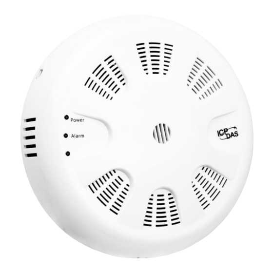
2.2 Appearance Internal Wi-Fi Antenna (For CL-200-WF Only) LED Indicators: Power Alarm Rotary Switch DIP Switch Connectors: Power RS-485 PoE/Non-PoE Alarm Relay Output Ethernet Port LED Indicators PWR: Red for normal operation. Alarm: Green for alarm condition. DIP Switch The functions are printed on the right beside the SW1 DIP switch. PoE/ non-PoE Ethernet port The Ethernet port can be used to connect to a PoE switch or a non-PoE switch. - Page 29 Connector for Power/ Frame Ground / RS-485/ Alarm Relay Output The Push-in connector can easily connect and detach solid wires or wires with wire-end ferrules without using tools. Just push in the solid wire to lock it and press the white button to release the wire.
-
Page 30: Dimensions (Unit: Mm)
2.3 Dimensions (unit: mm) CL-200 Series User Manual Version 1.2.0 Apr. 2019 - 30 -... -
Page 31: Cabling For Power And Network
2.4 Cabling for Power and Network Note Do not install the CL-200 module near a vent, a ventilation fan or a door where the air flows faster. Avoid installing in locations where the temperature is below 0°C or above 50°C. ... - Page 32 The iAir App and DL-300 Utility search the logger by broadcast, therefore only the devices on the same subnet can be searched out. It means that the host PC, Android devices and the logger must have the same broadcast address. The broadcast address for an IPv4 device can be obtained by performing a bitwise OR operation between the bit complement of the subnet mask and the IP address for a device.
- Page 33 For connecting with PC via Wi-Fi The CL-200-WF logger can connect to the PC through Wi-Fi with power input requirement of +12 ~ +48 V The CL-200-WF device can be configured as station mode, such that the PC/Laptop can be connected through Wi-Fi AP. The CL-200-WF device can be configured as AP mode, such that the PC/Laptop can be connected through Wi-Fi directly.
- Page 34 2.5 Hardware Mounting CL-200 Series User Manual Version 1.2.0 Apr. 2019 - 34 -...
- Page 35 (Requires RJ45 Cable, Male-Female, 30cm (90º)) CL-200 Series User Manual Version 1.2.0 Apr. 2019 - 35 -...
-
Page 36: Configuration Via Web Browser
3. Configuration via Web Browser CL-200 logger has a built-in web server that provides simple web pages for remote monitoring real-time data and configuring the logger with a standard browser. For opening the web page in CL-200, the factory default IP address (192.168.255.1), Subnet Mask (255.255.0.0) and Gateway (192.168.0.1) need be set to available IP/Subnet Mask/Gateway addresses in your Ethernet environment. -
Page 37: Logging Into The Cl-200
3. Set available IP Address, Sub-net Mask, Gateway (designated by your network administrator) and alias and click the OK button. The Alias for easy to identify each item will be shown at the bottom-left corner of the CL-200 screen. 3.2 Logging into the CL-200 1. -
Page 38: Home
3.3 Home The first page displayed is Home, it shows the based configuration of the CL-200 module and the real-time data as below: In the Sensor Readings field is the real-time data of PM2.5/CO/CO /NH3/H2S/HCHO /TVOC concentration, temperature, humidity and dew point, the minimum value (Low Latched) and maximum value (High Latched) logged. -
Page 39: Network
The Digital Output table shows the status of the relay output and the control button Set Digital Output to change the relay output status. The control function is invalid when any of the alarm modes is not disabled. If one of the alarm modes is enabled, the relay is linked to the alarm status for tapping audible/visual alarm. - Page 40 Item Description Default System Sets the timeout for rebooting a CL-200 logger when it is Timeout abnormal or failure to communicate. (Disable) (Network Watchdog) Range: 30 ~ 65535 (unit: second) 0 = Disable TCP Timeout Sets the timeout for disconnecting a TCP connection when a CL-200 does not receive data coming from the Ethernet port.
- Page 41 The Reboot button is used to reboot the CL-200. After pressing the button, a user needs to login the CL-200 logger again to using the web interface. The Restore Defaults button can be used to restore the following settings to factory default values.
-
Page 42: Mqtt
3.5 MQTT MQTT stands for MQ Telemetry Transport, it is a publish/subscribe, extremely simple and lightweight messaging protocol, designed for constrained devices and low-bandwidth, high-latency or unreliable networks. The Publish-Subscribe messaging pattern requires a message broker. The broker is responsible for distributing messages to interested clients based on the topic of a message. - Page 43 - Cycle: sets the time period for update the publish messages in millisecond. - Module Topic Name: sets the module topic name. - PM2.5/CO/CO /NH3/H2S/HCHO/TVOC/Relative Humidity/Temperature (°C)/ Temperature (°F)/ Dew Point (°C)/ Dew Point (°F) Sub Topic Name: sets the sub topic name for each item.
-
Page 44: I/O Settings
3.6 I/O Settings Users can change the temperature unit to Fahrenheit or Celsius in this field. To Enable/Disable the CO Automatic Baseline Correction function. Q & A Q: What is ABC (Automatic Baseline Correction)? A: ABC stands for the Automatic Baseline Correction which is used to adjust a shifted baseline to the carbon dioxide level in fresh air. - Page 45 All the settings take effect after clicking the Update Settings button. Item Description Default Alarm Mode Disabled - Disabled: Disables alarm function. - Momentary: If a measurement value higher than the High Alarm Limit or lower than the Low Alarm Limit, the alarm occurs until the measurement value is within a range from Low Alarm Limit to High Alarm Limit.
- Page 46 Limit Humidity/ Temperature/ Dew Point. Beep On Enable/disable beep on alarm for PM2.5 /CO /CO2 Alarm /Temp /RH /Dew point Beep On Sets the time for beeping alarm. Alarm Time Range: 1 ~ 250 (unit: second) 0 = disable the beeping alarm 251 = continue the beeping alarm without stop Set the Power On Value and Safe Value for the relay output, and the Host Watchdog Timeout timer for RS-485 communication;...
- Page 47 In this table it shows the settings for data logger. All the settings take effect after clicking the Update Settings button. Item Description Default Status - Running: the data logger is running - Stopped: the data logger is stopped Change Sets the mode for data logger Stop Logging...
- Page 48 Overwrite Sets whether to overwrite old data by new ones when the on Full memory for data storage is full. (Over the upper limit of 450,000.) - No: discards the new data (default) - Yes: overwrites the old data by new ones Sampling Sets the time interval for logging data.
-
Page 49: Filter Ip
3.7 Filter IP For limiting the devices to access the CL-200 logger, users can specifies particular devices by setting their IP addresses on this page. When the addresses are 0.0.0.0 from IP1 to IP5, all the devices can access the logger. Once any of the 5 IP address columns is set, only the device with which IP is saved in the list can assess the logger. -
Page 50: Change Password
3.8 Change Password On this page users can change the passwords for login the logger and locking the touch screen. The factory default for the CL-200 touch screen has no password protection. After setting the password for touch screen, each time whoever wants to change to settings from the touch screed, the password will be requested. -
Page 51: Logout
3.9 Logout Click the Logout on any page to logout the CL-200. CL-200 Series User Manual Version 1.2.0 Apr. 2019 - 51 -... -
Page 52: Wi-Fi
3.10 Wi-Fi For CL-200-WF module, the Wi-Fi related parameters can be set via the Wi-Fi page. This page including Wi-Fi Status and Wi-Fi Settings, each of which will be described in more detail below. Wi-Fi Status The following table provides an overview of the parameters contained in the Wi-Fi Status section: Item Description... - Page 53 Wi-Fi Settings The column of Current shows the current Wi-Fi settings. You can change the settings by changing the column of New. The following table provides an overview of the parameters contained in the Wi-Fi Settings section: Item Description This parameter is used to specify the Wi-Fi mode of the CL-200-WF device.
- Page 54 Each CL-200-WF device connected to the Wi-Fi network must have its own IP Address unique IP address. This parameter is used to assign a specific IP address. This parameter is used to assign the subnet mask for the CL-200-WF Subnet Mask device.
-
Page 55: Configuration Via Rs-485
4. Configuration via RS-485 The factory default settings for RS-485 communication Address: 192 Protocol: Modbus/RTU Baudrate: 9600 Parity: N,8,1 Response Delay (ms): 0 Note If there are multiple CL-200 loggers connected to the same RS-485 network, each logger needs be set with a unique RS-485 address. - Page 56 4. Select the COM Port number used to connect the CL-200 logger. 5. The Baud Rate is factory default to 9600 bps. 6. Select the Protocol tab and check the protocol that set in the logger. CL-200 Series User Manual Version 1.2.0 Apr.
- Page 57 7. Select the Format tab and check the parity that set in the logger. 8. Click the Start Search icon. 9. The CL-200 logger searched out will be listed as below. CL-200 Series User Manual Version 1.2.0 Apr. 2019 - 57 -...
- Page 58 10. Click the module name to configure the logger. Note The Protocol/Baud Rate/Parity/Checksum items marked with ”(INIT*)” means that when any of those items needs be modified, the pin 4.INIT needs to be set in ON position and power cycle the logger, then the item can be modified. After complete setting, set the pin 4.INIT back to OFF position and power cycle the logger again to take the setting effect.
- Page 59 PM2.5/CO Degree of offset level Humidity、Temperature and Clear High/Low Dew point temperature Alarm Latch CL-200 Series User Manual Version 1.2.0 Apr. 2019 - 59 -...
- Page 60 Alarm tab Low Limit Alarm Buzzer On Alarm Mode High Limit Set Alarm Configurations CL-200 Series User Manual Version 1.2.0 Apr. 2019 - 60 -...
- Page 61 DO tab On this DO tab, users can control the relay to output ON or OFF status, and set the power on value and safe value for the relay output. When any one of the high/low limit alarm for CO/CO concentration, temperature, humidity and dew point is enabled, the functions on this tab are all disabled as below.
- Page 62 Host Watchdog Host Watchdog is used to monitor the RS-485 communication status; if the host (PC) does not send command “~**” in the time period of WDT Timeout setting, the enabled Host Watchdog will announce the timeout error and turn the relay output to Safe value to avoid an unsafe act.
- Page 63 Logger Configuration Set the logger configuration on this TAB. CL-200 Series User Manual Version 1.2.0 Apr. 2019 - 63 -...
- Page 64 System Tab Click the Edit button to enable settings on this tab. Check/Uncheck the item to Enable/Disable ABC function(For CL-202-E, CL-212-E, CL-203-E, CL-213-E only) Buzzer On Alarm Time setting. Click the Apply button to save settings. CL-200 Series User Manual Version 1.2.0 Apr.
- Page 65 INIT In case of the following situations, users have to set the pin 4.INIT on SW1 in the ON position and power-cycle the CL-200 module: - Change protocol from PC - Change DCON configuration such as baudrate, parity and checksum - Communication failure with a CL-200 module.
-
Page 66: Configuration Via Wi-Fi
5. Configuration via Wi-Fi The factory default settings for Wi-Fi communication of the CL-200-WF are as follows. Mode: AP Wireless Security: WPA/WPA2, "00000000" DHCP Server (AP Mode): DHCP Server on, start IP: 192.168.255.2 Wi-Fi Channel (AP Mode): 11 ... - Page 67 Select the Wi-Fi network interface and click on the OK button. Configure and Test the Module When the module is found, click on the module name to enter the configuration form. CL-200 Series User Manual Version 1.2.0 Apr. 2019 - 67 -...
- Page 68 In the Configuration form, you can change the Wi-Fi related settings. Click on the Set Module Configurations button to save the changes to the module. The followings show the detailed description of each setting. Item Description This parameter is used to specify the Wi-Fi mode of the SL device. It can be WiFi Mode Station or AP.
- Page 69 This parameter is used to specify which channel is used for Wi-Fi WiFi Channel transmission. It can be 1 to 11. It is only available to the AP mode. Each SL device connected to the Wi-Fi network must have its own unique Static IP IP address.
- Page 70 In the Alarm form, you can change the alarm related settings. Click on the Set Alarm Configurations button to save the changes to the module. In the DO form, you can change the digital output status and the power on and safe digital output settings.
- Page 71 In the Data Logger form, you can change the data logger related settings. Click on the Apply button to save the changes to the module. CL-200 Series User Manual Version 1.2.0 Apr. 2019 - 71 -...
-
Page 72: Monitoring Via Mobile Devices
6. Monitoring via Mobile Devices The iAir App can be used to monitor real-time data of PM2.5, CO/CO level NH3, H2S, HCHO, TVOC, temperature and humidity anywhere and anytime without any complicated configuration. The CL-200 modules and your mobile devices such as smart phones or tablets need be addressed on the same network, and then you can get the real-time data from CL-200 loggers by entering a specific IP address, or by performing an automatic search for available devices. -
Page 73: Utility To Get/Manage Data Log
7. Utility to Get/Manage Data Log DL-300 Utility is a convenient, easy-to-use management utility running on Windows platform that allows users to monitor the real-time data and trend chart from CL-200 modules on the Ethernet, it can group the CL-200 modules for group view management, log alarm events with timestamp, download the logged data from a CL-200 logger and export the data to *.csv files for performing statistical analysis in Excel. - Page 74 3-3. Check the checkbox next to a module and click the Add button to add the module in the utility. 3-4. Highlight a module and click the Edit Device button to configure the module. 3-5. Set the configuration, and click on the OK button. Note Consult your network administrator before making changes to IP Address/ Mask Address/ Gateway...
- Page 75 4. Get real-time data, trend chart and alarm event. 4-1. Click the List icon to obtain the real-time data. It also lists the connect status, group information and IP address for every CL-200 logger. CL-200 Series User Manual Version 1.2.0 Apr. 2019 - 75 -...
- Page 76 4-2. Click the Trend icon to display the trend chart. Users can select the radio button for CO/CO level, Temperature or Humidity to access the trend chart for those real-time data, check the checkbox next to each CL-200 logger to display its trend chart or uncheck it to cancel display.
- Page 77 4-4. Modify the event condition. Select the System Settings on the Settings menu. Set the CO/CO2 Alert Value, CO/CO2 Alarm Value (If it is supported in the logger), Temperature Alert Value and Temperature Alarm Value for trigger events. Check the checkbox next to The Record Time Everyday can schedule auto generate report everyday at the time set in the dropdown menu.
- Page 78 5. Download data in a CL-200 logger and export the data 5.1. Select Update Database on the Settings menu 5.2. Click the Start button to download the data in CL-200 modules. 5.3. Click the close icon to exit the download procedure when all data are downloaded.
- Page 79 5.4. Click the Query icon. 5.5. Highlight the desired module, set the Start Time and End Time, and then click the Search button. The data in the time period will be listed as below. CL-200 Series User Manual Version 1.2.0 Apr. 2019 - 79 -...
- Page 80 5.6. Click the Export button to export the searched data in *.csv files for performing statistical analysis in Excel. CL-200 Series User Manual Version 1.2.0 Apr. 2019 - 80 -...
- Page 81 6. Group the devices by location or users 6.1. Select Group Settings on the Settings menu. 6.2 Click the New button, enter the group name and click the OK button in the pop-up box, and then click the OK button in the Group Settings box. CL-200 Series User Manual Version 1.2.0 Apr.
- Page 82 6-3. Select Device Settings on the Settings menu; highlight the desired device and click the Edit Device button, select the group name for the module and click the OK button in the pop-up Device Property box to complete the setting. CL-200 Series User Manual Version 1.2.0 Apr.
- Page 83 6-4. Monitor the group data by clicking the Group icon and then highlighting the group name. CL-200 Series User Manual Version 1.2.0 Apr. 2019 - 83 -...
-
Page 84: Faq
8. FAQ Q1: What is ABC (Automatic Baseline Correction)? A1: ABC stands for the Automatic Baseline Correction which is used to adjust a shifted baseline to the carbon dioxide level in fresh air. In case of normal indoor application, the carbon dioxide level drops to nearly outside air where there are no human, green plants or anything to elevate the carbon dioxide levels on weekday evenings or weekends, the ABC algorithm constantly keeps track of the lowest reading and slowly corrects it as the expected value in fresh air typically around 400 ppm. -
Page 85: Q5: How To Set The Accessible Ip
Q5: How to set the Accessible IP? A5: Enter the IP address for your logger in the address bar of a web browser and go to the Accessible IP Settings page, select the radio button next to Add ___.___.___.___ To The List and key in the IP for a device which is allowed to access the CL-200, and then click the submit button. -
Page 86: Q7: How To Clear The Data Logged In A Cl-200 Module
Q7: How to clear the data logged in a CL-200 module? A7: Enter the IP address for the module in the address bar of a web browser and go to the I/O Settings page, click the Reset Data Logger button at the bottom of the page. CL-200 Series User Manual Version 1.2.0 Apr. -
Page 87: Appendix A: Dcon Command Sets
Appendix A: DCON Command Sets A-1. CL-201-E DCON Command Sets Command Description $AAF read firmware version $AAI read INIT status response: !AA0 -> INIT short to GND !AA1 -> else $AAM read module name $AAP Read Modbus RTU/DCON protocol response: !AA0 ->... - Page 88 Command Description @AABAHH Set beep on alarm time HH in hex, 0: disabled, 1 ~ 250: beep on alarm time in seconds, 251: beep on alarm continuously @AABE Read enable/disable beep on alarm response !AAHH, HH in hex, bit 0 for channel 0, bit 1 for channel 1, etc, for each bit, 0: disabled, 1: enabled @AABEHH Enable/disable beep on alarm...
- Page 89 Command Description @AADLByyyymmd Set the beginning of the period setting of the data logger for period dhhmmss logging mode yyyy: year, 2000 to 2199, mm: month, 01 to 12, dd: date, 01 to 31, hh: hour, 0 to 24, mm: minute, 0 to 59, ss: second, 0 to 59 @AADLC Read the data logger command response...
- Page 90 Command Description @AAEATCN Enable AI alarm of a channel, N = 0 for CO, 1 for relative humidity, 2 for temperature in 0.01°C, 3 for temperature in 0.01°F, 4 for dew point temperature in 0.01°C, 5 for dew point temperature in 0.01°F T->M: momentary alarm, L: latched alarm @AAHI(data)CN Set high alarm limit of an AI channel, N = 0 for CO in 1ppm, 1 for...
- Page 91 Command Description ~AA3ETT enable/disable host watchdog and set timeout value E-> 0: disable host watchdog, 1: enable host watchdog TT: host watchdog timeout in 0.1s in hex format ~AA4 read DO power on and safe value ~AA50P0S set DO power on and safe value P->...
-
Page 92: A-2. Cl-202-E Dcon Command Sets
A-2. CL-202-E DCON Command Sets Command Description $AAF read firmware version $AAI read INIT status response: !AA0 -> INIT short to GND !AA1 -> else $AAM read module name $AAP Read Modbus RTU/DCON protocol response: !AA0 -> DCON !AA1 -> Modbus RTU $AAPN Set Modbus RTU/DCON protocol N->... - Page 93 Command Description @AABAHH Set beep on alarm time HH in hex, 0: disabled, 1 ~ 250: beep on alarm time in seconds, 251: beep on alarm continuously @AABE Read enable/disable beep on alarm response !AAHH, HH in hex, bit 0 for channel 0, bit 1 for channel 1, etc, for each bit, 0: disabled, 1: enabled @AABEHH Enable/disable beep on alarm...
- Page 94 Command Description @AADLByyyymmd Set the beginning of the period setting of the data logger for period dhhmmss logging mode yyyy: year, 2000 to 2199, mm: month, 01 to 12, dd: date, 01 to 31, hh: hour, 0 to 24, mm: minute, 0 to 59, ss: second, 0 to 59 @AADLC Read the data logger command response...
- Page 95 Command Description @AAEATCN Enable AI alarm of a channel, N = 0 for CO2, 1 for relative humidity, 2 for temperature in 0.01°C, 3 for temperature in 0.01°F, 4 for dew point temperature in 0.01°C, 5 for dew point temperature in 0.01°F T->M: momentary alarm, L: latched alarm @AAHI(data)CN Set high alarm limit of an AI channel, N = 0 for CO2 in 1ppm, 1 for...
- Page 96 Command Description ~AA3ETT enable/disable host watchdog and set timeout value E-> 0: disable host watchdog, 1: enable host watchdog TT: host watchdog timeout in 0.1s in hex format ~AA4 read DO power on and safe value ~AA50P0S set DO power on and safe value P->...
-
Page 97: A-3. Cl-203-E Dcon Command Sets
A-3. CL-203-E DCON Command Sets Command Description $AAF read firmware version $AAI read INIT status response: !AA0 -> INIT short to GND !AA1 -> else $AAM read module name $AAP Read Modbus RTU/DCON protocol response: !AA0 -> DCON !AA1 -> Modbus RTU $AAPN Set Modbus RTU/DCON protocol N->... - Page 98 Command Description @AABA Read beep on alarm time response !AAHH, HH in hex, 0: disabled, 1 ~ 250: beep on alarm time in seconds, 251: beep on alarm continuously @AABAHH Set beep on alarm time HH in hex, 0: disabled, 1 ~ 250: beep on alarm time in seconds, 251: beep on alarm continuously @AABE Read enable/disable beep on alarm...
- Page 99 Command Description @AADI read DO response !AA00O00 @AADLB Read the beginning of the period setting of the data logger for period logging mode response !AAyyyymmddhhmmss, @AADLByyyymmd Set the beginning of the period setting of the data logger for period dhhmmss logging mode yyyy: year, 2000 to 2199, mm: month, 01 to 12, dd: date, 01 to 31, hh: hour, 0 to 24, mm: minute, 0 to 59, ss: second, 0 to 59...
- Page 100 Command Description @AADLPhhmmss Set the samplig period setting of the data logger @AADLS Read logging status of the data logger response !AAhh, hh in hex format, 00: stopped, 01: running, others: error @AADO0V set DO, V-> 0: off, 1: on @AAEATCN Enable AI alarm of a channel, N = 0 for CO, 1 for CO2, 2 for relative humidity, 3 for temperature in 0.01°C, 4 for temperature in 0.01°F, 5...
- Page 101 Command Description @AATO Read temperature offset in 0.01°C @AATO(data) Set temperature offset in 0.01°C, -100.00 ~ +100.00 clear host watchdog timeout counter ~AA0 read host watchdog status ~AA1 clear host watchdog timeout status ~AA2 read host watchdog enable/disable status and timeout value ~AA3ETT enable/disable host watchdog and set timeout value E->...
-
Page 102: A-4. Cl-204-E Dcon Command Sets
A-4. CL-204-E DCON Command Sets Command Description $AAF read firmware version $AAI read INIT status response: !AA0 -> INIT short to GND !AA1 -> else $AAM read module name $AAP Read Modbus RTU/DCON protocol response: !AA0 -> DCON !AA1 -> Modbus RTU $AAPN Set Modbus RTU/DCON protocol N->... - Page 103 Command Description @AABE Read enable/disable beep on alarm response !AAHH, HH in hex, bit 0 for channel 0, bit 1 for channel 1, etc, for each bit, 0: disabled, 1: enabled @AABEHH Enable/disable beep on alarm HH in hex, , bit 0 for channel 0, bit 1 for channel 1, etc, for each bit, 0: disabled, 1: enabled @AACH Clear all high latched analog inputs to the current values...
- Page 104 Command Description @AADLByyyymmd Set the beginning of the period setting of the data logger for period dhhmmss logging mode yyyy: year, 2000 to 2199, mm: month, 01 to 12, dd: date, 01 to 31, hh: hour, 0 to 24, mm: minute, 0 to 59, ss: second, 0 to 59 @AADLC Read the data logger command response...
- Page 105 Command Description @AAEATCN Enable AI alarm of a channel, N = 0 for HCHO, 1 for TVOC, 2 for relative humidity, 3 for temperature in 0.01°C, 4 for temperature in 0.01°F, 5 for dew point temperature in 0.01°C, 6 for dew point temperature in 0.01°F T->M: momentary alarm, L: latched alarm @AAH2...
- Page 106 Command Description @AAVO(data) Set TVOC offset, data in format of +00000. ~ +01999. clear host watchdog timeout counter ~AA0 read host watchdog status ~AA1 clear host watchdog timeout status ~AA2 read host watchdog enable/disable status and timeout value ~AA3ETT enable/disable host watchdog and set timeout value E->...
-
Page 107: A-5. Cl-205-E Dcon Command Sets
A-5. CL-205-E DCON Command Sets Command Description $AAF read firmware version $AAI read INIT status response: !AA0 -> INIT short to GND !AA1 -> else $AAM read module name $AAP Read Modbus RTU/DCON protocol response: !AA0 -> DCON !AA1 -> Modbus RTU $AAPN Set Modbus RTU/DCON protocol N->... - Page 108 Command Description @AABE Read enable/disable beep on alarm response !AAHH, HH in hex, bit 0 for channel 0, bit 1 for channel 1, etc, for each bit, 0: disabled, 1: enabled @AABEHH Enable/disable beep on alarm HH in hex, , bit 0 for channel 0, bit 1 for channel 1, etc, for each bit, 0: disabled, 1: enabled @AACH Clear all high latched analog inputs to the current values...
- Page 109 Command Description @AADLC Read the data logger command response !AAh, 0: stop, 1: run, 2: run in period mode @AADLCh Set the data logger command, h->0: stop, 1: run, 2: run in period mode @AADLE Read the ending of the period setting of the data logger for period logging mode response !AAyyyymmddhhmmss...
- Page 110 Command Description @AAFN Read fan status Response !AAE, E=0: fan off, 1: fan on, @AAFNE Turn fan on or off E=0: fan off, 1: fan on @AAFNPi Read the ith fan off period in a day, i = 0 to 5 response !AAbhbmehem, bh: beginning hour, bm: beginning minute, eh: ending hour, em: ending minute.
- Page 111 Command Description @AARLCN Read low alarm limit of an AI channel @AART Read RTC data response !AAYYYYMMDDHHMMSS @AARTYYYYMM Set RTC data DDHHMMSS Read temperature offset in 0.01°C @AATO Set temperature offset in 0.01°C, -100.00 ~ +100.00 @AATO(data) clear host watchdog timeout counter ~AA0 read host watchdog status ~AA1...
-
Page 112: A-6. Cl-206-E Dcon Command Sets
A-6. CL-206-E DCON Command Sets Command Description $AAF read firmware version $AAI read INIT status response: !AA0 -> INIT short to GND !AA1 -> else $AAM read module name $AAP Read Modbus RTU/DCON protocol response: !AA0 -> DCON !AA1 -> Modbus RTU $AAPN Set Modbus RTU/DCON protocol N->... - Page 113 Command Description @AABE Read enable/disable beep on alarm response !AAHH, HH in hex, bit 0 for channel 0, bit 1 for channel 1, etc, for each bit, 0: disabled, 1: enabled @AABEHH Enable/disable beep on alarm HH in hex, , bit 0 for channel 0, bit 1 for channel 1, etc, for each bit, 0: disabled, 1: enabled @AACH Clear all high latched analog inputs to the current values...
- Page 114 Command Description @AADLC Read the data logger command response !AAh, 0: stop, 1: run, 2: run in period mode @AADLCh Set the data logger command, h->0: stop, 1: run, 2: run in period mode @AADLE Read the ending of the period setting of the data logger for period logging mode response !AAyyyymmddhhmmss...
- Page 115 Command Description @AAFN Read fan status Response !AAE, E=0: fan off, 1: fan on, @AAFNE Turn fan on or off E=0: fan off, 1: fan on @AAFNPi Read the ith fan off period in a day, i = 0 to 5 response !AAbhbmehem, bh: beginning hour, bm: beginning minute, eh: ending hour, em: ending minute.
- Page 116 Command Description @AART Read RTC data response !AAYYYYMMDDHHMMSS @AARTYYYYMM Set RTC data DDHHMMSS @AASO Read H2S offset @AASO(data) Set H2S offset, data in format of -00100. ~ +00100. Read temperature offset in 0.01°C @AATO Set temperature offset in 0.01°C, -100.00 ~ +100.00 @AATO(data) clear host watchdog timeout counter ~AA0...
-
Page 117: A-7. Cl-207-E Dcon Command Sets
A-7. CL-207-E DCON Command Sets Command Description $AAF read firmware version $AAI read INIT status response: !AA0 -> INIT short to GND !AA1 -> else $AAM read module name $AAP Read Modbus RTU/DCON protocol response: !AA0 -> DCON !AA1 -> Modbus RTU $AAPN Set Modbus RTU/DCON protocol N->... - Page 118 Command Description @AABE Read enable/disable beep on alarm response !AAHH, HH in hex, bit 0 for channel 0, bit 1 for channel 1, etc, for each bit, 0: disabled, 1: enabled @AABEHH Enable/disable beep on alarm HH in hex, , bit 0 for channel 0, bit 1 for channel 1, etc, for each bit, 0: disabled, 1: enabled @AACH Clear all high latched analog inputs to the current values...
- Page 119 Command Description @AADLByyyymmd Set the beginning of the period setting of the data logger for period dhhmmss logging mode yyyy: year, 2000 to 2199, mm: month, 01 to 12, dd: date, 01 to 31, hh: hour, 0 to 24, mm: minute, 0 to 59, ss: second, 0 to 59 @AADLC Read the data logger command response...
- Page 120 Command Description @AAEATCN Enable AI alarm of a channel, N = 0 for HCHO, 1 for relative humidity, 2 for temperature in 0.01°C, 3 for temperature in 0.01°F, 4 for dew point temperature in 0.01°C, 5 for dew point temperature in 0.01°F T->M: momentary alarm, L: latched alarm @AAFN...
- Page 121 Command Description @AARH Read all high latched values of analog input channels @AARHN Read channel high latched value of analog input @AARHCN Read high alarm limit of an AI channel @AARL Read all low latched values of analog input channels @AARLN Read channel low latched value of analog input @AARLCN...
-
Page 122: A-8. Cl-208-E Dcon Command Sets
A-8. CL-208-E DCON Command Sets Command Description $AAF read firmware version $AAI read INIT status response: !AA0 -> INIT short to GND !AA1 -> else $AAM read module name $AAP Read Modbus RTU/DCON protocol response: !AA0 -> DCON !AA1 -> Modbus RTU $AAPN Set Modbus RTU/DCON protocol N->... - Page 123 Command Description @AABE Read enable/disable beep on alarm response !AAHH, HH in hex, bit 0 for channel 0, bit 1 for channel 1, etc, for each bit, 0: disabled, 1: enabled @AABEHH Enable/disable beep on alarm HH in hex, , bit 0 for channel 0, bit 1 for channel 1, etc, for each bit, 0: disabled, 1: enabled @AACH Clear all high latched analog inputs to the current values...
- Page 124 Command Description @AADLByyyymmd Set the beginning of the period setting of the data logger for period dhhmmss logging mode yyyy: year, 2000 to 2199, mm: month, 01 to 12, dd: date, 01 to 31, hh: hour, 0 to 24, mm: minute, 0 to 59, ss: second, 0 to 59 @AADLC Read the data logger command response...
- Page 125 Command Description @AAEATCN Enable AI alarm of a channel, N = 0 for TVOC, 1 for relative humidity, 2 for temperature in 0.01°C, 3 for temperature in 0.01°F, 4 for dew point temperature in 0.01°C, 5 for dew point temperature in 0.01°F T->M: momentary alarm, L: latched alarm @AAFN...
- Page 126 Command Description @AARH Read all high latched values of analog input channels @AARHN Read channel high latched value of analog input @AARHCN Read high alarm limit of an AI channel @AARL Read all low latched values of analog input channels @AARLN Read channel low latched value of analog input @AARLCN...
-
Page 127: A-9. Cl-210-E Dcon Command Sets
A-9. CL-210-E DCON Command Sets Command Description $AAF read firmware version $AAI read INIT status response: !AA0 -> INIT short to GND !AA1 -> else $AAM read module name $AAP Read Modbus RTU/DCON protocol response: !AA0 -> DCON !AA1 -> Modbus RTU $AAPN Set Modbus RTU/DCON protocol N->... - Page 128 Command Description @AABE Read enable/disable beep on alarm response !AAHH, HH in hex, bit 0 for channel 0, bit 1 for channel 1, etc, for each bit, 0: disabled, 1: enabled @AABEHH Enable/disable beep on alarm HH in hex, , bit 0 for channel 0, bit 1 for channel 1, etc, for each bit, 0: disabled, 1: enabled @AACH Clear all high latched analog inputs to the current values...
- Page 129 Command Description @AADLByyyymmd Set the beginning of the period setting of the data logger for period dhhmmss logging mode yyyy: year, 2000 to 2199, mm: month, 01 to 12, dd: date, 01 to 31, hh: hour, 0 to 24, mm: minute, 0 to 59, ss: second, 0 to 59 @AADLC Read the data logger command response...
- Page 130 Command Description @AAEATCN Enable AI alarm of a channel, N = 0 for PM2.5, 1 for relative humidity, 2 for temperature in 0.01°C, 3 for temperature in 0.01°F, 4 for dew point temperature in 0.01°C, 5 for dew point temperature in 0.01°F T->M: momentary alarm, L: latched alarm @AAFN...
- Page 131 Command Description @AARAO Read AI alarm status response !AAHHLL @AARH Read all high latched values of analog input channels @AARHN Read channel high latched value of analog input @AARHCN Read high alarm limit of an AI channel @AARL Read all low latched values of analog input channels @AARLN Read channel low latched value of analog input @AARLCN...
-
Page 132: A-10. Cl-211 / Cl-211-E Dcon Command Sets
A-10. CL-211 / CL-211-E DCON Command Sets Command Description $AAF Reads firmware version, AA is the RS-485 address (hex). $AAI Reads INIT status, AA is the RS-485 address (hex). response: !AA0 -> INIT short to GND !AA1 -> else $AAM Reads module name, AA is the RS-485 address (hex). - Page 133 Command Description %AANNTTCCFF Sets configuration, AA: current address NN: new address, TT = 00, CC: new baud rate Bits 5:0 Baud rate, 0x03 ~ 0x0A Code 0x03 0x04 0x05 0x06 Baud 1200 2400 4800 9600 Code 0x07 0x08 0x09 0x0A Baud 19200 38400...
- Page 134 Command Description @AABEHH Enable/disable beep on alarm HH in hex, , bit 0 for channel 0, bit 1 for channel 1, etc, for each bit, 0: disabled, 1: enabled @AACH Clear all high latched analog inputs to the current values @AACHN Clear channel high latched analog input to the current value N = 0 for CO In 1ppm,...
- Page 135 Command Description @AADACN Disable AI alarm of a channel, N = 0 for CO In 1ppm, 1 for PM2.5 in 1 ug/m3, 2 for relative humidity in 0.01%, 3 for temperature in 0.01°C, 4 for temperature in 0.01°F, 5 for dew point temperature in 0.01°C, 6 for dew point temperature in 0.01°F @AADI read DO...
- Page 136 Command Description @AADLO Read the overwriting mode when data logger is full response !AAh, 0: stop logging when full, 1: overwrite @AADLOh Set the overwriting mode when data logger is full h->0: stop logging when full, 1: overwrite @AADLP Read the sampling period setting of the data logger response !AAhhmmss, hh: hour, 0 to 24, mm: minute, 0 to 59, ss: second, 0 to 59...
- Page 137 Command Description @AAFNPibhbmeh Set the i-th fan off period in a day, i = 0 to 5, bh: beginning hour, 0 to 23, bm: beginning minute, 0 to 59, eh: ending hour, 0 to 23, em: ending minute, 0 to 59. The beginning hour/minute should be earlier than the ending hour/minute.
- Page 138 Command Description @AARHN Read channel high latched value of analog input N = 0 for CO In 1ppm, 1 for PM2.5 in 1 ug/m3, 2 for relative humidity in 0.01%, 3 for temperature in 0.01°C, 4 for temperature in 0.01°F, 5 for dew point temperature in 0.01°C, 6 for dew point temperature in 0.01°F @AARHCN...
- Page 139 Command Description @AART Read RTC data response !AAYYYYMMDDHHMMSS @AARTYYMMDD Set RTC data HHMMSS @AATO Read temperature offset in 0.01°C @AATO(data) Set temperature offset in 0.01°C, -100.00 ~ +100.00 clear host watchdog timeout counter ~AA0 read host watchdog status ~AA1 clear host watchdog timeout status ~AA2 read host watchdog enable/disable status and timeout value ~AA3ETT...
-
Page 140: A-11. Cl-212 / Cl-212-E Dcon Command Sets
A-11. CL-212 / CL-212-E DCON Command Sets Command Description $AAF Reads firmware version, AA is the RS-485 address (hex). $AAI Reads INIT status, AA is the RS-485 address (hex). response: !AA0 -> INIT short to GND !AA1 -> else $AAM Reads module name, AA is the RS-485 address (hex). - Page 141 Command Description %AANNTTCCFF Sets configuration, AA: current address NN: new address, TT = 00, CC: new baud rate Bits 5:0 Baud rate, 0x03 ~ 0x0A Code 0x03 0x04 0x05 0x06 Baud 1200 2400 4800 9600 Code 0x07 0x08 0x09 0x0A Baud 19200 38400...
- Page 142 Command Description @AABE Read enable/disable beep on alarm Response !AAHH, HH in hex, bit 0 for channel 0, bit 1 for channel 1, etc, for each bit, 0: disabled, 1: enabled @AABEHH Enable/disable beep on alarm HH in hex, , bit 0 for channel 0, bit 1 for channel 1, etc, for each bit, 0: disabled, 1: enabled @AACH Clear all high latched analog inputs to the current values...
- Page 143 Command Description @AACLCN Clear low latched alarm of a channel, N = 2 for relative humidity, 3 for temperature in 0.01°C, 4 for temperature in 0.01°F, 5 for dew point temperature in 0.01°C, 6 for dew point temperature in 0.01°F @AADACN Disable AI alarm of a channel, N = 0 for CO...
- Page 144 Command Description @AADLEyyyymmd Set the ending of the period setting of the data logger for period dhhmmss logging mode yyyy: year, 2000 to 2199, mm: month, 01 to 12, dd: date, 01 to 31, hh: hour, 0 to 24, mm: minute, 0 to 59, ss: second, 0 to 59 @AADLN Read number of log records in the data logger response...
- Page 145 Command Description @AAFNPi Read the i-th fan off period in a day, i = 0 to 5 response !AAbhbmehem, bh: beginning hour, bm: beginning minute, eh: ending hour, em: ending minute. @AAFNPibhbmeh Set the i-th fan off period in a day, i = 0 to 5, bh: beginning hour, 0 to 23, bm: beginning minute, 0 to 59, eh: ending hour, 0 to 23, em: ending minute, 0 to 59.
- Page 146 Command Description @AARH Read all high latched values of analog input channels response >(CO in 1 ppm)(relative humidity in 0.01%)(temperature in 0.01°C)(temperature in 0.01°F)(dew point temperature in 0.01°C)(dew point temperature in 0.01°F) @AARHN Read channel high latched value of analog input N = 0 for CO In 1ppm, 1 for PM2.5 in 1 ug/m3,...
- Page 147 Command Description @AARLCN Read low alarm limit of an AI channel N = 1 for relative humidity in 0.01%, 2 for temperature in 0.01°C, 3 for temperature in 0.01°F, 4 for dew point temperature in 0.01°C, 5 for dew point temperature in 0.01°F @AART Read RTC data response...
-
Page 148: A-12. Cl-213 / Cl-213-E Dcon Command Sets
A-12. CL-213 / CL-213-E DCON Command Sets Command Description $AAF Reads firmware version, AA is the RS-485 address (hex). $AAI Reads INIT status, AA is the RS-485 address (hex). response: !AA0 -> INIT short to GND !AA1 -> else $AAM Reads module name, AA is the RS-485 address (hex). - Page 149 Command Description %AANNTTCCFF Sets configuration, AA: current address NN: new address, TT = 00, CC: new baud rate Bits 5:0 Baud rate, 0x03 ~ 0x0A Code 0x03 0x04 0x05 0x06 Baud 1200 2400 4800 9600 Code 0x07 0x08 0x09 0x0A Baud 19200 38400...
- Page 150 Command Description @AABE Read enable/disable beep on alarm Response !AAHH, HH in hex, bit 0 for channel 0, bit 1 for channel 1, etc, for each bit, 0: disabled, 1: enabled @AABEHH Enable/disable beep on alarm HH in hex, , bit 0 for channel 0, bit 1 for channel 1, etc, for each bit, 0: disabled, 1: enabled @AACH Clear all high latched analog inputs to the current values...
- Page 151 Command Description @AACLCN Clear low latched alarm of a channel, N = 3 for relative humidity, 4 for temperature in 0.01°C, 5 for temperature in 0.01°F, 6 for dew point temperature in 0.01°C, 7 for dew point temperature in 0.01°F @AADACN Disable AI alarm of a channel, N = 0 for CO In 1ppm,...
- Page 152 Command Description @AADLEyyyymmd Set the ending of the period setting of the data logger for period dhhmmss logging mode yyyy: year, 2000 to 2199, mm: month, 01 to 12, dd: date, 01 to 31, hh: hour, 0 to 24, mm: minute, 0 to 59, ss: second, 0 to 59 @AADLN Read number of log records in the data logger response...
- Page 153 Command Description @AAFNPi Read the i-th fan off period in a day, i = 0 to 5 response !AAbhbmehem, bh: beginning hour, bm: beginning minute, eh: ending hour, em: ending minute. @AAFNPibhbmeh Set the i-th fan off period in a day, i = 0 to 5, bh: beginning hour, 0 to 23, bm: beginning minute, 0 to 59, eh: ending hour, 0 to 23, em: ending minute, 0 to 59.
- Page 154 Command Description @AARH Read all high latched values of analog input channels response >(CO in 1 ppm) (CO in 1 ppm)(relative humidity in 0.01%)(temperature in 0.01°C)(temperature in 0.01°F)(dew point temperature in 0.01°C)(dew point temperature in 0.01°F) @AARHN Read channel high latched value of analog input N = 0 for CO In 1ppm, 1 for CO In 1ppm,...
- Page 155 Command Description @AARLCN Read low alarm limit of an AI channel N = 3 for relative humidity in 0.01%, 4 for temperature in 0.01°C, 5 for temperature in 0.01°F, 6 for dew point temperature in 0.01°C, 7 for dew point temperature in 0.01°F @AART Read RTC data response...
-
Page 156: Appendix B: Modbusmastertoolpc
Appendix B: ModbusMasterToolPC ModbusMasterToolPC is a free, easy-to-use tool for Modbus communication and diagnosing the wiring. It is located in the company CD: CD:\ Napdos\IIOT\utility\ and needless to install http://ftp.icpdas.com/pub/cd/usbcd/napdos/iiot/utility/modbusmastertoolpc/ This section intends to guide the steps for creating the Modbus communication with CL-200 logger. - Page 157 4. Select Connect in the Connection menu. 5. Select the communication interface. When using TCP/IP as the interface, input the IP for your logger and click on the OK button. When using RS-485 as the interface, select the COM port, check the RTU mode and click on the OK button.
- Page 158 6. Select Definition in the Setup menu. 7. Select the Modbus function code, input the start address and length, and click on the OK button. 8. Read data. B: ModbusMasterToolPC - 158 -...
- Page 159 9. Write data to Holding Register or Coil Status 1. Highlight the Modbus address in the Holding Register or Coil Status list 2. Select Set Value in the Setup menu. 3. Input the data in the Value box and click on the OK button B: ModbusMasterToolPC - 159 -...
-
Page 160: Appendix C: Modbus Address Table
Appendix C: Modbus Address Table C-1. CL-201-E Modbus Address Mappings (Base 1) Address Description Attribute 30001 ~ Analog input value of channel 0 to 5. channel 0: CO in 1ppm, 30006 channel 1: relative humidity in 0.01%, channel 2: temperature in 40001 ~ 0.01°C, channel 3:temperature in 0.01°F, channel 4: dew point 40006... - Page 161 Address Description Attribute 40485 RS-485 module address, 1 to 247 Only for Modbus RTU protocol 40486 RS-485 baud rate and parity settings Bits 5:0 Baud rate, valid range: 3 ~ 10 Bits 7:6 00: no parity, 1 stop bit 01: no parity, 2 stop bit 10: even parity, 1 stop bit 11: odd parity , 1 stop bit Only for Modbus RTU protocol...
- Page 162 Address Description Attribute 40564 TCP disconnection timeout value, 5 to 65535, in second, 0 to disable. Only for Modbus TCP protocol 40565 Module reset timeout value, 30 to 65535, in second, 0 to disable. Only for Modbus TCP protocol 40865 RTC year, 2000 to 2159 40866 RTC month, 1 to 12...
- Page 163 Address Description Attribute 00227 Write 1 to reload default TCP settings Only for Modbus TCP protocol 00234 Write 1 to reboot module Only for Modbus TCP protocol 00257 RS-485 Protocol, 0: DCON, 1: Modbus RTU Only for Modbus RTU protocol 00260 Modbus RTU host watchdog mode 0: same as I-7000...
-
Page 164: C-2. Cl-202-E Modbus Address Mappings (Base 1)
C-2. CL-202-E Modbus Address Mappings (Base 1) Address Description Attribute 30001 ~ Analog input value of channel 0 to 5. channel 0: CO in 1ppm, 30006 channel 1: relative humidity in 0.01%, channel 2: temperature in 40001 ~ 0.01°C, channel 3:temperature in 0.01°F, channel 4: dew point 40006 temperature in 0.01°C, channel 5: dew point temperature in 0.01°F 40225 ~... - Page 165 Address Description Attribute 40486 RS-485 baud rate and parity settings Bits 5:0 Baud rate, valid range: 3 ~ 10 Bits 7:6 00: no parity, 1 stop bit 01: no parity, 2 stop bit 10: even parity, 1 stop bit 11: odd parity , 1 stop bit Only for Modbus RTU protocol 40488 RS-485 response delay time in ms, valid range, 0 ~ 30...
- Page 166 Address Description Attribute 40564 TCP disconnection timeout value, 5 to 65535, in second, 0 to disable. Only for Modbus TCP protocol 40565 Module reset timeout value, 30 to 65535, in second, 0 to disable. Only for Modbus TCP protocol 40865 RTC year, 2000 to 2159 40866 RTC month, 1 to 12...
- Page 167 Address Description Attribute 00227 Write 1 to reload default TCP settings Only for Modbus TCP protocol 00234 Write 1 to reboot module Only for Modbus TCP protocol 00257 RS-485 Protocol, 0: DCON, 1: Modbus RTU Only for Modbus RTU protocol 00260 Modbus RTU host watchdog mode 0: same as I-7000...
-
Page 168: C-3. Cl-203-E Modbus Address Mappings (Base 1)
C-3. CL-203-E Modbus Address Mappings (Base 1) Address Description Attribute 30001 ~ Analog input value of channel 0 to 6. channel 0: CO in 1ppm, 30007 channel 1: CO in 1ppm, channel 2: relative humidity in 0.01%, 40001 ~ channel 3: temperature in 0.01°C, channel 4:temperature in 40007 0.01°F, channel 5: dew point temperature in 0.01°C, channel 6: dew point temperature in 0.01°F... - Page 169 Address Description Attribute 40486 RS-485 baud rate and parity settings Bits 5:0 Baud rate, valid range: 3 ~ 10 Bits 7:6 00: no parity, 1 stop bit 01: no parity, 2 stop bit 10: even parity, 1 stop bit 11: odd parity , 1 stop bit Only for Modbus RTU protocol 40488 RS-485 response delay time in ms, valid range, 0 ~ 30...
- Page 170 Address Description Attribute 40564 TCP disconnection timeout value, 5 to 65535, in second, 0 to disable. Only for Modbus TCP protocol 40565 Module reset timeout value, 30 to 65535, in second, 0 to disable. Only for Modbus TCP protocol 40865 RTC year, 2000 to 2159 40866 RTC month, 1 to 12...
- Page 171 Address Description Attribute 00227 Write 1 to reload default TCP settings Only for Modbus TCP protocol 00234 Write 1 to reboot module Only for Modbus TCP protocol 00257 RS-485 Protocol, 0: DCON, 1: Modbus RTU Only for Modbus RTU protocol 00260 Modbus RTU host watchdog mode 0: same as I-7000...
-
Page 172: C-4. Cl-204-E Modbus Address Mappings (Base 1)
C-4. CL-204-E Modbus Address Mappings (Base 1) Address Description Attribute 30001 ~ Analog input value of channel 0 to 6. channel 0: HCHO in 1ppb, 30007 channel 1: TVOC in 1ppb, channel 2: relative humidity in 0.01%, 40001 ~ channel 3: temperature in 0.01°C, channel 4:temperature in 40007 0.01°F, channel 5: dew point temperature in 0.01°C, channel 6: dew point temperature in 0.01°F... - Page 173 Address Description Attribute 40485 RS-485 module address, 1 to 247 Only for Modbus RTU protocol 40486 RS-485 baud rate and parity settings Bits 5:0 Baud rate, valid range: 3 ~ 10 Bits 7:6 00: no parity, 1 stop bit 01: no parity, 2 stop bit 10: even parity, 1 stop bit 11: odd parity , 1 stop bit Only for Modbus RTU protocol...
- Page 174 Address Description Attribute 40564 TCP disconnection timeout value, 5 to 65535, in second, 0 to disable. Only for Modbus TCP protocol 40565 Module reset timeout value, 30 to 65535, in second, 0 to disable. Only for Modbus TCP protocol 40865 RTC year, 2000 to 2159 40866 RTC month, 1 to 12...
- Page 175 Address Description Attribute 00227 Write 1 to reload default TCP settings Only for Modbus TCP protocol 00234 Write 1 to reboot module Only for Modbus TCP protocol 00257 RS-485 Protocol, 0: DCON, 1: Modbus RTU Only for Modbus RTU protocol 00260 Modbus RTU host watchdog mode 0: same as I-7000...
-
Page 176: C-5. Cl-205-E Modbus Address Mappings (Base 1)
C-5. CL-205-E Modbus Address Mappings (Base 1) Address Description Attribute 30001 ~ Analog input value of channel 0 to 5. channel 0: NH in 1ppm, 30006 channel 1: relative humidity in 0.01%, channel 2: temperature in 40001 ~ 0.01°C, channel 3:temperature in 0.01°F, channel 4: dew point 40006 temperature in 0.01°C, channel 5: dew point temperature in 0.01°F 40225 ~... - Page 177 Address Description Attribute 40486 RS-485 baud rate and parity settings Bits 5:0 Baud rate, valid range: 3 ~ 10 Bits 7:6 00: no parity, 1 stop bit 01: no parity, 2 stop bit 10: even parity, 1 stop bit 11: odd parity , 1 stop bit Only for Modbus RTU protocol 40488 RS-485 response delay time in ms, valid range, 0 ~ 30...
- Page 178 Address Description Attribute 40564 TCP disconnection timeout value, 5 to 65535, in second, 0 to disable. Only for Modbus TCP protocol 40565 Module reset timeout value, 30 to 65535, in second, 0 to disable. Only for Modbus TCP protocol 40865 RTC year, 2000 to 2159 40866 RTC month, 1 to 12...
- Page 179 Address Description Attribute 40932 The first fan off period in a day, ending minute, 0 ~ 59 40933 ~ The second fan off period in a day 40936 40937 ~ The third fan off period in a day 40940 40941 ~ The fourth fan off period in a day 40944 40945 ~...
- Page 180 Address Description Attribute 00291 ~ Low alarm status of channel 2 to 5. Write 1 to clear low latched 00294 alarm. 00305 ~ High alarm status of channel 0 to 5. Write 1 to clear high latched 00310 alarm. 00321 ~ Enable/disable alarm of channel 0 to 5 00326 00337 ~...
-
Page 181: C-6. Cl-206-E Modbus Address Mappings (Base 1)
C-6. CL-206-E Modbus Address Mappings (Base 1) Address Description Attribute 30001 ~ Analog input value of channel 0 to 5. channel 0: H S in 1ppm, 30006 channel 1: relative humidity in 0.01%, channel 2: temperature in 40001 ~ 0.01°C, channel 3:temperature in 0.01°F, channel 4: dew point 40006 temperature in 0.01°C, channel 5: dew point temperature in 0.01°F 40225 ~... - Page 182 Address Description Attribute 40486 RS-485 baud rate and parity settings Bits 5:0 Baud rate, valid range: 3 ~ 10 Bits 7:6 00: no parity, 1 stop bit 01: no parity, 2 stop bit 10: even parity, 1 stop bit 11: odd parity , 1 stop bit Only for Modbus RTU protocol 40488 RS-485 response delay time in ms, valid range, 0 ~ 30...
- Page 183 Address Description Attribute 40564 TCP disconnection timeout value, 5 to 65535, in second, 0 to disable. Only for Modbus TCP protocol 40565 Module reset timeout value, 30 to 65535, in second, 0 to disable. Only for Modbus TCP protocol 40865 RTC year, 2000 to 2159 40866 RTC month, 1 to 12...
- Page 184 Address Description Attribute 40932 The first fan off period in a day, ending minute, 0 ~ 59 40933 ~ The second fan off period in a day 40936 40937 ~ The third fan off period in a day 40940 40941 ~ The fourth fan off period in a day 40944 40945 ~...
- Page 185 Address Description Attribute 00291 ~ Low alarm status of channel 2 to 5. Write 1 to clear low latched 00294 alarm. 00305 ~ High alarm status of channel 0 to 5. Write 1 to clear high latched 00310 alarm. 00321 ~ Enable/disable alarm of channel 0 to 5 00326 00337 ~...
-
Page 186: C-7. Cl-207-E Modbus Address Mappings (Base 1)
C-7. CL-207-E Modbus Address Mappings (Base 1) Address Description Attribute 30001 ~ Analog input value of channel 0 to 5. channel 0: HCHO in 1ppb, 30006 channel 1: relative humidity in 0.01%, channel 2: temperature in 40001 ~ 0.01°C, channel 3:temperature in 0.01°F, channel 4: dew point 40006 temperature in 0.01°C, channel 5: dew point temperature in 0.01°F 40225 ~... - Page 187 Address Description Attribute 40486 RS-485 baud rate and parity settings Bits 5:0 Baud rate, valid range: 3 ~ 10 Bits 7:6 00: no parity, 1 stop bit 01: no parity, 2 stop bit 10: even parity, 1 stop bit 11: odd parity , 1 stop bit Only for Modbus RTU protocol 40488 RS-485 response delay time in ms, valid range, 0 ~ 30...
- Page 188 Address Description Attribute 40564 TCP disconnection timeout value, 5 to 65535, in second, 0 to disable. Only for Modbus TCP protocol 40565 Module reset timeout value, 30 to 65535, in second, 0 to disable. Only for Modbus TCP protocol 40865 RTC year, 2000 to 2159 40866 RTC month, 1 to 12...
- Page 189 Address Description Attribute 40932 The first fan off period in a day, ending minute, 0 ~ 59 40933 ~ The second fan off period in a day 40936 40937 ~ The third fan off period in a day 40940 40941 ~ The fourth fan off period in a day 40944 40945 ~...
- Page 190 Address Description Attribute 00291 ~ Low alarm status of channel 2 to 5. Write 1 to clear low latched 00294 alarm. 00305 ~ High alarm status of channel 0 to 5. Write 1 to clear high latched 00310 alarm. 00321 ~ Enable/disable alarm of channel 0 to 5 00326 00337 ~...
-
Page 191: C-8. Cl-208-E Modbus Address Mappings (Base 1)
C-8. CL-208-E Modbus Address Mappings (Base 1) Address Description Attribute 30001 ~ Analog input value of channel 0 to 5. channel 0: TVOC in 1ppb, 30006 channel 1: relative humidity in 0.01%, channel 2: temperature in 40001 ~ 0.01°C, channel 3:temperature in 0.01°F, channel 4: dew point 40006 temperature in 0.01°C, channel 5: dew point temperature in 0.01°F 40225 ~... - Page 192 Address Description Attribute 40486 RS-485 baud rate and parity settings Bits 5:0 Baud rate, valid range: 3 ~ 10 Bits 7:6 00: no parity, 1 stop bit 01: no parity, 2 stop bit 10: even parity, 1 stop bit 11: odd parity , 1 stop bit Only for Modbus RTU protocol 40488 RS-485 response delay time in ms, valid range, 0 ~ 30...
- Page 193 Address Description Attribute 40564 TCP disconnection timeout value, 5 to 65535, in second, 0 to disable. Only for Modbus TCP protocol 40565 Module reset timeout value, 30 to 65535, in second, 0 to disable. Only for Modbus TCP protocol 40865 RTC year, 2000 to 2159 40866 RTC month, 1 to 12...
- Page 194 Address Description Attribute 40932 The first fan off period in a day, ending minute, 0 ~ 59 40933 ~ The second fan off period in a day 40936 40937 ~ The third fan off period in a day 40940 40941 ~ The fourth fan off period in a day 40944 40945 ~...
- Page 195 Address Description Attribute 00291 ~ Low alarm status of channel 2 to 5. Write 1 to clear low latched 00294 alarm. 00305 ~ High alarm status of channel 0 to 5. Write 1 to clear high latched 00310 alarm. 00321 ~ Enable/disable alarm of channel 0 to 5 00326 00337 ~...
-
Page 196: C-9. Cl-210-E Modbus Address Mappings (Base 1)
C-9. CL-210-E Modbus Address Mappings (Base 1) Address Description Attribute 30001 ~ Analog input value of channel 0 to 5. channel 0: PM2.5 in 1ug/m 30006 channel 1: relative humidity in 0.01%, channel 2: temperature in 40001 ~ 0.01°C, channel 3:temperature in 0.01°F, channel 4: dew point 40006 temperature in 0.01°C, channel 5: dew point temperature in 0.01°F 40225 ~... - Page 197 Address Description Attribute 40486 RS-485 baud rate and parity settings Bits 5:0 Baud rate, valid range: 3 ~ 10 Bits 7:6 00: no parity, 1 stop bit 01: no parity, 2 stop bit 10: even parity, 1 stop bit 11: odd parity , 1 stop bit Only for Modbus RTU protocol 40488 RS-485 response delay time in ms, valid range, 0 ~ 30...
- Page 198 Address Description Attribute 40564 TCP disconnection timeout value, 5 to 65535, in second, 0 to disable. Only for Modbus TCP protocol 40565 Module reset timeout value, 30 to 65535, in second, 0 to disable. Only for Modbus TCP protocol 40865 RTC year, 2000 to 2159 40866 RTC month, 1 to 12...
- Page 199 Address Description Attribute 40932 The first fan off period in a day, ending minute, 0 ~ 59 40933 ~ The second fan off period in a day 40936 40937 ~ The third fan off period in a day 40940 40941 ~ The fourth fan off period in a day 40944 40945 ~...
- Page 200 Address Description Attribute 00291 ~ Low alarm status of channel 2 to 5. Write 1 to clear low latched 00294 alarm. 00305 ~ High alarm status of channel 0 to 5. Write 1 to clear high latched 00310 alarm. 00321 ~ Enable/disable alarm of channel 0 to 5 00326 00337 ~...
-
Page 201: C-10. Cl-211 / Cl-211-E Modbus Address Mappings (Base 1)
C-10. CL-211 / CL-211-E Modbus Address Mappings (Base 1) Address Description Attribute 30001 ~ Analog input value of channel 0 to 6. 30007 channel 0: CO in 1ppm, 40001 ~ channel 1: PM2.5 in 1ug/m 40007 channel 2: relative humidity in 0.01%, channel 3: temperature in 0.01°C, channel 4:temperature in 0.01°F, channel 5: dew point temperature in 0.01°C,... - Page 202 Address Description Attribute 40450 PM2.5 offset in 1 ug/m 40451 Relative humidity offset in 0.01% 40452 Temperature offset in 0.01°C 40481 Firmware version (low word) 40482 Firmware version (high word) 40483 Module name (low word), 0x0211 40484 Module name (high word), 0x434C 40485 RS-485 module address, 1 to 247 40486...
- Page 203 Address Description Attribute 30545 ~ Low latched analog input value of channel 0 to 6 30551 channel 0: CO in 1ppm, 40545 ~ channel 1: PM2.5 in 1ug/m 40551 channel 2: relative humidity in 0.01%, channel 3: temperature in 0.01°C, channel 4: temperature in 0.01°F, channel 5: dew point temperature in 0.01°C, channel 6: dew point temperature in 0.01°F...
- Page 204 Address Description Attribute 40879 Minute of the data logger sampling period, 0 to 59 40880 Second of the data logger sampling period, 0 to 59 40881 Starting year when logging in period mode, 2000 to 2159 40882 Starting month when logging in period mode, 1 to 12 40883 Starting date when logging in period mode, 1 to 31 40884...
- Page 205 Address Description Attribute 00260 Modbus RTU host watchdog mode 0: same as I-7000 1: can use AO and DO command to clear host watchdog timeout status 00261 RS-485 host watchdog mode, 1: enable, 0: disable. 00262 Write 1 to play notification sound Only for CL-211-E 00270 Host watch dog timeout status, write 1 to clear host watch dog...
- Page 206 Address Description Attribute 00321 ~ Enable/disable alarm of channel 0 to 6, write 0 to disable alarm ; 00327 write 1 to enable alarm. channel 0: CO in 1ppm, channel 1: PM2.5 in 1ug/m channel 2: relative humidity in 0.01%, channel 3: temperature in 0.01°C, channel 4: temperature in 0.01°F, channel 5: dew point temperature in 0.01°C,...
-
Page 207: C-11. Cl-212 / Cl-212-E Modbus Address Mappings (Base 1)
C-11. CL-212 / CL-212-E Modbus Address Mappings (Base 1) Address Description Attribute 30001 ~ Analog input value of channel 0 to 6. 30007 channel 0: CO in 1ppm, 40001 ~ channel 1: PM2.5 in 1ug/m 40007 channel 2: relative humidity in 0.01%, channel 3: temperature in 0.01°C, channel 4:temperature in 0.01°F, channel 5: dew point temperature in 0.01°C,... - Page 208 Address Description Attribute 40450 PM2.5 offset in 1 ug/m 40451 Relative humidity offset in 0.01% 40452 Temperature offset in 0.01°C 40481 Firmware version (low word) 40482 Firmware version (high word) 40483 Module name (low word), 0x0212 40484 Module name (high word), 0x434C 40485 RS-485 module address, 1 to 247 40486...
- Page 209 Address Description Attribute 30545 ~ Low latched analog input value of channel 0 to 6 30551 channel 0: CO in 1ppm, 40545 ~ channel 1: PM2.5 in 1ug/m 40551 channel 2: relative humidity in 0.01%, channel 3: temperature in 0.01°C, channel 4: temperature in 0.01°F, channel 5: dew point temperature in 0.01°C, channel 6: dew point temperature in 0.01°F...
- Page 210 Address Description Attribute 40879 Minute of the data logger sampling period, 0 to 59 40880 Second of the data logger sampling period, 0 to 59 40881 Starting year when logging in period mode, 2000 to 2159 40882 Starting month when logging in period mode, 1 to 12 40883 Starting date when logging in period mode, 1 to 31 40884...
- Page 211 Address Description Attribute 00260 Modbus RTU host watchdog mode 0: same as I-7000 1: can use AO and DO command to clear host watchdog timeout status Only for Modbus RTU protocol 00261 RS-485 host watchdog mode, 1: enable, 0: disable. 00262 Write 1 to play notification sound Only for CL-212-E...
- Page 212 Address Description Attribute 00321 ~ Enable/disable alarm of channel 0 to 6, write 0 to disable alarm ; 00327 write 1 to enable alarm. channel 0: CO channel 1: PM2.5 in 1 ug/m channel 2: relative humidity in 0.01%, channel 3: temperature in 0.01°C, channel 4: temperature in 0.01°F, channel 5: dew point temperature in 0.01°C, channel 6: dew point temperature in 0.01°F...
-
Page 213: C-12. Cl-213 / Cl-213-E Modbus Address Mappings (Base 1)
C-12. CL-213 / CL-213-E Modbus Address Mappings (Base 1) Address Description Attribute 30001 ~ Analog input value of channel 0 to 7. 30008 channel 0: CO in 1ppm, 40001 ~ channel 1: CO in 1ppm, 40008 channel 2: PM2.5 in 1ug/m channel 3: relative humidity in 0.01%, channel 4: temperature in 0.01°C, channel 5:temperature in 0.01°F,... - Page 214 Address Description Attribute 30352 Firmware version in hex format 40352 Only for Modbus TCP protocol 40449 CO offset in 1 ppm 40450 offset in 1 ppm 40451 PM2.5 offset in 1 ug/m 40452 Relative humidity offset in 0.01% 40453 Temperature offset in 0.01°C 40481 Firmware version (low word) 40482...
- Page 215 Address Description Attribute 30513 ~ High latched analog input value of channel 0 to 7 30520 channel 0: CO in 1ppm, 40513 ~ channel 1: CO in 1ppm, 40520 channel 2: PM2.5 in 1ug/m channel 3: relative humidity in 0.01%, channel 4: temperature in 0.01°C, channel 5: temperature in 0.01°F, channel 6: dew point temperature in 0.01°C,...
- Page 216 Address Description Attribute 40869 RTC minute, 0 to 59 40870 RTC second, 0 to 59 40871 Total number of log records, low word 40872 Total number of log records, high word 40873 The starting record to read log data, low word 40874 The starting record to read log data, high word 40875...
- Page 217 Address Description Attribute 40949 ~ The sixth fan off period in a day 40952 00001 Digital output value of channel 0 00129 Safe value of digital output channel 0 00161 Power on value of digital output channel 0 00227 Write 1 to reload default TCP settings Only for Modbus TCP protocol 00234 Write 1 to reboot module...
- Page 218 Address Description Attribute 00305 ~ High alarm status of channel 0 to 7. Write 1 to clear high latched 00312 alarm. channel 0: CO in 1ppm, channel 1: CO in 1ppm, channel 2: PM2.5 in 1ug/m channel 3: relative humidity in 0.01%, channel 4: temperature in 0.01°C, channel 5: temperature in 0.01°F, channel 6: dew point temperature in 0.01°C,...
- Page 219 Address Description Attribute 00385 ~ Write 1 to clear high latched analog input value of channel 0 to 7, 00392 channel 0: CO in 1ppm, channel 1: CO in 1ppm, channel 2: PM2.5 in 1ug/m channel 3: relative humidity in 0.01%, channel 4: temperature in 0.01°C, channel 5: temperature in 0.01°F, channel 6: dew point temperature in 0.01°C,...
-
Page 220: C-13. Wi-Fi Setting Modbus Address Mappings (Base 1)
C-13. Wi-Fi Setting Modbus Address Mappings (Base 1) Address Description Attribute 40642 Wi-Fi mode, 0 for station mode and 2 for AP mode 40643 Wi-Fi security type, 0 for open, 1 for WEP and 2 for WPA/WPA2 40644 ~ 40650 WEP password Byte 0: password length Byte 1 ~ 13: password 40651 ~ 40682 WPA/WPA2 password... -
Page 221: Revision History
Revision History Revision Date Description 1.0.0 2017/Aug. First released -Added CL-201-E/CL-202-E/CL-203-E information 1.1.0 2018/Feb. -Modified the path for software and manual in the CD and on the website. -AddedCL-211/CL-212/CL-213/CL-204-E/CL-205-E/CL-206-ECL-207-E /CL-208-E information. 1.2.0 2019/Apr. -Added information page 32~34, 50~52, 64~69. 221 -...
Need help?
Do you have a question about the CL-201-WF and is the answer not in the manual?
Questions and answers