Table of Contents
Advertisement
Quick Links
Advertisement
Table of Contents

Related Manuals for ICP DAS USA CAN-Logger Series


Summary of Contents for ICP DAS USA CAN-Logger Series
- Page 1 CAN-Logger series User Manual Version 1.0.1, Dec. 2015 Service and usage information for CAN‐ Logger100 / CAN‐Logger200 CAN-Logger series CAN Bus data logger devices User Manual (version 1.0.1) Page: 1 Copyright © 2015 ICP DAS Co., Ltd. All Rights Reserved. E-mail: service@icpdas.com...
- Page 2 If you have any problem, please feel free to contact us. You can count on us for quick response. Email: service@icpdas.com CAN-Logger series CAN Bus data logger devices User Manual (version 1.0.1) Page: 2 Copyright © 2015 ICP DAS Co., Ltd. All Rights Reserved. E-mail: service@icpdas.com...
-
Page 3: Table Of Contents
7.2. CAN Error Counter Register ..............44 7.3. EMI Ferrite Split/Snap-On Core ............45 CAN-Logger series CAN Bus data logger devices User Manual (version 1.0.1) Page: 3 Copyright © 2015 ICP DAS Co., Ltd. All Rights Reserved. E-mail: service@icpdas.com... -
Page 4: Introduction
In order to enhance the portability of the CAN-Logger200, this module is powered by the USB interface or M12 connectors of CAN Bus interface. CAN-Logger series CAN Bus data logger devices User Manual (version 1.0.1) Page: 4 ... -
Page 5: Specifications
USB power or CAN Bus power (Unregulated +10 ~ +30 V ) delivery Protection Power reverse polarity protection, Over-voltage brown-out protection CAN-Logger series CAN Bus data logger devices User Manual (version 1.0.1) Page: 5 Copyright © 2015 ICP DAS Co., Ltd. All Rights Reserved. E-mail: service@icpdas.com... - Page 6 -30 ~ 80 ℃ Storage Temp. Humidity 10 ~ 90% RH, non-condensing CAN-Logger series CAN Bus data logger devices User Manual (version 1.0.1) Page: 6 Copyright © 2015 ICP DAS Co., Ltd. All Rights Reserved. E-mail: service@icpdas.com...
-
Page 7: Features
Power from CAN bus or from the USB side. Built-in real time clock with battery backup Provides a configuration utility that can be used to transmit/receive CAN messages CAN-Logger series CAN Bus data logger devices User Manual (version 1.0.1) Page: 7 ... -
Page 8: Technical Data
Figure 2-1 Block Diagram of CAN-Logger100 Figure 2-2 Block Diagram of CAN-Logger200 CAN-Logger series CAN Bus data logger devices User Manual (version 1.0.1) Page: 8 Copyright © 2015 ICP DAS Co., Ltd. All Rights Reserved. E-mail: service@icpdas.com... -
Page 9: Appearance
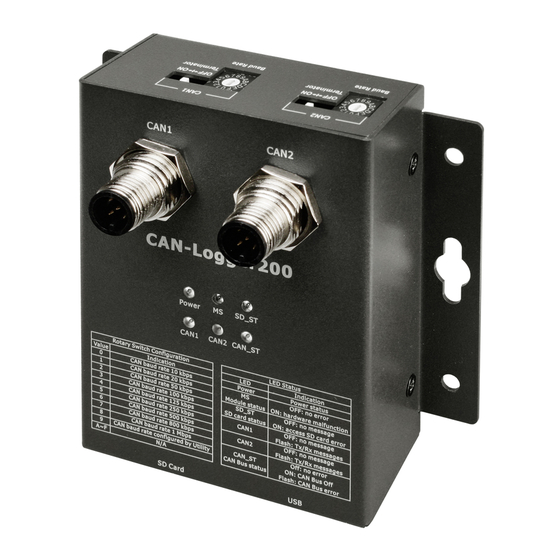
2.2. Appearance Figure 2-3 Appearance of CAN-Loger100 Figure 2-4 Appearance of CAN-Logger200 CAN-Logger series CAN Bus data logger devices User Manual (version 1.0.1) Page: 9 Copyright © 2015 ICP DAS Co., Ltd. All Rights Reserved. E-mail: service@icpdas.com... -
Page 10: Pin Assignment
2.3. Pin Assignment The pin assignments of 5-pin male M12 CAN connector of CAN-Logger series is shown in the following tables. Table 2-1 Pin Assignment Pin No Name Description F.G. Frame Ground. Voltage Source Input. +10V ~ +30V Power Ground. -
Page 11: Rotary Switch
2.4. Rotary Switch When users would like to update the module’s firmware or change the CAN baud rate of the CAN-Logger series, use the rotary switch on the top side to achieve this purpose. Figure 2-5 Location of CAN-Logger100/CAN-Logger200 Rotary Switch There are 16 sections on the rotary switch. -
Page 12: Led Indicator
2.5. LED Indicator There are 6 LEDs on the CAN-Logger series. One for power indication, one for hardware status indication, one for SD status indication and three for CAN Bus indication. The LED assignment and description are shown as follows. - Page 13 For CAN-Logger200: These LEDs of “Power”, “MS”, “SD_ST”, “CAN_ST”, “CAN2”, “CAN1” would flash in the clockwise direction. CAN-Logger series CAN Bus data logger devices User Manual (version 1.0.1) Page: 13 Copyright © 2015 ICP DAS Co., Ltd. All Rights Reserved. E-mail: service@icpdas.com...
-
Page 14: Terminator Resistor Setup
Figure 2.8 CAN Bus network topology Each CAN-Logger series includes one build-in 120Ω terminator resistor, users can decide if it is enabled or not. The DIP switch for terminator resistor is under the top side. Figure 2-9 Location of Terminator Resistor DIP Switch of CAN-Logger100 Figure 2-10 Location of Terminator Resistor DIP Switch of CAN-Logger200 CAN-Logger series CAN Bus data logger devices User Manual (version 1.0.1) - Page 15 Figure 2-12 Application 1 If your application is like the structure as follows, the terminator resistor is not needed. Figure 2-13 Application 1 CAN-Logger series CAN Bus data logger devices User Manual (version 1.0.1) Page: 15 Copyright © 2015 ICP DAS Co., Ltd. All Rights Reserved. E-mail: service@icpdas.com...
-
Page 16: Wire Connection
The wire connection of the CAN-Logger series is displayed below. Figure 2-42 Wire Connection for CAN-Logger series CAN-Logger series CAN Bus data logger devices User Manual (version 1.0.1) Page: 16 Copyright © 2015 ICP DAS Co., Ltd. All Rights Reserved. E-mail: service@icpdas.com... -
Page 17: Network Deployment
< 410 ~1.3 (AWG16) < 980 < 900 < 780 < 670 CAN-Logger series CAN Bus data logger devices User Manual (version 1.0.1) Page: 17 Copyright © 2015 ICP DAS Co., Ltd. All Rights Reserved. E-mail: service@icpdas.com... -
Page 18: Software Utility
4. Software Utility When users want to use user-defined CAN baud rate, CAN message filter and diagnostic function on the CAN-Logger series, the CAN-Logger Utility tool may be needed. 4.1. Install the CAN-Logger Utility Step 1: Get the CAN-Logger Utility... - Page 19 After installing the .Net Framework components, the software will continue to install the Utility tool. 1. Click the “Next” button to continue. 2. Select the installation path of the CAN-Logger Utility and click the “Next” button. CAN-Logger series CAN Bus data logger devices User Manual (version 1.0.1) Page: 19 ...
- Page 20 3. Confirm the installation. Click the “Next” button to start the installation 4. Installation complete. Click the “Close” button to exit CAN-Logger series CAN Bus data logger devices User Manual (version 1.0.1) Page: 20 Copyright © 2015 ICP DAS Co., Ltd. All Rights Reserved. E-mail: service@icpdas.com...
-
Page 21: Setting Up The Can-Logger Series
Users can find the communication cable (CA-USB15) in the product box. Figure 4-1 Wire connection of the USB Step 2: Execute theCAN-Logger Utility tool. CAN-Logger series CAN Bus data logger devices User Manual (version 1.0.1) Page: 21 Copyright © 2015 ICP DAS Co., Ltd. All Rights Reserved. E-mail: service@icpdas.com... -
Page 22: Start To Use Can-Logger Utility Tool
D CAN Bus status frame. After connecting with module, user can get the CAN Bus status information on this frame. CAN-Logger series CAN Bus data logger devices User Manual (version 1.0.1) Page: 22 ... -
Page 23: Configure The Can-Logger Series
Please refer to the following steps to configure the CAN-Logger series. Step1: Select the necessary CAN-Logger module and then press the “Configure” buttom. CAN-Logger series CAN Bus data logger devices User Manual (version 1.0.1) Page: 23 ... - Page 24 ‘1Mbps’. If you want to use user-defined CAN baud rate, user can set the ratary switch to ‘9’, and then set the “Defined Baud Rate” parameter to the CAN baud rate that you need. CAN-Logger series CAN Bus data logger devices User Manual (version 1.0.1) Page: 24 ...
- Page 25 “RTC Battery Voltage”: Crrent battery voltage that RTC used. The battery valtage must be the value between 2.2V to 3.6V CAN-Logger series CAN Bus data logger devices User Manual (version 1.0.1) Page: 25 Copyright © 2015 ICP DAS Co., Ltd. All Rights Reserved. E-mail: service@icpdas.com...
-
Page 26: Transmit Can Messages
The following steps listed how to used these two methods to send a CAN message. “Basic Mode” “Advanced Mode” Step 1: Connect with the selected CAN-Logger device. CAN-Logger series CAN Bus data logger devices User Manual (version 1.0.1) Page: 26 ... - Page 27 “Transmission number”: Number of CAN messages need to be sent when press “Transmit” button. “Period”: Period of sending a CAN message. CAN-Logger series CAN Bus data logger devices User Manual (version 1.0.1) Page: 27 Copyright © 2015 ICP DAS Co., Ltd. All Rights Reserved. E-mail: service@icpdas.com...
- Page 28 3. Enable the “Valid” parameter of the message that you want to transmit. 4. Press the “Send” button to start to send data to CAN Bus via CAN-Logger device. CAN-Logger series CAN Bus data logger devices User Manual (version 1.0.1) Page: 28 ...
-
Page 29: Receive Can Messages
CAN Bus will be shown on the “Receive frame”. The following picture is an example of data listed on the “Receive frame” and the detail information of each items on the “Receive frame” are shown below. CAN-Logger series CAN Bus data logger devices User Manual (version 1.0.1) Page: 29 ... - Page 30 Date time of the CAN-Logger device to transmit/receive/detect the message. “Timestamp”: Timestamp of the CAN-Logger device to transmit/receive/detect the message. The unit of this field is micro-second. CAN-Logger series CAN Bus data logger devices User Manual (version 1.0.1) Page: 30 ...
-
Page 31: Check Can Bus State
After connecting with the CAN-Logger device, the CAN Bus state of the device will be shown on the right-bottom of the main frame. The detail information of each items are shown below. CAN-Logger series CAN Bus data logger devices User Manual (version 1.0.1) Page: 31 ... - Page 32 The CAN controller is in busoff state. “Error Counter”: Transmit/Receve error counters. Name Description Transmit error counter Receve error counter CAN-Logger series CAN Bus data logger devices User Manual (version 1.0.1) Page: 32 Copyright © 2015 ICP DAS Co., Ltd. All Rights Reserved. E-mail: service@icpdas.com...
-
Page 33: Verify Data Saved In The Sd Card
“mm”=08: August [dd]: day of the month, value from 01 to 31. [nnn]: file number, value from 000 to 999. CAN-Logger series CAN Bus data logger devices User Manual (version 1.0.1) Page: 33 Copyright © 2015 ICP DAS Co., Ltd. All Rights Reserved. E-mail: service@icpdas.com... - Page 34 ‘ between the front side and back-end of the filter data. Example: Filter rule = [key string1] [operator] ‘[filter data1]’ [key word] [key string2] [operator] ‘[filter data2]’ CAN-Logger series CAN Bus data logger devices User Manual (version 1.0.1) Page: 34 ...
- Page 35 Display messages that data on “Fdata” field is match ’11 22 33 44 55 66 77 88’ Filter rule: Fdata = ‘11 22 33 44 55 66 77 88’ CAN-Logger series CAN Bus data logger devices User Manual (version 1.0.1) Page: 35 ...
-
Page 36: Format Sd Card
SDHC card. If user uses their own SDHC card, inorder to make the CAN-Logger series to have the best performance to read/write data from/to SDHC card, we suggest user to format the SDHC card to FAT32 with 32KB clusters before used. -
Page 37: Firmware Upgrade
(CA-USB15) in the product box. Figure 5-1 Rotary switch setting and wire connection of the USB CAN-Logger series CAN Bus data logger devices User Manual (version 1.0.1) Page: 37 Copyright © 2015 ICP DAS Co., Ltd. All Rights Reserved. E-mail: service@icpdas.com... - Page 38 Power, MS, SD_ST, CAN_ST, CAN2, CAN1 LEDs of the module will scroll to flash per 200 milliseconds and users can upgrade the firmware of the CAN-Logger series module via USB and the module will become a “USB Mass Storage Device” and also shows a folder like following picture automatically.
- Page 39 Step 6: Select USB port and the necessary USB Disk of PC. Step 7: Press the the “Browser…” button and select the firmware file (*.fw). CAN-Logger series CAN Bus data logger devices User Manual (version 1.0.1) Page: 39 Copyright © 2015 ICP DAS Co., Ltd. All Rights Reserved. E-mail: service@icpdas.com...
- Page 40 Step 9: Set the CAN1 baud rate of rotary switch to the necessary location. Step 10: Reboot the module and press the “Exit” button to exit. CAN-Logger series CAN Bus data logger devices User Manual (version 1.0.1) Page: 40 ...
-
Page 41: Dimension
6. Dimension Figure 6-1 Dimension of CAN-Logger100 CAN-Logger series CAN Bus data logger devices User Manual (version 1.0.1) Page: 41 Copyright © 2015 ICP DAS Co., Ltd. All Rights Reserved. E-mail: service@icpdas.com... - Page 42 Figure 6-2 Dimension of CAN-Logger200 CAN-Logger series CAN Bus data logger devices User Manual (version 1.0.1) Page: 42 Copyright © 2015 ICP DAS Co., Ltd. All Rights Reserved. E-mail: service@icpdas.com...
-
Page 43: Appendix
The CAN module is not in busoff state. The CAN controller is in busoff state. 31:8 Reserved CAN-Logger series CAN Bus data logger devices User Manual (version 1.0.1) Page: 43 Copyright © 2015 ICP DAS Co., Ltd. All Rights Reserved. E-mail: service@icpdas.com... -
Page 44: Can Error Counter Register
The receive counter has reached the error passive level as defined in the CAN2.0 specification. 31:16 Reserved CAN-Logger series CAN Bus data logger devices User Manual (version 1.0.1) Page: 44 Copyright © 2015 ICP DAS Co., Ltd. All Rights Reserved. E-mail: service@icpdas.com... -
Page 45: Emi Ferrite Split/Snap-On Core
7.3. EMI Ferrite Split/Snap-On Core CAN-Logger series CAN Bus data logger devices User Manual (version 1.0.1) Page: 45 Copyright © 2015 ICP DAS Co., Ltd. All Rights Reserved. E-mail: service@icpdas.com...
Need help?
Do you have a question about the CAN-Logger Series and is the answer not in the manual?
Questions and answers