Table of Contents
Advertisement
Quick Links
Warranty
All products manufactured by ICP DAS are under warranty regarding
defective materials for a period of one year, beginning from the date of
delivery to the original purchaser.
Warning
ICP DAS assumes no liability for any damage resulting from the use of
this product. ICP DAS reserves the right to change this manual at any
time without notice. The information furnished by ICP DAS is believed to
be accurate and reliable. However, no responsibility is assumed by ICP
DAS for its use, or for any infringements of patents or other rights of
third parties resulting from its use.
Copyright
Copyright © 2020 by ICP DAS. All rights are reserved.
Trademarks
Names are used for identification purposes only and may be registered
trademarks of their respective companies.
Technical Support
If you have any problems, feel free to contact us via email at
service@icpdas.com.
MDC-211-WF
User Manual
Advertisement
Table of Contents

Related Manuals for ICP DAS USA MDC-211-WF


Summary of Contents for ICP DAS USA MDC-211-WF
- Page 1 MDC-211-WF User Manual Warranty All products manufactured by ICP DAS are under warranty regarding defective materials for a period of one year, beginning from the date of delivery to the original purchaser. Warning ICP DAS assumes no liability for any damage resulting from the use of this product.
-
Page 2: Table Of Contents
1.3. Specifications ......................7 1.4. Size (Unit : mm) ......................8 1.5. Configuration Instructions ..................9 2. Getting Started With MDC-211-WF ...... 10 2.1. Preparation ......................11 2.2. Login MDC-211-WF Web Interface ..............14 2.3. Set Port Information ....................15 2.4. - Page 3 Q3 - How are the Internal Registers corresponding to the polled data in a MDC-211- WF? 38 Q4 - How to read each MDC-211-WF command status via the Modbus communication? Q5 - How to update the firmware? .................. 40 6. Appendix ..........43 6.1.
-
Page 4: Introduction
Wireless, RS-232 and RS-485 communication interfaces, can link the Modbus RTU devices to the Ethernet network. MDC-211-WF can read the data of Modbus RTU device according to the user-defined command table, and integrate the data of different Modbus RTU devices into the format of the continuous address so that the remote monitor host can connect to MDC-211-WF from Ethernet to access the data of multiple Modbus RTU devices at once. -
Page 5: Product Features
MDC-211-WF provides a simple, friendly Web interface (UI), users can login the MDC- 211-WF Web page via a Web Browser to set up and real-time detect the MDC-211-WF for the communication status and update frequency of each Modbus RTU command. - Page 6 Serial port communication parameters and the Modbus RTU commands that settings can also be edited in a *.csv file and import into the MDC-211-WF from the Web UI, and then start to monitor the data of the remote Modbus RTU devices.
- Page 7 The MDC-211-WF is a Modbus/RTU to Modbus/TCP gateway in Limit-AP mode. The device can connect to MDC-211-WF by Wi-Fi. The device can connect to the WF-2572M when it didn’t have Wi-Fi function. The device can send Modbus/TCP command to acquire data from Modbus/RTU device.
-
Page 8: Specifications
Power Consumption 5 W @ 24 V Environment Operating Temperature -25°C ~ +75°C Storage Temperature -30°C ~ +80°C Humidity 10~90% RH, Non-condensing ICP DAS, MDC-211-WF user manual , v1.1 Page 7 Copyright © 2020 by ICP DAS. All rights are reserved. -
Page 9: Size (Unit : Mm)
1.4. Size (Unit : mm) Top view Left view Post view Front view Bottom view Right view ICP DAS, MDC-211-WF user manual , v1.1 Page 8 Copyright © 2020 by ICP DAS. All rights are reserved. -
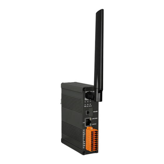
Page 10: Configuration Instructions
Antenna LED Indicator MicroSD Card Ethernet Port The MDC-211-WF is equipped with a RJ45 port for Ethernet LAN connection. When 100BASE‐TX is operating, the 10/100M LED is lit orange. When 10BASE‐T is operating or the machine is not connected to the network, it is turned off. When an Ethernet link is detected and an Ethernet packet is received, the Link/Act LED is lit green. -
Page 11: Getting Started With Mdc-211-Wf
Modbus Slave function for the Modbus data concentrator. ◆ MDC-211-WF Setting Flowchart •Hardware wiring •Set the MDC-211-WF and PC to the same local area network. (The default IP address of Preparation MDC-211-WF is 192.168.255.1) •Launch the browser and enter the IP address of MDC-211-WF •login MDC-211-WF (Both the default account and password are "Admin") -
Page 12: Preparation
Please follow Figure 2.1 wiring diagram, to wire the following items: 1. Power Supply : +10 VDC ~ +30 VDC 2. RS-485:D+ & D- 3. RS-232:TxD / RxD / GND 4. Ethernet:Connect the MDC-211-WF and computer into the same LAN through cable or Ethernet Switch/Hub. RS-485 INIT... - Page 13 Before connecting the MDC-211-WF, please set the MDC-211-WF to be the same LAN as the PC. Tables 2.1 shows the default network setting of MDC-211-WF. If it is in the different network area, please adjust network settings by the following software.
- Page 14 Figure. 2.3 Network parameter setting interface Step 4 Finally, click "Search Server" button again to find the MDC-211-WF module, to confirm that the network settings has been modified successfully. ICP DAS, MDC-211-WF user manual , v1.1 Page 13 Copyright © 2020 by ICP DAS. All rights are reserved.
-
Page 15: Login Mdc-211-Wf Web Interface
Login MDC-211-WF Web Interface This section describes how to login the MDC-211-WF Web interface. Step1 Once the PC and MDC-211-WF are in the same LAN, user can login the MDC-211-WF by entering the IP address on Web browser (IE11/Chrome/Firefox, resolution 800 x 600 or more is recommended), the login screen is shown as Figure 2.4:... -
Page 16: Set Port Information
2.3. Set Port Information MDC-211-WF provides one port Wi-Fi, one port Ethernet, one port RS-232 and one port RS-485 communication interface, this section introduces the configuration procedure for these communication interface. ◆ Wi-Fi Port Setting Click "Module Setting" → "Wi-Fi", to read the current Wi-Fi setting parameters, if user want to adjust the Wi-Fi settings, click the "Modify"... - Page 17 "Cancel" button to discard the configuration and return to the previous page. NOTE - The new Ethernet settings only take effect after restarting the power of the MDC- 211-WF. ICP DAS, MDC-211-WF user manual , v1.1 Page 16 Copyright © 2020 by ICP DAS. All rights are reserved.
- Page 18 NOTE - The new Serial Port settings will take effect immediately after configuration without restarting the power of the MDC-211-WF. ICP DAS, MDC-211-WF user manual , v1.1 Page 17 Copyright © 2020 by ICP DAS. All rights are reserved.
-
Page 19: Set Mdc-211-Wf As Modbus Master
2.4. Set MDC-211-WF as Modbus Master Each Wi-Fi/RS-232/RS-485 communication interface on MDC-211-WF can be either set as Modbus Master or Modbus Slave. This section describes how to set the communication interface as the Modbus Master, and add the Modbus RTU devices to be monitored. - Page 20 "Cancel" go back to the previous page. If you want to remove the Modbus register, click the icon " ". ICP DAS, MDC-211-WF user manual , v1.1 Page 19 Copyright © 2020 by ICP DAS. All rights are reserved.
-
Page 21: Set Mdc-211-Wf As Modbus Slave
2.5. Set MDC-211-WF as Modbus Slave One of the MDC-211-WF Wi-Fi/RS-232/RS-485 ports can be set as Modbus Master or Modbus Slave (Ethernet port can only be used as Modbus Slave). This section describes how to set the communication interface as Modbus Slave. -
Page 22: Check Modbus Rtu Device Communication Status
MDC-211-WF Web interface. This section describes how to check the Modbus command status, real-time monitor the I/O channel status of Modbus RTU device, and inquire the relationship for the Modbus RTU device I/O and the MDC-211-WF Internal Register address. 2.6.1. Check polling status of Modbus command Click "I/O Information"... - Page 23 (3) If the "Status" item displays TIMEOUT, means the command was timeout and the device did not respond, please check the module wiring, and the following Modbus RTU device settings those need to be consistent with the settings in MDC-211-WF. Baud Rate...
-
Page 24: Inquire Corresponding Modbus Register Address
Figure 2.13. The "Remote" item in the mapping table represents the Register address of the Modbus RTU device; the "MDC-211-WF" item represents the corresponding Internal Register address. The users can access Internal Register address in the “MDC-211-WF" item via the Modbus protocol to control the entity Modbus RTU device. -
Page 25: Testing I/O Channel Status Of Modbus Rtu Device
2.6.3. Testing I/O Channel Status of Modbus RTU Device MDC-211-WF can real-time control the I/O channel of Modbus RTU devices via the standard Modbus protocol, and also provide Web UI to real-time control the Modbus I/O channel status. As Figure 2.14, users only need to click "I/O Information" and select the Modbus RTU device want to control, the Web UI will display the pre-set Modbus command and real-time display that Modbus device I/O channel status. -
Page 26: Export And Import The System Settings
3. Export and Import the System Settings The user can set up MDC-211-WF via the Web UI, and also can export the configuration to a *.csv file in the local computer for backup. More, the user can directly edit the setting parameters in a *.csv file and import the *.csv file into the MDC-211-WF module to complete... - Page 27 ◆ Import As Figure 3.2, click "Module Setting" → "Import/Export" → "Choose file" → "Import", then the *.csv file can be uploaded into MDC-211-WF and set up immediately. Figure 3.2 Module Setting Import page ICP DAS, MDC-211-WF user manual , v1.1 Page 26 Copyright ©...
-
Page 28: Format Descriptions For The Configuration File (*.Csv)
3.2. Format Descriptions for the Configuration File (*.csv) If the user wants to set up MDC-211-WF through the *.csv configuration file, the user can export a *.csv file from the Web Interface as the configuration template. For the detail steps, please refer to "3.1 Export and Import the Configurations ". - Page 29 Encryption 5: WEP Infrastructure mode 1: OPEN 2: WPA/WPA2 5: WEP Password Password The maximum length of password is 63 words ICP DAS, MDC-211-WF user manual , v1.1 Page 28 Copyright © 2020 by ICP DAS. All rights are reserved.
- Page 30 ◆ Ethernet Communication Settings The second part is for Ethernet settings. Ethernet label name and setting descriptions please see table 3.3 below. ICP DAS, MDC-211-WF user manual , v1.1 Page 29 Copyright © 2020 by ICP DAS. All rights are reserved.
- Page 31 0 (Disable) / 1 (Enable) NOTE – The IP, Mask and Gateway should be set up according to the local network. ICP DAS, MDC-211-WF user manual , v1.1 Page 30 Copyright © 2020 by ICP DAS. All rights are reserved.
- Page 32 0 (None) / 1 (Odd) / 2 (Even) / 3 (Mark) / 4 (Space) StopBit 0 / 1 / 2 Inter-character CharTime 1.5 ~ 10 (Unit: Character Time) Timeout ICP DAS, MDC-211-WF user manual , v1.1 Page 31 Copyright © 2020 by ICP DAS. All rights are reserved.
- Page 33 Ethernet fixed to Modbus Slave, no need to set Modbus Retry Retry 0 ~ 9 Modbus Timeout Timeout 0 ~ 65535 Polling Interval Interval 0 ~ 65535 ICP DAS, MDC-211-WF user manual , v1.1 Page 32 Copyright © 2020 by ICP DAS. All rights are reserved.
- Page 34 "#": means the system-defined label; do not change the name and location (order). "*": means the data that the user enabled. "-": means the data that the user does not enable. ICP DAS, MDC-211-WF user manual , v1.1 Page 33 Copyright © 2020 by ICP DAS. All rights are reserved.
-
Page 35: Parameter Descriptions
Wireless Channel Limit-AP The channel of Wi-Fi AP The application of Wi-Fi AP and Infrastructure mode can refer to page 6. ICP DAS, MDC-211-WF user manual , v1.1 Page 34 Copyright © 2020 by ICP DAS. All rights are reserved. -
Page 36: Serial Port Communication Interface
◆ Set Example Table 4.4 shows a setting example to set the RS-485 of MDC-211-WF as a Modbus Master, and the recommend parameter values for the Serial port. Table 4.4 MDC-211-WF and M-7000/PLC setting example... -
Page 37: Modbus Protocol Parameter Descriptions
4.2. Modbus Protocol Parameter Descriptions MDC-211-WF is a Modbus data concentrator with Wi-Fi / RS-232 / RS-485 / Ethernet interfaces. The users need to set a communication interface to Modbus Master / Modbus Slave (The interface not used can be set to “Disabled”). The following sections describe the parameters for setting to Modbus Master and Modbus Slave. -
Page 38: Modbus Slave Setting Parameters
◆ Example Table 4.6 below is a setting example to set MDC-211-WF to Modbus Master, and the recommend parameters. Table 4.6 MDC-211-WF and M-7000 or PLC communication setting example Project Wi-Fi RS-485 RS-232 Modbus Timeout Modbus Retry Polling Interval 4.2.2. Modbus Slave Setting Parameters ◆... -
Page 39: Faq
Q1 - What are the maximum numbers of polling definition and Internal Register in a MDC-211-WF? The maximum number of polling definition in a MDC-211-WF is 240 commands, each definition can access up to 64 Internal Registers. Each of the four tables (DI/DO/AI/DO) can store up to 9600 Internal Registers for polled data. - Page 40 0: Indicates that the connection is in normal status. 0xFFFF: Connection Timeout 0xFF00: Command not enabled (Disabled) 0x8XYY: Communication error. X-function code, YY– Error code, as Table 5.3 below ICP DAS, MDC-211-WF user manual , v1.1 Page 39 Copyright © 2020 by ICP DAS. All rights are reserved.
-
Page 41: Q5 - How To Update The Firmware
Update Tool: http://ftp.icpdas.com/pub/cd/usbcd/napdos/wifi/mdc-211-wf/tools/ (2) Short the FW with P.GND of MDC-211-WF and turn on the power. When the six LEDs of MDC-211-WF turn blinking alternately, the MDC-211-WF is successfully entered the firmware updating mode. ICP DAS, MDC-211-WF user manual , v1.1 Page 40 Copyright ©... - Page 42 (3) Execute “FW_Update_Tool.exe” with the administrator privileges ( ) and follow the steps as Figure 5.3: In "Download Interface", select a network port for connecting to MDC-211-WF. In "Firmware Path", select the latest firmware update file (MDC211WF_xxxx.fw). In "Firmware Update", click “Update” to start the firmware updating.
- Page 43 Figure 5.3 FW_Update_Tool firmware update steps ICP DAS, MDC-211-WF user manual , v1.1 Page 42 Copyright © 2020 by ICP DAS. All rights are reserved.
-
Page 44: Appendix
Blinking (500 ms) There are Modbus command polling errors Steady Unlit No errors DATA Blinking (500 ms) Receive data from Wi-Fi ICP DAS, MDC-211-WF user manual , v1.1 Page 43 Copyright © 2020 by ICP DAS. All rights are reserved. - Page 45 【Other】If the above six LEDs are blinking alternately, the module is into the firmware update mode (bootloader), which can update the firmware with the "FW_Update_Tool". For more information please refer to the FAQ - Q6. ICP DAS, MDC-211-WF user manual , v1.1 Page 44 Copyright © 2020 by ICP DAS. All rights are reserved.
Need help?
Do you have a question about the MDC-211-WF and is the answer not in the manual?
Questions and answers