Subscribe to Our Youtube Channel
Summary of Contents for Trikdis FireCom
- Page 1 User M anual a nd I nstallation G uide Draugystes g . 1 7, LT-‐51229 K aunas E-‐mail: i nfo@trikdis.lt www.trikdis.lt ...
-
Page 2: Table Of Contents
o f l ow v oltage a nd s ignal t ransmission d evices a nd t heir s afety r equirements. Communicator FireCom must be set up in a limited access area and in a safe distance from sensitive electronic ... -
Page 3: Gsm C Ommunicator F Irecom
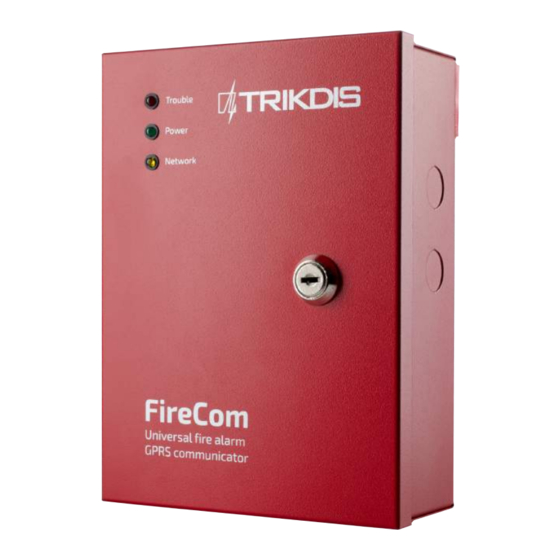
Operation d escription Communicator FireCom is connected to UniPOS fire security control panel serial output port. Communicator receives s erial p ort s ignals a nd g enerates c orresponding C ontact I D m essages. ... -
Page 4: Equipment
1.2. Technical p arameters GSM m odem f requencies 850 / 9 00 / 1 800 / 1 900 M Hz TCP/IP o r U DP/IP v ia G PRS GSM ... -
Page 5: Construction
1.5. Construction Electronic elements of the communicator are mounted in the printed circuit boards which are situated in the metal c ase. T hree c ommunication a nd o peration l ight i ndicators a re l ocated i n t he e xternal i ndication b oard ( 1). P ower supply unit, processor, GSM modem, GSM antenna connector (3), SIM card slot (4), internal light indicators (5), USB ... -
Page 6: Communicator I Nstallation
VL1 Processor i n o peration, n o f ailures, denotes o peration o f t he Flashes p eriodically In o ther c ases, -‐ o peration f ailures i r m alfunction. microprocessor ... -
Page 7: Setting O Peration P Arameters
USB_COM.inf f rom t he w ebsite ww.trikdis.lt. A U SB d river i nstallation w indow F ound N ew H ardware W izard s hould ... - Page 8 the l ist P ort. Note: the particular USB port to which the communicator is connected a ppears o nly w hen t he t wo a re c onnected. ...
- Page 9 Object I D Field t o e nter t he f our-‐digit i dentification n umber; Hex Tick i f h exadecimal n umbers w ill b e u sed f or e ntering t he o bject I D; SIM ...
- Page 10 Primary r eporting Select the main connection channel via which communicator will send messages to the monitoring p anel: Tick GPRS and enter the IP address and the port number of the monitoring panel in the fields Server ...
- Page 11 Recommended Event „E“ e vent d escription „R“ e vent d escription CID c ode Internal clock of the Internal clock of the ...
- Page 12 Telephone Enter user phone numbers T1, T2, T3, T4 to which SMS messages will be sent. Phone numbers are e ntered w ith t he i nternational c ountry c ode, b ut w ithout t he + s ign; Name ...
-
Page 13: Upgrading C Ommunication F Irmware
Send an SMS message to the GSM number of the SIM card inserted into the communicator FireCom in order to ... - Page 14 Send an SMS message to the GSM number of the SIM card inserted into communicator FireCom (for details see ...
-
Page 15: Warranty A Nd L Imitation O F L Iability
TRIKDIS r eserves t he r ight t o e dit, a dd a nd/or c hange t he i nformation i n t he m anual. ... -
Page 16: Annex 1 . C Ommunicator F Irecom C Onnection D Iagrams
7. Annex 1 . C ommunicator F ireCom c onnection d iagrams 7.1. Diagram f or c onnecting t o U niPOS f ire c ontrol p anels F S5100 a nd F S5200 ... - Page 17 7.2. Diagram f or c onnecting t o U niPOS f ire c ontrol p anel I FS 7 002 2 RXD 3 TXD 4 ...
- Page 18 7.3. Diagram f or c onnecting t o r elay o utputs o f f ire c ontrol p anels Input type EOL, resistance at the end of the line (EOL = 10kΩ) ...
- Page 19 8. Annex 2. Communicator FireCom fire control panel messages for the monitoring station Messages g enerated b y c ontrol p anel I FS 7 002 ( as i n c ontrol p anel d escription) a nd c orresponding C ontact I D c odes: ...
- Page 20 Manual S et E 627 00 000 Remote S et E 627 00 000 Deact. I nput ...
- Page 21 Messages g enerated b y c ontrol p anel F S 5 100 ( as i n c ontrol p anel d escription) a nd c orresponding C ontact I D c odes: ...
-
Page 22: Annex 3 . C Ommunicator F Irecom M Essages F Or T He U Sers
9. Annex 3 . C ommunicator F ireCom m essages f or t he u sers Notes: Communicator F ireCom m ay s end t he s ame m essages a s t hose d esigned f or c ommunicator G 10. S ome e vent codes ... -
Page 23: Annex 4 . S Cheme O F C Ommunicator F Irecom M Ounting H Oles
10. Annex 4 . S cheme o f c ommunicator F ireCom m ounting h oles 23 ...


Need help?
Do you have a question about the FireCom and is the answer not in the manual?
Questions and answers