Table of Contents
Advertisement
INSTALLATION AND OWNER GUIDE
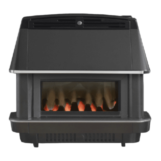
Model 474 Valentia
Balanced Flue
ROOM SEALED RADIANT / CONVECTOR
GAS FIRE
We trust that this guide gives
sufficient details to enable this
appliance to be installed, operated
and maintained satisfactorily.
However, if further information is
required, our Valor Technical
Helpline will be pleased to help.
Telephone 0844 879 35 88
(National call rates apply in the
United Kingdom).
In the Republic of Ireland Telephone
01 842 8222.
INSTALLER: Please leave this guide with the owner
©
GDC Group Ltd. 2014
08/52395/0
Advertisement
Chapters
Table of Contents

Related Manuals for Valor 474 Valentia


Summary of Contents for Valor 474 Valentia
- Page 1 08/52395/0 INSTALLATION AND OWNER GUIDE Model 474 Valentia Balanced Flue ROOM SEALED RADIANT / CONVECTOR GAS FIRE We trust that this guide gives sufficient details to enable this appliance to be installed, operated and maintained satisfactorily. However, if further information is required, our Valor Technical Helpline will be pleased to help.
- Page 2 THIS APPLIANCE IS FOR USE WITH NATURAL GAS (G20). UNDER NO CIRCUMSTANCES IS THIS APPLIANCE TO BE CONVERTED TO LPG. AN LPG CONVERSION KIT DOES NOT EXIST FOR THIS APPLIANCE THIS APPLIANCE IS SUITABLE ONLY FOR INSTALLATION IN THE UNITED KINGDOM (GB) AND THE REPUBLIC OF IRELAND (IE).
- Page 3 BS EN ISO 9001 quality system accepted by the British Standards Institute. The Highest Standards Valor Fires is a member of SBGI and HHIC (Heating and Hot water Industry Council) that work to ensure high standards of safety, quality and performance. Careful Installation...
-
Page 4: Installer Guide
INSTALLER GUIDE INSTALLER GUIDE FOR OWNER GUIDE SEE PAGES 24 TO 35 © GDC Group Ltd. 2014 Page 4... -
Page 5: Table Of Contents
INSTALLER GUIDE CONTENTS Section Heading Page INSTALLER GUIDE 4 - 22 OWNER GUIDE 24 - 35 1. SAFETY 2. ACCESSORY LIST 3. APPLIANCE DATA AND EFFICIENCY 3.1 General information. 3.2 Efficiency. 4. GENERAL INSTALLATION REQUIREMENTS 4.1 Regulations, Standards and Law. 4.2 Siting General. - Page 6 INSTALLER GUIDE CONTENTS (Continued) Section Heading Page 9. SERVICING 9.1 Remove Outer Case 9.2 Gas Tap Assembly 9.3 Burner Assembly 9.4 Main Burner Injectors 9.5 Pilot Injector (SIT No. 34) 9.6 Pilot Filter 9.7 Thermocouple 9.8 Spark Electrode 9.9 Pilot Burner 10.
-
Page 7: Safety
INSTALLER GUIDE 1. SAFETY Installer The fire can be wall or hearth mounted on a non-combustible wall or hearth, and can be fitted into a suitable fire surround. It can be installed from the inside of a building making it ideal for rooms where access from the outside is difficult, for example multi- storey buildings. -
Page 8: Accessory List
INSTALLER GUIDE 2. ACCESSORY LIST Note that in England and Wales the Building Regulations require a terminal guard to be fitted if the terminal is less than 2m (6ft 6in) from the level of any ground, balcony, flat roof or place to which any person has access and which adjoins the wall in which the outlet is situated. -
Page 9: Efficiency
INSTALLER GUIDE 3.2 Efficiency. The efficiency of this appliance has been measured as specified in BS EN 613 and the result is as below: Model Efficiency % (Gross) 79.3 The gross calorific value of the fuel has been used for this efficiency calculation. The test data from which it has been calculated has been certified by Advantica Certification services (0087). -
Page 10: Siting General
INSTALLER GUIDE In Northern Ireland, the current edition of the Building regulations (Northern Ireland) issued by the Department of the Environment for Northern Ireland. In the Republic of Ireland the installation must be carried out by a competent person and also conform to the relevant parts of: a) The current edition of IS 813 “Domestic Gas Installations”... -
Page 11: Fireplace Clearances
INSTALLER GUIDE 4.3 Fireplace clearances (See Fig. 2). 4.3.1 The minimum height from the extreme top surface of the fire to the underside of any shelf made from wood or other combustible materials is as follows: For a shelf up to 150mm deep Minimum height from the extreme top surface of the fire = 150mm. - Page 12 INSTALLER GUIDE Minimum Terminal position distance. Directly below an opening, air brick, opening window etc. 300mm Above an opening, air brick, opening window etc. 300mm Horizontally to an opening, air brick, opening window etc. 300mm Below gutters, soil pipes or drain pipes. 300mm Below eaves.
- Page 13 INSTALLER GUIDE Fig. 4 © GDC Group Ltd. 2014 Page 13...
-
Page 14: Pack Contents
INSTALLER GUIDE 5. PACK CONTENTS The fire is packed in a carton together with the following items (Ref Fig. 5):- Medium flue assembly and sealing tape (two pieces). Gasket pack comprising flue and air duct gaskets and sealing gasket. Flue sealing plate. Pack of fittings comprising: 4 x Wall fixing screws (2in wood) 810500... -
Page 15: Preparation Of Wall
INSTALLER GUIDE 6. PREPARATION OF WALL NOTE: The following instructions relate to normal brick walls. If the wall is wholly or partly of combustible material, a combustible wall kit (optional extra) must be used. Check the wall thickness. Three different sizes of flue available for wall thickness up to 508mm as shown below. -
Page 16: Combustible Walls
INSTALLER GUIDE COMBUSTIBLE WALLS For installation on walls constructed or comprising combustible materials, reference should be made to the requirements of BS 5440 and the Building Regulations. Timber Framed Housing: For a timber framed house, the fire can be installed as directed in The Institute of Gas Engineers Utilization Procedure IGE/UP/7 GAS INSTALLATIONS IN TIMBER FRAME BUILDINGS. -
Page 17: Preparation Of Fire
INSTALLER GUIDE † Note:It is not necessary to allow for shrinkage of timber frames in existing buildings where the necessary length of time has elapsed to allow for any contraction of the timber frame. 7. PREPARATION OF FIRE Remove Outer Case Remove the door mask by first lifting upwards to clear the retaining pins and then swinging it out from the fire bottom first. -
Page 18: Connect Gas Supply
INSTALLER GUIDE NOTE: The flue and air ducts do not need cutting unless the short flue assembly is being fitted. In this case measure the wall thickness. Then subtract this length from 203mm to give the length ‘B’ shown in Fig. 4B. Cut this length from the plain ends of both the inner flue and the inner air ducts. -
Page 19: Commisioning
INSTALLER GUIDE 8. COMMISSIONING Check the Gas Pressure and F.S.D. Operation Remove the pressure test point sealing screw located on the gas tap and connect a pressure gauge to the test point. Temporarily fit the control knob. Light the fire. Please refer to the Users Instructions. Turn the control knob to the full on position marked HIGH. - Page 20 INSTALLER GUIDE 9. SERVICING Important Notes: TURN OFF THE GAS SUPPLY BEFORE COMMENCING ANY SERVICING, ALWAYS TEST FOR GAS SOUNDNESS AFTER SERVICING OR EXCHANGING ANY COMPONENT. It is recommended that the appliance is serviced at least once a year. 9.1. REMOVE OUTER CASE Remove the decorative rail from the finials.
- Page 21 INSTALLER GUIDE NOTE: If the fire had been previously installed in a fire surround with a restricted access on the right side then it will be necessary to remove the fire from the wall to remove the burner assembly as previously detailed. Alternatively it is possible under these circumstances to remove the control/pipework assembly from the burner first and to withdraw the burner through the front firebox opening.
- Page 22 INSTALLER GUIDE 10. SHORT LIST OF PARTS PART NUMBER DESCRIPTION 991979 Coal Bed 991725 Control Knob 987623 Gas Tap c/w switch 820363 Spark Electrode 822131 Pilot Filter 822205 Thermocouple 991635 Door Assembly 987632 Ignition Lead 987633 Lead - switch/spark generator (2 off) ©...
- Page 23 INSTALLER GUIDE © GDC Group Ltd. 2014 Page 23...
-
Page 24: Owner Guide
OWNER GUIDE OWNER GUIDE FOR WARRANTY AND SERVICE INFORMATION SEE PAGES 32 TO 35 © GDC Group Ltd. 2014 Page 24... - Page 25 OWNER GUIDE CONTENTS Section Heading Page SAFETY GAS CONSUMPTION OPERATING THE FIRE To light the fire To turn off Heat Settings TO REMOVE THE GLASS DOOR CLEANING YOUR FIRE Coal Bed Cleaning the ceramic fuel effect pieces. SERVICING AND MAINTENANCE Regular maintenance WARRANTY AND SERVICE This gas fire is designed to meet the most stringent quality, performance and safety...
-
Page 26: Safety
OWNER GUIDE SAFETY IF YOU SMELL GAS - DON’T SMOKE. - EXTINGUISH ALL NAKED FLAMES. - DON’T TURN ELECTRICAL SWITCHES ON OR OFF. - TURN OFF THE GAS SUPPLY AT THE METER. - OPEN DOORS AND WINDOWS TO GET RID OF THE GAS. - IMMEDIATELY CALL THE GAS EMERGENCY SERVICE FROM A NEIGHBOURS PHONE - SEE YOUR LOCAL TELEPHONE DIRECTORY. - Page 27 OWNER GUIDE Do provide the following clearance for combustible projections up to a depth of 178mm (Measured from the rear fixing plane of the fire). A minimum clearance of 75mm should be maintained at the left and right side of the fire. This is measured from the extreme side of the fascia.
-
Page 28: Gas Consumption
OWNER GUIDE Please Note As with all windows, the glass may need to be cleaned both outside and inside from time to time. The window and frame on this appliance has, therefore been designed to be customer removable allowing you to clean it without having to call in a service engineer. -
Page 29: Heat Settings
OWNER GUIDE Turn the control knob to setting 1 before choosing any other. NOTE: The control knob should be pushed in slightly before turning, and always set to one of the stated positions. It is connected to the gas tap by a universal coupling and will have a ‘loose feel’ to it, which should not cause concern.warms up, as explained above, then release it. -
Page 30: Cleaning Your Fire
OWNER GUIDE CLEANING YOUR FIRE (SEE COAL BED) NOTE: Abrasive cleaners should never be used. All cleaning should be carried out when the fire is cold. As the fire is used, the bright metal finish around the fuel bed will darken to enhance the fuel effect. There is no need to use metal polish on these parts as the discoloration is normal. -
Page 31: Cleaning The Ceramic Fuel Effect Pieces
OWNER GUIDE NOTE: Cleaning ceramic fuel effect pieces. This product uses fuel effect pieces and gaskets containing Refractory Ceramic Fibres (RCF), which are man-made vitreous silicate fibres. Excessive exposure to these materials may cause irritation to eyes, skin and respiratory tract. Consequently, it is important to take care when handling these articles to ensure that the release of dust is kept to a minimum. -
Page 32: Warranty And Service
OWNER GUIDE WARRANTY AND SERVICE Standard Warranty Terms & Conditions The warranty is for 12 months subject to contract. In the United Kingdom servicing can be carried out either by a GDC service operative or a GAS SAFE REGISTER operative. You must register your fire by calling our telephone registration line on 0800 597 8500. - Page 33 OWNER GUIDE What you need to do if you experience a problem with the operation of the fire: You should always contact your installer first, because the cause of the fault may not be related to the fire. If your installer confirms that the fault is with the fire and they can’t repair it, our friendly customer service team is on hand to help.
- Page 34 OWNER GUIDE To be completed by installer: Installer Details (Block Capitals) Installer Name Gas Safe Register or Corgi Registration Number. Company Name. Company Address Company Telephone number Company Fax number © GDC Group Ltd. 2014 Page 34...
-
Page 35: Owner Guide
Fascia code - Can be found close to the information label (Block Capitals) A LABEL CONTAINING THE FASCIA CODE MAY HAVE BEEN PLACED INSIDE THIS BOX. Brand (Please tick) Valor Other......Date of Installation © GDC Group Ltd. 2014 Page 35... - Page 36 © GDC Group Ltd. 2014 Page 36...
- Page 37 © GDC Group Ltd. 2014 Page 37...
Need help?
Do you have a question about the 474 Valentia and is the answer not in the manual?
Questions and answers