Table of Contents
Advertisement
Advertisement
Table of Contents

Subscribe to Our Youtube Channel
Related Manuals for Octave Phono Module


Summary of Contents for Octave Phono Module
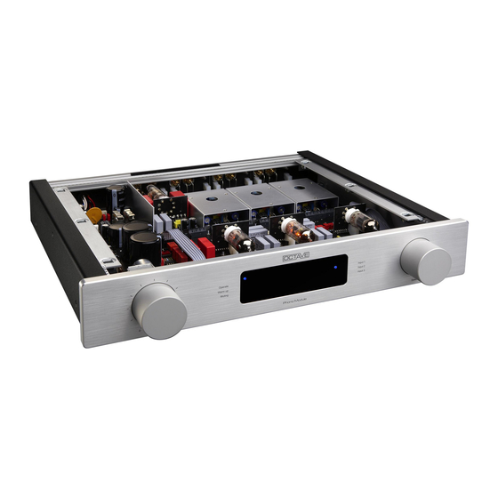
- Page 1 PHONO MODULE...
- Page 2 We have specialized in tube amplification for the past 25 years, during which time we have developed a number of innovative technologies that have earned us a reputation as one of the leaders in the field. We hope you will enjoy many hours of wonderful music with your OCTAVE preampli- fier. Andreas Hofmann...
-
Page 4: Table Of Contents
CONTENTS Page Introduction OCTAVE technology ..............1.1. Differences to other tube amps ............ 1.2. Phono Module Description ............Safety instructions ................ 2.1. Before you begin ................2.2. Placement ..................2.3. Warranty ..................Setting up ..................3.1. Connecting the amplifier ............... -
Page 5: Octave Technology
1.1. Characteristics of the OCTAVE tube technology Sound 1. The design goal of OCTAVE amplifiers is honest, natural sound repro- duction. The sound characteristics of an amplifier are derived from the sum of all its parts. Tubes themselves do not guarantee high quality sound. -
Page 6: Phono Module Description
RCA outputs. These RCA outputs can be used in the traditional manner for monitoring the signal or as a source for recording equipment. The Octave Phono Module is a four stage system comprising the Input Module, the RIAA Equaliza- tion, the Subsonic Filter and the Output Module. The Subsonic Filter can be bypassed. The power supply is external, and mounted in a magnetically-shielded housing. -
Page 7: Safety Instructions
Fuses should also only be changed by a qualified technician. Always replace fuses with ones of the same type and rating. If your amplifier requires servicing, please ship or take your equipment directly to OCTAVE or to one of our author- ized service centers. -
Page 8: Placement
2.2. Placement 1. Location OCTAVE equipment is designed strictly for use in a dry domestic environment. Do not use it in the open air or in damp environments! Never place plants or liquid filled containers on your OCTAVE equipment. Take care that objects do not fall or liquids are not spilled into the enclosure. -
Page 9: Setting Up
7. Switch on the other components in any sequence. 3.2. Running in All OCTAVE equipment is subject to a 48-hour continous run-in period at the factory to break in the unit. The tubes are individually selected for use in each particular model. -
Page 10: Main Unit
4. MAIN UNIT 4.1. Front View Level regulator, volume control With the volume control, you can regulate the level of the variable output (see chapter 6). LED status display Operate: indicates that the unit is switched on. Warm Up: (yellow LED) indicates that the unit is in the warm up phase. -
Page 11: Top View
4. MAIN UNIT 4.2. Top View Sliding switch for the Subsonic Filter In delivery state where the Filter is on (see Chapter. 4.6.). Flat Wire Connector Additional connections for the Line Input Module IN 4 (see Chapter. 5.4). You can connect one or two IN 4 Modules (maximum 2 pc) ... -
Page 12: Back View
4. MAIN UNIT 4.3. Rear View PSU Booster (Power Supply Unit Booster) Connector for the optional external power supply enhancement module. Power Supply Connector Connector for the external power supply. 4.4. Installing the Modules Placement of the Modules: ... -
Page 13: Power Supply
4. MAIN UNIT 4.5. External Power Supply Power Supply front Mains power switch, I = On Control LED Power Supply rear panel Mains Input, IEC receptacle Serial Number and Mains Voltage Connecting Cable with Plug Connector... -
Page 14: Tube Layout, Replacing Tubes
4. MAIN UNIT 4.6. Tube layout, Replacing tubes Tube Layout: ECC88 ECC81 ECC83 Tube (ECC83, 12AX7) is the Input Tube. Please use Low Noise Tubes of high quality with matched systems. Tube (ECC81, 12AT7) is for the Main Amplification Stage. Tube (ECC88, 6922, 6N23, 6N1,) is for the Output Buffer. -
Page 15: Subsonicfilter
4. MAIN UNIT 4.7. Subsonicfilter Subsonic Filter Uneven records and mismatched cartridge – tonearm combinations can result in low frequency signals in the range below 15Hz (addi- tional to the music reproduction). Signals of this low frequency cause excessive swing of the bass driver membrane, especially if slide switch it’s a bass-rexlex system. -
Page 16: Remote Control (Optional)
4. MAIN UNIT 4.7. Subsonic Filter Frequency Response of the Phono Module ( RIAA Curve ) with and without Subsonic Filter: Flat Graph, Fre- quency Response without Subsonic Filter Descending Graph, Frequency Response with Subsonic Filter Low Frequency Signals below 20Hz will be reduced through the Subsonic Filter by 12dB / Octave. -
Page 17: Technical Data, Main Unit
Crosstalk, Module to Module > 100 dB Subsonic Filter Cut Off Frequency 15 Hz / - 3 dB / 12 dB / Octave Tolerance RIAA-Equalization The Equalization follows the RIAA Curve within the Tolerance of 0.2 dB in the frequency range of 10Hz to 50kHz. - Page 18 The graph below depicts three different stray fields. First ( 1 ) the stray field of a room without transformer, the stay field of the shielded transformer of the Octave Phono Module ( 2 ), and the stray field of a conventional transformer ( 3 ). It is easy to see that the stray field extends to the midrange (with peaks up to 2 kHz).
-
Page 19: In 1: Mm Rca
5. INPUTS 5.1. Input IN 1: MM RCA Rear View 2 Mounting Size M3 x 8 cross slot, Screws Phillips Nr 1 screwdriver Input Right - Left and Tonearm- Ground Connecting Connection (GND) Field Right Channel: red; Left Channel: white 2 Mounting see above Screws... - Page 20 5. INPUTS 5.1. Input IN 1: MM RCA Specifications Sensitivity 3 - 5 mV Input Impedance 1 kOhm / 47 kOhm / 220 pF Gain Factor 38 dB Signal to Noise Ratio - 94 dB / 1 kHz Bandpass Measurement Static Noise Level MM-Input Reading on the FIX Output THD + Noise in the Range of 400 Hz - 20 kHz...
-
Page 21: In 2: Mc Rca
5. INPUTS 5.2. Input IN 2: MC RCA Rear View 2 Mounting Size M3 x 8 cross slot, Screws Phillips Nr 1 screwdriver Input Right - Left and Tonearm- Ground Connecting Connection (GND) Field Right Channel: red; Left Channel: white 2 Mounting see above. - Page 22 5. INPUTS 5.2. Input IN 2: MC RCA Specifications Sensitivity 0.1 - 1 mV Input Impedance 60 Ohm - 1 kOhm / 4.7 nF Gain Factor 68 dB / 60 dB Signal to Noise Ratio - 86.5 dB / -92.5 dB / 1 kHz Bandpass Measurement ...
-
Page 23: In 3: Mc Xlr
5. INPUTS 5.3. Input IN 3: MC XLR Rear View 2 Mounting Size M3 x 8 cross slot, Screws Phillips Nr 1 screwdriver XLR-Input right and left Channel Connecting Pin 1 = Ground (GND) Field Pin 2 = Positive Pin 3 = Negative 2 Mounting see above. - Page 24 5. INPUTS 5.3. Input IN 3: MC XLR Specifications Sensitivity 0.1 - 1 mV Input Impedance 60 Ohm - 1 kOhm / 4.7 nF Gain Factor 68 dB / 60 dB Signal to Noise Ratio - 86.5 dB / -92.5 dB / 1 kHz Bandpass Measurement ...
-
Page 25: In 4: Line In
5. INPUTS 5.4. Input IN 4: Line In Rear View Size M3 x 8 cross slot, 2 Mounting Phillips Nr 1 screwdriver Screws XLR-Input Right – Left Channel RCA- Input Right – Left Channel Right Channel: red; Left Channel: white Connecting Field see above. - Page 26 FIX Output Description The Line In Module upgrades the Phono Module to a full Preamplifier with one single-ended (RCA) and one XLR (balanced) Line Level Input. The Balanced Input allows the connection of sources featuring the latest audio technology. The signal to noise ratio and the distortion of the input circuit-...
-
Page 27: In 5: Mc Step Up Transformer Fixed Impedance
5. INPUTS 5.5. Input IN 5: MC Step Up Transformer Fixed Impedance Rear View Size M3 x 8 cross slot, 2 Mounting Phillips Nr 1 screwdriver Screws Input Right - Left and Tonearm- Ground Connecting Connection (GND) Field Right Channel: red; Left Channel: white Gain/Input Impedance 2 Mounting... - Page 28 20 Hz - 75 kHz (-1/-3 dB) even with a cartridge resistance up to 5 Ohm. Advice: Due to the low frequency filter characteristic of a Transformer it is acceptable to switch off the subsonic filter of the Phono Module if the tonearm resonance is below 8 Hz.
-
Page 29: In 6: Mc Step Up Transformer Switchable Impedance
5. INPUTS 5.6. Input IN 6: MC Step Up Transformer Switchable Impedance Rear View Size M3 x 8 cross slot, 2 Mounting Phillips Nr 1 screwdriver Screws Input Right - Left and Tonearm- Ground Connecting Connection (GND) Field Right Channel: red; Left Channel: white Gain switch see specifications IN6 2 Mounting... - Page 30 The THD is extremely low because of the optimized winding technology and the advanced core material of the Transformer. Advice: Due to the low frequency filter characteristic of a Transformer it is acceptable to switch off the subsonic filter of the Phono Module if the tonearm resonance is below 8 Hz.
-
Page 31: Out 1: Rca Standard
6. OUTPUTS 6.1. Output OUT 1: RCA standard Rear View 2 Mounting Size M3 x 8 cross slot, Screws Phillips Nr 1 screwdriver Upper Pair: Regulated RCA-Outputs. Connecting Lower Pair: Fix Level Line-RCA-Outputs. Field Right Channel: red; Left Channel: white 2 Mounting see above Screws... - Page 32 6. OUTPUTS 6.1. Output OUT 1: RCA standard Specification max. Output Voltage Fix Output 7 V RMS max. Output Voltage variable Output 7 V RMS Output Resistance Fix Output 300 Ohm Output Resistance variable Output 300 Ohm - 120 dB variable Output Signal to Noise Ratio Regulated Variable Output The regulated Output of the OUT 1 module is suitable for headphone amplifiers or analog-to-digital...
-
Page 33: Out 2: Rca Direct Drive
6. OUTPUTS 6.2. Output OUT 2: RCA Direct Drive (DD) Rear view 2 Mounting Size M3 x 8 cross slot, Screws Phillips Nr 1 screwdriver Upper Pair: Regulated RCA-Outputs. Connecting Lower Pair: Fix Level Line-RCA-Outputs. Field Right Channel: red; Left Channel: white 2 Mounting see above Screws... - Page 34 OFF. If the FIX Output is not selected by the connected unit, there also may be a degradation of the sound or lLevel on the signal of the regulated output. If this problem occurs, the component onnected to the FIX Out should be disconnected from the Phono Module. Frequency Response...
-
Page 35: Out 3: Xlr Direct Drive
6. OUTPUTS 6.3. Output OUT 3: XLR Direct Drive (DD) Rear View 2 Mounting Size M3 x 8 cross slot, Screws Phillips Nr 1 screwdriver Regulated Balanced Output Right - Left Connecting FIX (RCA)-Output Right - Left Field Right Channel: red; Left Channel: white see above. - Page 36 OFF. Also, if the FIX Output is not selected by the connected unit, there may be a degradation of the sound or level on the signal of the Regulated Output. If this problem occurs, the component connected to the FIX Out should be disconnected from the Phono Module. Frequency Response The Frequency Response of the Regulated Output Amplier is flat far beyond the audible range.
-
Page 37: Troubleshooting
Such a device has no adverse affect on the sound or picture quality of tuners or TVs. The Phono Module is not grounded and therefore cannot cause ground loops. Clicks and pops Older fridges and 12 V halogen lamps can cause cracking through the loudspeakers when they are switched on and off. -
Page 38: General Data And Dimensions
8. GENERAL DATA AND DIMENSIONS General data: Power Consumption Weight Phono Module Weight Power Supply 3 kg Dimensions Phono Module 437 x 83 x 487 mm (W x H x D) Power Supply 110 x 76.5 x 277 mm (W x H x T) - Page 40 We reserve the right to alter and improve the specifications in pursuit of better. OCTAVE logo is a registered trade mark of Andreas Hofmann. Copyright by Andreas Hofmann. Reproduction in whole or part is prohibited. edited EN2012 OCTAVE AUDIO Germany...
Need help?
Do you have a question about the Phono Module and is the answer not in the manual?
Questions and answers