Table of Contents
Advertisement
Quick Links
Advertisement
Table of Contents

Related Manuals for Octave PHONO MODULE


Summary of Contents for Octave PHONO MODULE
- Page 1 PHONO MODULE Owner's Manual English...
- Page 2 We have specialized in tube amplification for the past 30 years, during which time we have developed a number of innovative technologies that have earned us a reputation as one of the leaders in the field. We hope you will enjoy many hours of wonderful music with your OCTAVE preamplifier. Andreas Hofmann...
-
Page 3: Table Of Contents
CONTENTS Page Introduction OCTAVE technology ................1.1. Differences to other tube amps .............. 1.2. Phono Module Description ..............Safety instructions ................2.1. Before you begin ..................2.2. Placement ....................2.3. Warranty ....................Setting up ....................Unpacking, package contents ..............3.2. -
Page 4: Octave Technology
1.1. Characteristics of the OCTAVE tube technology Sound The design goal of OCTAVE amplifiers is honest, natural sound reproduction. The sound characteristics of an amplifier are derived from the sum of all its parts. Tubes themselves do not guarantee high quality sound. -
Page 5: Phono Module Description
Therefore additional electronic systems are required to achieve these benefits without any drawbacks. A particularly unique option of the Octave Phono Module is the Line Input module. Adding this module provides the unit with line level functionality allowing the connection of a high level source via either single-ended (RCA) or balanced (XLR) inputs. -
Page 6: Safety Instructions
Defective fuses should also only be replaced by a qualified technician. Always replace fuses with ones of the same type and rating. If your amplifier requires servicing, please ship or take your equipment directly to OCTAVE or to one of our authorized service centers. -
Page 7: Placement
2. SAFETY INSTRUCTIONS 2.2. Placement Location OCTAVE equipment is designed strictly for use in a dry domestic environment. Do not use it in open air or in damp environments! Never place plants or liquid-filled containers on your amplifier. Take care that objects do not fall ... -
Page 8: Setting Up
7. Switch on the other components in any sequence. 3.3. Running in All OCTAVE equipment is subject to a 48-hour continous run-in period at the factory to break in the unit. The tubes are individually selected for use in each particular model. -
Page 9: Main Unit
4. MAIN UNIT 4.1. Front View Legend With the volume control, you can regulate the level of the variable Level regulator, vol- output (see chapter 6). ume control LED status display Operate: indicates that the unit is switched on. Warm Up: (yellow LED) indicates that the unit is in the warm up phase. -
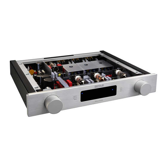
Page 10: Top View
4. MAIN UNIT 4.2. Top View Legend Sliding switch for the In delivery state where the Filter is on (see chapter. 4.6.). Subsonic Filter Additional connections for the Line Input Modules IN 4 (see Flat Wire Connector chapter. 5.4) and IN 8 (see chapter 5.7.) You can connect one or two Line Input Modules (maximum 2 pc). -
Page 11: Rear View
4. MAIN UNIT 4.3. Rear View Legend Connector for the optional external power supply enhancement PSU Booster (Power module. Supply Unit Booster) Connector for the external power supply. Power Supply Con- nector Placement of the Modules: Line In input moduls only slot 2 or 3 Phono input moduls slot 1, 2 or 3... -
Page 12: Installing The Modules
4. MAIN UNIT 4.4. Installing the Modules Caution! The modules should always be replaced by a specialist! Example for mounting an Input Module in slot 2 Please ensure that the unit is switched off and disconnected from the mains. Procedure Unscrew the six TORX screws with the supplied hexagon screwdriver SW2 from the top cover plate and remove the plate. -
Page 13: External Power Supply
4. MAIN UNIT 4.5. External Power Supply Power Supply front Legend I = ON Mains power switch Control LED Power Supply rear panel Legend IEC receptacle Mains Input and Mains Voltage Serial Number with Plug Connector Connecting Cable... -
Page 14: Tube Layout, Replacing Tubes
4. MAIN UNIT 4.6. Tube layout, replacing tubes Tube Layout: ECC88 ECC81 ECC83 Tube (ECC83, 12AX7) is the Input Tube. Please use Low Noise Tubes of high quality with matched systems. Tube (ECC81, 12AT7) is for the Main Amplification Stage. Tube (ECC88, 6922, 6N23, 6N1,) is for the Output Buffer. -
Page 15: Subsonic Filter
4. MAIN UNIT 4.7. Subsonic Filter Subsonic Filter Uneven records and mismatched cartridge – tonearm combinations can result in low frequency signals in the range below 15 Hz (addi- tional to the music reproduction). Signals of this low frequency cause excessive swing of the bass driver membrane, especially if it’s a bass- slide switch rexlex system. - Page 16 4. MAIN UNIT 4.7. Subsonic Filter Frequency Response of the Phono Module ( RIAA Curve ) with and without Subsonic Filter: Flat Graph, Fre- quency Response without Subsonic Filter Descending Graph, Frequency Response with Subsonic Filter Low Frequency Signals below 20 Hz will be reduced through the Subsonic Filter by 12 dB / Octave.
-
Page 17: Options
5.1. Option Remote Control (when used as a preamplifier) Of course it is also possible to use the Phono Module with the output modules OUT2 or OUT3 as a preamplifier and to connect it directly to the power amplifier. In this case it is helpful to have a remote control available for volume control. -
Page 18: Option Black Box Preamp
5.2. Option Black Box Preamp Description An external upgrade of the power supply of the Octave Phono Module, the Black Box Preamp fea- tures a sophisticated circuit with superior capacitors (produced in the EU and sourced from EPCOS), and serves to increase the current flow while making the power supply immune to mains power fluctuations. -
Page 19: Available In- And Outputs
See separate operating instructions "Input and output modules". in the cover sheet of this instruction manual. The modular structure of the new phono module enables a multitude of possibilities on both the input and output side, which leave nothing to be desired for both phono and high-level listeners. Different line and phono input modules are available up to the step-up transformer and 3 output modules. -
Page 20: Troubleshooting
Such a device has no adverse affect on the sound or picture quality of tuners or TVs. The Phono Module is not grounded and therefore cannot cause ground loops. Clicks and pops Older fridges and 12 V halogen lamps can cause cracking through the loudspeakers when they are switched on and off. -
Page 21: Technical Data
> 80 dB Crosstalk, L to R / Line 100 dB Crosstalk, Module to Module Subsonic Filter Cut Off Fre- 15 Hz / - 3 dB / 12 dB / Octave quency General Data 35 W Power Consumption Weight Phono Module 7.0 kg... -
Page 22: Technical Data, Diagrams
8. TECHNICAL DATA 8.2. Technical data, diagrams Tolerance RIAA-Equalization The Equalization follows the RIAA Curve within the Tolerance of 0.2 dB in the frequency range of 10 Hz to 50 kHz. This precision requires a equalization network with a maximum de- viation of 0.1 %. - Page 23 First ( 1 ) the stray field of a room without transformer, the stay field of the shielded transformer of the Octave Phono Module ( 2 ), and the stray field of a conventional transformer ( 3 ).
- Page 24 We reserve the right to alter and improve the specifications in pursuit of better. OCTAVE logo is a registered trade mark of Andreas Hofmann. Copyright by Andreas Hofmann. Reproduction in whole or part is prohibited. OCTAVE AUDIO Germany www.octave.de...
Need help?
Do you have a question about the PHONO MODULE and is the answer not in the manual?
Questions and answers