Table of Contents
Advertisement
Quick Links
Advertisement
Table of Contents

Subscribe to Our Youtube Channel
Related Manuals for Octave V110


Summary of Contents for Octave V110
- Page 1 V 110...
-
Page 2: Introduction
10 years ago. These advances have been achieved through the application of the latest technological developments as they become available and affordable. OCTAVE has specialized in tube amplification for the past 25 years, during which time we have developed a number of innovative technologies that have earned us a reputation as one of the leaders in the field. -
Page 4: Table Of Contents
CONTENTS Page Introduction ....................Description of the V 110 ................Safety instructions ..................Before you begin ..................Placement ....................Warranty ....................... Getting started ....................Unpacking, package contents ..............Removing the grille ..................Installing the power tubes ................Switching on for the first time: the soft-start feature ........Checking the tubes (BIAS) ................ -
Page 6: Description Of The V 110
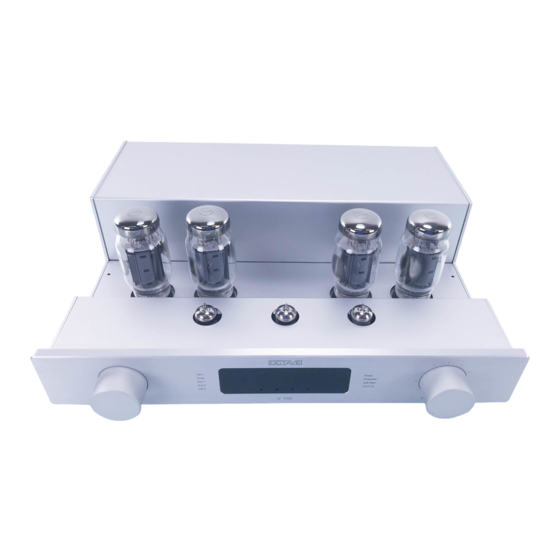
1. DESCRIPTION OF THE V 110 The Octave V 110 integrated amplifier is a push-pull pentode design delivering 2 x 110 W RMS output power (into 4 ohm loads). As with all Octave models, all research and development (R&D) and production has been conducted exclusively in-house, and the amplifier is comprehensively safeguarded against user error and parts wear –... -
Page 7: Safety Instructions
Servicing and maintenance For reasons of safety, please ensure that any servicing, repairs or other modifications to OCTAVE equipment are carried out only by a qualified technician. Always get an engineer to replace blown fuses with ones of the same type and rating. -
Page 8: Placement
2.2. Placement 1. Location OCTAVE equipment is designed strictly for use in a dry domestic environment. Do not use it in the open air or in damp environments! Never place plants or liquid-filled containers on your OCTAVE equipment. Take care to avoid dropping objects or spilling liquids into the case. -
Page 9: Getting Started
3. GETTING STARTED 3.1. Unpack and check the contents of the box. outer inside owner's manual and carton carton warranty card tube power cord remote compartment and tools control Package contents standard V 110 serial equipped with KT120 power tubes 5 power tubes packed separately Power cord Remote control with owner's manual... -
Page 10: Installing The Power Tubes
3. GETTING STARTED 3.3. Installing the power tubes The power tubes are in a separate box in the tube compartment Insert the power tubes into their sockets as shown on the tube layout. Ensure that you correctly locate the anti-rotation lug on each of the tubes. Anti-rotation recess on the tube socket 3.4. -
Page 11: Checking The Tubes (Bias)
3. GETTING STARTED 3.5. Checking the power tubes – setting the BIAS 4) Turn the mode selector knob clockwise to position 6 = BIAS. The input LEDs will extinguish. 5) Five LEDs will now illuminate: The power LED and the 4 BIAS LEDs in the center of the display, one for each power tube. -
Page 12: Connection Options: Overview
3. GETTING STARTED 3.7. Connection options: overview... -
Page 13: Front Panel Controls
4. CONTROLS – the front panel Power switch 0 = off; 1 = on. Power LED and Soft-Start LED illuminate. The Soft- Start LED extinguishes after the start-up period of 50 seconds. Input selector This is used to select the desired input signal. A blue LED indicates the selected input on the display. - Page 14 4. CONTROLS – the front panel BIAS adjustment BIAS regulators and corresponding LED array for each power tube. Remote control receiver To ensure optimum operation of the IR remote control, do not cover this window. Status indicators Power Indicates that the unit is switched on.
-
Page 15: Rear Panel Connections
6. CONNECTIONS – the rear panel Ecomode Ecomode Eco off: Ecomode automatic is off. Eco on: Ecomode automatic is on. Amp off: The power stage of the amplifier is off (see chap. 6.4.). CD line level input, RCA. CD 1 Tuner Tuner line level input, RCA. - Page 16 6. CONNECTIONS – the rear panel CD 2 Pin configuration for XLR connectors (CD line level input, XLR see previous page 17) Speaker connection terminals. Loudspeaker outputs Red = positive terminal, Black = negative terminal. The speaker negative terminal is connected to ground. (Super) Black Box The (Super) Black Box is an outboard power supply connection...
-
Page 17: Advanced Functions And Connection Options
6. ADVANCED FUNCTIONS 6.1. Power Selector, alternative output tubes Position „HIGH“: KT120 Position „LOW“: KT88, 6550, KT90, KT100 (EL34 with Restrictions) The Power Selector allows adjusting the V 110 in accordance to the output tubes. Position HIGH is reserved for the standard KT 120 tubes. In the HIGH Position the V 110 is able to deliver up to 2 x 110 W RMS Output Power. -
Page 18: Protection
6. ADVANCED FUNCTIONS 6.2. Protection The V 110 features a comprehensive electronic monitoring and protection system. This system will automatically switch off the V 110 if case of a fault occurring in the power section. The protection system has been designed to keep the unit safe from the consequences of overloads of any kind and to protect the output tubes from current surges. -
Page 19: Ecomode
6. ADVANCED FUNCTIONS 6.4. Ecomode The Ecomode serves to reduce heat and unnecessary power consumption when the unit is switched on but not in use. After 9 minutes without receiving signal, the V 110 Ecomode is activated, turning down the power. In this “sleep” mode, the V 110 draws less than 20 W Idle current. -
Page 20: Front Channel
6. ADVANCED FUNCTIONS 6.5. Front Channel Input - Bypass function The Input labeled “Front Channel“ is coupled with a relay that bypasses the volume regulator. In the “Front Channel” selector position, the V 110 functions as a stereo amplifier. The overall Gain of the V 110 is reduced to 26dB in this position. -
Page 21: Tubes
7. TUBES 7.1. Removing the grille See chapter 3.2. 7.2. Tube layout Output tubes: V1 - V4: KT120 standard V1 + V2 left channel V3 + V4 right channel Driver tubes: ECC83 (12 AX 7) V6 + V7 ECC81 (E 81CC, 12AT 7) alternatively 2 x ECC 82 (12 AU7) The pentode output stage topology of the V 110 makes it possible to use of a variety of output tubes. -
Page 22: Bias Measurement System
7. TUBES 7.3. THE BIAS MEASUREMENT SYSTEM The BIAS measurement facility makes it easy for you to check and adjust the idle current of the output tubes. Getting the BIAS setting right for all four tubes is critical for both the sound of the power amplifier section and for the service life of the tubes. - Page 23 7. TUBES There is an upper adjustment limit to the "high" BIAS setting, which is indicated by the green and red LEDs lighting up at the same time, and a lower limit to the "low setting, where the yellow and green LEDs light up.
-
Page 24: Replacing The Tubes
You should adjust these tubes after about 20 minutes. 7.5. Running in All OCTAVE equipment is subject to a 48-hour soak test at the factory to burn in the tubes. The tubes are preselected for use in each particular model. -
Page 25: Remote Control
MC and MM systems. Specification: Input impedance: MC 150 ohm, MM 47k ohm Signal-to-noise ratio MC 73 dB, MM 85 dB Input sensitivity MC 0.5 mV, MM 4 mV Subsonic filter -12 dB/Octave; 20 Hz cut off frequency... -
Page 26: Using Black Box Or Super Black Box
OCTAVE, with the Black Box technology, offers an instrument for optimizing the OCTAVE amplifier in respect to the speaker. This flexibility is a unique feature of the OCTAVE brand. The dynamic and tonal stability of an amplifier is strongly dependent upon the stability and capacity of the power supply, therefore the Black Box and Super Black Box were developed as external upgrades to the OCTAVE amplifiers’... -
Page 27: The Super Black Box Option
10. USING BLACK BOX OR SUPER BLACK BOX 10.2. Super Black Box option Operation Blue power LED The blue "power" LED illuminates when the power amplifier (or integrated amplifier) is switched on via the amplifier's power on/off switch. Yellow unload LED The yellow "unload"... -
Page 28: Troubleshooting
11. TROUBLESHOOTING 11.1. Faults caused by external issues Buzzing and hum in the speakers Possible cause: multiple grounds Hum in an audio system is often caused by several system components having their own separate grounds. It is particularly common in systems containing tuners, VCRs or satellite receivers, as these components are connected to an aerial. - Page 29 11. TROUBLESHOOTING Possible cause: induction Another possible cause of hum could be the stray field of a transformer generating interference in a device or cable. You can easily diagnose this problem by switching off the problem component. To fix the problem To reduce this kind of interference, move the transformer/component or the affected component/cable to a different location.
-
Page 30: Faults Caused By Tubes
11.2. Faults caused by tubes, faulty tubes Like other OCTAVE products, the V 110 is equipped with a double safety system. This means that the amplifier will be protected from damage if a component (tube) should fail and trip the electronic protection. - Page 31 11. TROUBLESHOOTING Tube faults that trip the protection system The protection system continuously measures the current flowing into the four power tubes. Depending on the problem, this current may exceed a specified limit and cause the protection system to switch the power stage off. The red protection LED will light up to show that this has happened.
-
Page 32: Specifications And Dimensions
12. SPECIFICATIONS AND DIMENSIONS In- and Outputs: Inputs: 5 x RCA, 1 x XLR 1 x RCA Home Theatre Bypass input Outputs: 1 x RCA Record Output, 1 x Regulated Preamplifier Output, 1 x Loudspeaker Output Power amplifier Output Configuration: Push Pull, advanced Pentode Mode, Grid 2 Voltage 340 V, Idle Current Tubes 28 mA - BIAS Low, 34 mA - BIAS High. - Page 33 12. SPECIFICATIONS AND DIMENSIONS Diagrams THD at 4V into 4 ohms from 30 Hz to 20 kHz at a variety of BIAS settings Diagramm 1 Curve 1: BIAS adjusted correctly Curve 2: BIAS 10% out Curve 3: BIAS 30% out...
- Page 34 12. SPECIFICATIONS AND DIMENSIONS Graph 2: Frequency response, 5 W into 4 ohms Audio Precision Frequency Response V 70 SE 5 V / 4 Ohm The frequency response curve clearly shows the low frequency extension of the V 110 linear to 10 Hz The loss at 20 Hz is less than 0,2 dB Graph 3: Noise spectrum A-A FFT SPECTRUM ANALYSIS V 70 SE 5 V / 4 Ohm...
-
Page 35: Frequently Asked Questions (Faq)
Can you operate the V 110 when no loudspeakers are connected? Yes. The V 110, like all OCTAVE amplifiers, is fully protected against open circuit operation, i.e. the amplifier will come to no harm if it is operated without loudspeakers connected. - Page 36 We reserve the right to alter and improve the specifications in pursuit of better. OCTAVE logo is a registered trade mark of Andreas Hofmann. Copyright by Andreas Hofmann. Reproduction in whole or part is prohibited. edited EN2012 OCTAVE AUDIO Germany...
Need help?
Do you have a question about the V110 and is the answer not in the manual?
Questions and answers