Table of Contents
Advertisement
D
i
g
i
t
a
l
O
D
i
g
i
t
a
l
O
D
i
g
i
t
a
l
O
2
-
c
h
a
n
2
-
c
h
a
n
2
-
c
h
a
2
-
c
h
a
n
2
-
c
h
a
n
2
-
c
h
a
U
s
e
r
'
s
m
U
s
e
r
'
s
m
U
s
e
r
'
s
Tel. +33 (0)1.44.85.44.85 - Fax +33 (0)1.46.27.73.89
s
c
i
l
l
o
s
c
s
c
i
l
l
o
s
c
s
c
i
l
l
o
s
c
X
D
O
2
X
D
O
2
X
D
O
2
n
e
l
-
2
5
n
e
l
-
2
5
n
n
e
l
-
2
5
X
D
O
2
X
D
O
2
X
D
O
2
n
e
l
-
4
0
n
e
l
-
4
0
n
n
e
l
-
4
0
a
n
u
a
l
a
n
u
a
l
m
a
n
u
a
l
Group CHAUVIN ARNOUX
190, rue Championnet
F - 75018 - PARIS
X03583A00 - Ed. 01 - 09/10
o
p
e
s
o
p
e
s
o
p
e
s
0
2
5
0
2
5
0
2
5
M
H
z
M
H
z
M
H
z
0
4
0
0
4
0
0
4
0
M
H
z
M
H
z
M
H
z
Advertisement
Table of Contents

Related Manuals for Chauvin Arnoux Multimetrix XDO2025


Summary of Contents for Chauvin Arnoux Multimetrix XDO2025
- Page 1 ’ ’ ’ Group CHAUVIN ARNOUX 190, rue Championnet F - 75018 - PARIS Tel. +33 (0)1.44.85.44.85 - Fax +33 (0)1.46.27.73.89 X03583A00 - Ed. 01 - 09/10...
-
Page 2: Table Of Contents
Content Content General Instructions Introduction..................4 Precautions and safety measures ..........4 Symbols on instrument..............5 Guarantee, Repair, Servicing ............5 Instrument Description Front panel ..................6 XDO2025 - XDO2040.......6 Rear panel ..................10 XDO2025 - XDO2040......10 Functional Description AUTO Setup ............................11 Auto Setup, screen, symbol ............11 Autoset function menu......12 VERTICAL System ..........................13 CH1 - CH2 Channel.................13... - Page 3 General instructions Content (cont’d) Alternative Trigger................31 Edge Trigger function menu......31 Pulse Trigger function menus......32 Video Trigger function menus......33 Slope Trigger function menus ......34 Trigger Holdoff................36 ACQUISITION System ..........................37 Acquiring Signal System ...............37 Acquiring signal function menu......37 DISPLAY System ..........................38 Display System ................38 Display system function menus......38 X-Y Format ..................41 MEASURE System ..........................42...
-
Page 4: General Instructions
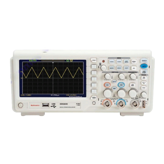
General Instructions General Instructions Introduction You have just acquired a 2-channel digital oscilloscope : • XDO2025, 25 MHz or • XDO2040, 40 MHz. This 2-channel oscilloscope provides a set of powerful features for a wide range of applications such as production, education, maintenance, service, research and development. -
Page 5: Symbols On Instrument
General instructions General Instructions (cont’d) Symbols on Warning: Risk of danger. instrument Refer to the operating manual to find out the nature of the potential hazards and the action necessary to avoid such hazards. Selective sorting of waste for recycling electric and electronic materials. -
Page 6: Instrument Description
Instrument Description Instrument Description Front panel XDO2025 XDO2040 14 13 Dual-Channel Digital Oscilloscopes... - Page 7 Instrument Description Instrument Description (cont’d) Front panel (cont’d) Power ON / Power OFF 1 - POWER 2 - USB USB HOST interface connection 3 - MENU MENU ON / OFF 4 - CH1 - CH2 Input connectors for waveform display Input connector for an external trigger source.
- Page 8 Instrument Description Instrument Description (cont’d) VERTICAL System Volt/div. knobs (see p. 14). 19 - POSITION Channel 1, Channel 2 menu control button 20 - CH1 - CH2 keys MATH function control button 21 - MATH Reference waveforms control button, saves waveforms to a non volatile 22 - REF memory.
- Page 9 Instrument Description Instrument Description (cont’d) MENU key pad 31 - CURSORS Displays the cursor menu (see p. 41). Vertical Position controls adjust cursor position while displaying the Cursor Menu and the cursors are activated. Cursors remain displayed (unless the “Type” option is set to “Off”) after leaving the Cursor menu but are not adjustable.
-
Page 10: Rear Panel
Instrument Description Instrument Description (cont’d) Rear panel XDO2025 37 - Pass / Fail PASS / FAIL output 38 - RS 232 RS 232 connector 39 - USB Back USB connector 40 - Plug Power input connector XDO2040 41 - Pass / Fail PASS / FAIL output 42 - RS 232 RS 232 connector 43 - USB Back USB connector 44 - Plug Power input connector... -
Page 11: Functional Description
Functional Description Functional Description AUTO Setup Auto Setup Autoset determines the trigger source based on the following conditions: ● If multiple channels have signals: channel with the lowest frequency signal. ● No signals found: the lowest-numbered channel displayed when Autoset was invoked. ●... -
Page 12: Autoset Function Menu
Functional Description Functional Description AUTO Setup (cont’d) Autoset function menu Function Setting Acquire Mode Adjusted to Sampling Display Format Display Type Set to Dots for a video signal, set to Vectors for an FFT spectrum; otherwise, unchanged Vertical Adjusted to DC or AC according to the input Coupling signal Bandwidth... -
Page 13: Vertical System
Functional Description Functional Description VERTICAL System CH1 - CH2 Channel CH1 & CH2 function menu 1 Option Setting Description Coupling DC passes both AC and DC components of the input signal. AC blocks the DC component of the input signal and attenuates signals below 10 Hz. GND disconnects the input signal. -
Page 14: Ch1 & Ch2 Function Menus
Functional Description Functional Description VERTICAL System (cont’d) CH1 & CH2 function menu 2 Option Setting Description Turn on invert function. Invert Turn off invert function. Turn the “Universal knob” to adjust them. Digital Press this button to enter the “Digital Filter Filter menu”. -
Page 15: Knobs In The Vertical Mode
Functional Description Functional Description VERTICAL System (cont’d) Knobs in the « VERTICAL » mode 1. Use the Vertical “POSITION” knobs to move the channel waveforms Vertical “POSITION” up or down on the screen. knob 2. When you adjust the vertical position of channels waveforms, the vertical position information will be displayed on the bottom left of screen. -
Page 16: Math Functions
Functional Description Functional Description VERTICAL System (cont’d) MATH functions This shows the results after +, -, ∗ and FFT operation of the CH1 and CH2. Press the MATH button to display the waveform math operations. MATH Function Setting Description function menu Operation +, -, *, FFT Choose MATH operations. -
Page 17: Fft Spectrum Analyser
Functional Description Functional Description VERTICAL System (cont’d) FFT Spectrum Analyser The FFT process mathematically converts a time-domain signal into its frequency components. You can take two measurements on FFT spectrums: magnitude (in dB) and frequency (in Hz). FFT Option Setting Description FFT function menu 1 Source... -
Page 18: Measuring An Fft Spectrum Using Cursors
Functional Description Functional Description VERTICAL System (cont’d) Measuring an FFT Spectrum using cursors You can take two measurements on FFT spectrums : magnitude (in dB) and frequency in Hz. Measuring an FFT amplitude Once viewed the spectrum : 1. Press the “CURSOR” button to enter “Cursor” menu. 2. -
Page 19: Measuring Fft Frequency
Functional Description Functional Description VERTICAL System (cont’d) Measuring FFT frequency 1. Press the CURSOR button. 2. Press “Cursor Mode” to select “Manual”. 3. Press “Type” to select “Time”. 4. Press “Source” to select “MATH”. 5. Press “Cur1”, turn the “Universal” button to move Cursor 1 to the highest position of the FFT waveform. -
Page 20: Using Ref
Functional Description Functional Description VERTICAL System (cont’d) Using REF The reference control saves waveforms to a non-volatile waveform memory. The reference function becomes available after a waveform has been saved. REF function menu Press the « REF » button. Option Setting Introduction Source... -
Page 21: Horizontal System
Functional Description Functional Description HORIZONTAL System HORIZONTAL System Horizontal system function menu Option Setting Description Delayed Turn on this function in order to simultaneously display the main waveform time base on the top half of the screen and the window time base waveform on the bottom half of the screen Turn off this function in order to display only the main waveform time base on the screen. -
Page 22: Knobs In Horizontal Mode
Functional Description Functional Description HORIZONTAL System (cont’d) Knobs in the « Horizontal » mode You can use the horizontal controls to change the horizontal scale and position of waveforms. 1. Adjust the horizontal position of all channels and math waveforms Horizontal (the position of the trigger relative to the centre of the screen). -
Page 23: Trigger System
Functional Description Functional Description TRIGGER System TRIGGER System The trigger determines when the oscilloscope starts to acquire data and to display a waveform. XDO series has five trigger type : Edge, Video, Pulse, Slope, Alternative Signal source The source can be any signal connected to a channel BNC, to the EXT TRIG BNC or the AC power line (available only with Edge triggers). -
Page 24: Trigger Setup Function Menu
Functional Description Functional Description TRIGGER System (cont’d) Trigger Setup function menu Option Setting Description Coupling Passes all components of the signal Blocks DC components and attenuates signals below 10 Hz. Attenuates the high-frequency components HF Reject above 80 kHz. Blocks the DC component and attenuates LF Reject the low-frequency components below 300 kHz. -
Page 25: Pulse Trigger
Functional Description Functional Description TRIGGER System (cont’d) Pulse Trigger Pulse Trigger function menu 1 Option Setting Description Type Pulse Select the pulse to trigger the pulse match the trigger condition. Source Select input signal source. EXT/5 When (Positive pulse width Select how to compare the less than pulse width trigger pulse relative to the... - Page 26 Functional Description Functional Description TRIGGER System (cont’d) Pulse Trigger function menu 2 Option Setting Description Type Pulse Select the pulse to trigger the pulse match the trigger condition. Auto Mode Select the type of triggering; Normal mode Normal is best for most Pulse Width trigger applications.
-
Page 27: Video Trigger
Functional Description Functional Description TRIGGER System (cont’d) Video Trigger Video Trigger 1 function menu Option Setting Instruction Type Video When you select the video type, set the AC coupling, it then becomes possible to trigger the NTSC, PAL and SECAM video signal. - Page 28 Functional Description Functional Description TRIGGER System (cont’d) Video Trigger 1 function menu Option Setting Instruction Type Video When you select the video type, set the AC coupling, then you could trigger the NTSC, PAL and SECAM video signal. Standard NTSC Select the video standard for sync and line number count.
-
Page 29: Slope Trigger
Functional Description Functional Description TRIGGER System (cont’d) Slope Trigger Slope Trigger function menu 1 Option Setting Instruction Type Slope Trigger on positive slope of negative slope according to setup time of the oscilloscope. Source Select trigger source. EXT/5 When Select trigger condition. Time Turn the “Universal”... - Page 30 Functional Description Functional Description TRIGGER System (cont’d) Slope Trigger function menu 2 Option Setting Instruction Type Slope Trigger on positive slope of negative slope according to setup time of the oscilloscope. Vertical Select the trigger level that can be adjusted by “LEVEL” knob. You can adjust “LEVEL A”, “LEVEL B”...
-
Page 31: Alternative Trigger
Functional Description Functional Description TRIGGER System (cont’d) Alternative Trigger The trigger signal comes from two vertical channels when you use the alternative trigger. In this mode, you can observe two irrelative signals at the same time. You can select different trigger types for two vertical signals and selected types cover edge, pulse, video and slope trigger. -
Page 32: Pulse Trigger Function Menus
Functional Description Functional Description TRIGGER System (cont’d) Pulse Trigger function menu 1 Option Setting Instruction Type Alternative The trigger signal comes from two vertical channels when you use alternative trigger. In this mode, you can observe two irrelative signals at the same time. Set trigger type information for CH1 signal Source Set trigger type information for CH2 signal... -
Page 33: Video Trigger Function Menus
Functional Description Functional Description TRIGGER System (cont’d) Video Trigger function menu 1 Option Setting Instruction Type Alternative The trigger signal comes from two vertical channels when you use alternative trigger. In this mode, you can observe two non- related signals at the same time. Source Set trigger type information for CH1 signal Set trigger type information for CH2 signal... -
Page 34: Slope Trigger Function Menus
Functional Description Functional Description TRIGGER System (cont’d) Slope Trigger function menu 1 Option Setting Instruction Type Alternative The trigger signal comes from two vertical channels when you use alternative trigger. In this mode, you can observe two non- related signals at the same time. Set trigger type information for CH1 signal Source Set trigger type information for CH2 signal... - Page 35 Functional Description Functional Description TRIGGER System (cont’d) to observe two irrelative channel signals : Follow these steps Input two irrelative signals to channel 1 and channel 2. Press the AUTO button. Press TRIG MENU to enter “trigger menu”. Press “Type” to select “Alternative”. Press “Source”...
-
Page 36: Trigger Holdoff
Functional Description Functional Description TRIGGER System (cont’d) Trigger Holdoff You can use the Trigger Holdoff function to produce a stable display of complex waveforms. Holdoff is the time between when the oscilloscope detects one trigger and when it is ready to detect another one. If you want to change the holdoff time, follow these steps: Press the “TRIG MENU”... -
Page 37: Acquisition System
Functional Description Functional Description ACQUISITION System Acquiring Signal When you acquire a signal, the oscilloscope converts it into a digital System form and displays a waveform. The acquisition mode defines how the signal is digitized and the time base setting affects the time span and level of detail for the acquisition. -
Page 38: Display System
Functional Description Functional Description DISPLAY System DISPLAY System Display system Press the “DISPLAY” button. function menu 1 Option Setting Description Type Vectors "Vectors" fills the space between adjacent sample points in the display. Dots Dots : display sample points Directly. Persist Sets the length of time for which each displayed sample point will be... - Page 39 Functional Description Functional Description DISPLAY System (cont’d) Display system function menu 2 Option Setting Description Format YT format displays the vertical voltage in relation to time (horizontal scale). XY format displays a dot each time a sample is acquired on channel 1 and channel 2.
- Page 40 Functional Description Functional Description DISPLAY System (cont’d) Display system function menu 3 Option Setting Description Skin Classical Set up screen style. Modern Tradition Succinct Dual-Channel Digital Oscilloscopes...
-
Page 41: X-Y Format
Functional Description Functional Description DISPLAY System (cont’d) X-Y Format Use the XY format to analyze phase differences. The format plots the voltage on channel 1 against the voltage on channel 2, where channel 1 is the horizontal axis and channel 2 is the vertical axis. The oscilloscope uses the untriggered Sample acquisition mode and displays data as dots. -
Page 42: Measure System
Functional Description Functional Description MEASURE System The oscilloscope displays the voltage in relation to time and tests the wave form displayed. There are scale, cursor and auto measure modes. Scale Measurement This method allows you to make a quick visual estimate. Cursor Measurement The cursor measurement has three modes: Manual, Track and Auto. -
Page 43: Track Mode Function Menu
Functional Description Functional Description MEASURE System (cont’d) Track mode function menu Option Setting Description Track Cursor Mode In this mode, set track cursor measure. Cursor A Set the input signal channel that the Cursor A will measure. NONE Cur B Set the input signal channel that the Cursor B will measure. -
Page 44: Auto Mode Function Menu
Functional Description Functional Description MEASURE System (cont’d) Auto mode function menu Option Setting Description Cursor Mode Auto Set to auto cursor measure mode. This mode will take effect with automatic measurements. to perform auto cursor measurements : Follow these steps 1. -
Page 45: Auto Measurement
Functional Description Functional Description MEASURE System (cont’d) Auto Measurement Press the ‘MEASURE’ button for the Automatic Test. There are three auto measurement types: Voltage Measure, Time Measure and Delay Measure. There are 32 measure parameters. Auto measure function menu 1 Option Instruction Voltage... -
Page 46: Auto Mode Function Menu : Time Measure
Functional Description Functional Description MEASURE System (cont’d) Auto measure function menu 3 Time measure menu Option Setting Instruction Source CH1 CH2 MATH Select input signal source REFA REFB for Voltage measure. Type Rise Time Fall Time Freq Press the “Type” button or Period BWidth +Width turn the “Universal”... -
Page 47: All Measurement Function Menu
Functional Description Functional Description MEASURE System (cont’d) All measurement function menu Option Setting Description Source Select input signal channel. Voltage Turn on the all measurement function to measure voltage parameters. Turn off the all measurement function to measure voltage parameters. Time Turn on the all measurement function to measure Time parameters. - Page 48 Functional Description Functional Description MEASURE System (cont’d) All measurement function menu (cont’d) Defined as (Vmax-Vhig)/Vamp after the waveform ROVShoot rising. Defined as (Vmin-Vlow)/Vamp after the waveform FOVShoot falling. Defined as (Vmin-Vlow)/Vamp before the waveform RPREshoot rising. Defined as (Vmax-Vhig)/Vamp before the waveform FPREshoot falling.
-
Page 49: Storage System
Functional Description Functional Description STORAGE System STORAGE System The XDO series can save 2 group reference waveforms, 20 group setups and 20 group waveforms to the oscilloscope’s internal memory. There is a USB Host interface on the front panel of the oscilloscope and it is possible to save setup data, waveform data, waveform interface image, CSV file to a USB flash drive. -
Page 50: Save / Recall
Functional Description Functional Description STORAGE System (cont’d) Modify the file name Return to the last menu Save / Recall setups The complete setup is stored in non-volatile memory. The oscilloscope saves the current setup provided you wait three seconds after the last change before powering off the oscilloscope. The oscilloscope will recall this setup the next time you turn it on. -
Page 51: Save / Recall Setups To Usb Flash Drive
Functional Description Functional Description STORAGE System (cont’d) To save setups to the oscilloscope’s internal memory or to recall saved Follow these steps setups. For example: to save the setup so that the oscilloscope displays the waveform as “Dots” to the oscilloscope’s internal memorizer. 1. - Page 52 Functional Description Functional Description STORAGE System (cont’d) To save setups to the USB flash drive : Follow these steps For example: to save setup so that the oscilloscope displays the waveform as “Dots” to the oscilloscope’s internal memory. 1. Press the “SAVE/RECALL” button to select “Setups”. 2.
-
Page 53: Recall Factory Setup
Functional Description Functional Description STORAGE System (cont’d) To recall the factory setup : Recall Factory Option Setting Description Type Factory To view the Factory setup. Load Recall the Factory setup. Save / Recall The oscilloscope will display the waveforms that you want to save. The waveform oscilloscopes can store twenty captured waveforms to a non volatile memory. -
Page 54: Save / Recall Waveform To Usb Flash Drive
Functional Description Functional Description STORAGE System (cont’d) Follow these steps To save a waveform to the internal memory: 1. Press the “SAVE/RECALL” button to enter “SAVE/RECALL” display menu. 2. Press the “Type” button to select “waveforms”. 3. Press “Save to” to select “Device”. 4. - Page 55 Functional Description Functional Description STORAGE System (cont’d) To save a waveform to a USB flash drive : Follow these steps 1. Input a sine signal to channel 1, press the “AUTO” button. 2. Press “SAVE/RECALL” to enter the “SAVE/RECALL” display menu. 3.
-
Page 56: Save Picture
Functional Description Functional Description STORAGE System (cont’d) Save Picture The waveform interface image can be saved to a USB flash drive, but can’t be recalled. You can open these using adequate computer software. Option Setting Description Type Pictures Menu for the Storage/Recall of waveform interface image. -
Page 57: Save / Recall Reference Waveform
Functional Description Functional Description STORAGE System (cont’d) Save / Recall The oscilloscopes can store two reference waveforms to non volatile memory. Reference Waveform The oscilloscope can display reference waveforms at a time. Reference waveforms are not adjustable, but the oscilloscope displays the horizontal and vertical scales at the bottom of the screen. -
Page 58: Utility System
Functional Description Functional Description UTILITY System (cont’d) UTILITY System Press the “ UTILITY “ button. Utility System function menu 1 Option Setting Description System Displays a summary of the Status oscilloscope settings. Sound Open the key-press voice. Close the key-press voice. Counter Turn on Frequency Counter Turn off Frequency... - Page 59 Functional Description Functional Description UTILITY System (cont’d) Utility System function menu 2 Option Setting Description DO self Auto self calibration Do Self Screen Run the screen detect program Test Test Keyboard Run the keyboard detect program Test Run the dot lighting detect program. LED Test Print Enter the print setup menu to set print...
- Page 60 Functional Description Functional Description UTILITY System Utility System function menu 3 Option Setting Description Update You can update the oscilloscope firmware using a USB flash Driver. Pass/Fail Press this button to enter the “Pass/Fail menu”. Record Press this button to enter the waveform record menu.
- Page 61 Functional Description Functional Description UTILITY System (cont’d) Utility System function menu 4 Option Setting Description Screen- 1 min 2 min Set the time for the screen-saver saver 5 min 10 min 15 min 30 min 1 hour 2 hours 5 hours off Function checking To check that oscilloscope is running smoothly, proceed as follows: Set the switch to 1x on the probe and connect the...
-
Page 62: System Status
Functional Description Functional Description UTILITY System (cont’d) System Status Select “System Status” from the Utility Menu to display information pertaining to this oscilloscope. Instructions You can connect a printer using a USB cable. Print Option Setting Description Print setup option function menu 1 Ink Saver Prints the screen image on a... - Page 63 Functional Description Functional Description UTILITY System (cont’d) Print setup option function menu 2 Option Setting Description Displays Settings Image Size Default, 2.5x3.25 in, L (3.5x5 in), 4x6 in, 2L (5x7 available on your in), 8x10 in, 4L (7 x 10 in), PictBridge compatible E, Card, Hagaki card, 6 x printer.
-
Page 64: Update Firmware
Functional Description Functional Description UTILITY System (cont’d) Update Firmware The software can be updated directly using a USB Flash drive. Follow next steps 1. Insert the USB Flash Drive with firmware. 2. Press the “UTILITY” button. 3. Press “Next Page” to enter the third page of the “Utility menu”. 4. -
Page 65: Pass/Fail
Functional Description Functional Description UTILITY System (cont’d) Pass / Fail The Pass/Fail function can monitor changes in signals and output pass or fail signals by testing whether the input signal is within the predefined mask or not. Pass/Fail function menu 1 Option Setting Description... - Page 66 Functional Description Functional Description UTILITY System (cont’d) Pass / Fail function menu 2 Option Setting Description Output Pass Output when pass condition detected. Fail Output when fail condition detected. Stop On Output Stop test on output Continue test on output. Mask Setting Press this button to enter the “Mask Setting menu”.
-
Page 67: Mask Setting
Functional Description Functional Description UTILITY System (cont’d) Mask Setting Mask Setting function menu 1 Option Setting Description X Mask Turn the “Universal” knob to set the range of horizontal clearance to the waveform. <0.04div-4.00div> xdiv Y Mask Turn the “Universal” knob to set the range of vertical clearance to the waveform. - Page 68 Functional Description Functional Description UTILITY System (cont’d) RUN Pass/Fail test Follow next steps Press UTILITY button to enter the “Utility menu”. Press “Next Page ” to enter the third page of “Utility menu” Press “Pass/Fail” to enter the “Pass/Fail” function menu. Press “Enable Test”...
-
Page 69: Waveform Record
Functional Description Functional Description UTILITY System (cont’d) Waveform Record The waveform recorder can record input waveform from CH1 and CH2, with a maximum record length of 2500 frames. Waveform recorder function menu Option Setting Description Mode Record Set Record function menu. Play Back Set Play Back function menu. -
Page 70: Playback
Functional Description Functional Description UTILITY System (cont’d) Play Back Play back current record waveforms or saved record waveforms. Waveform play back function menu 1 Option Setting Description Mode Play Back Set the Play Back function menu. Operate Press to start playback playing. (Run(... -
Page 71: Recorder
Functional Description Functional Description UTILITY System (cont’d) Recorder The waveform recorder is a type of seamless and no-gap real time recording of waveform. This means that oscilloscope can save and replay the waveforms it captured. This is similar to a waveform recording instrument, and the largest recording size for its internal memory is 6M Waveform recording... - Page 72 Functional Description Functional Description UTILITY System (cont’d) Waveform recalling function menu Option Description Stop Quit the auto-recalled waveform, the waveform in EMS memory can then be observed by changing the time base, the waveform in EMS memory can be moved left and right Previous Recalls previous waveform...
- Page 73 Functional Description Functional Description UTILITY System (cont’d) Recorder setting menu Option Setting Description Viewer Full Waveform full screen recording and channel Screen recalling Split Waveform recording on split screen and channel recalling. CH1 is displayed in the upper half-screen, CH2 is displayed in lower half-screen.
-
Page 74: Technical Specifications
Specifications Technical specifications Inputs AC, DC, GND Input coupling 1 MΩ ± 2 % (|| 17 pF ± 3 pF) Input impedance 400 V (DC + ACp) Max. input voltage x 1, x 10 Probe attenuator x 1, x 5 , x10, x 50, x 100, x 500, x 1000 Probe attenuator factors 4, 16, 32, 64, 128, 256 Averaging... - Page 75 Specifications Technical specifications (cont’d) XDO2025 XDO2040 Horizontal 250 MS/s (2-channel) 500 MS/s (2-channel) Max. sampling rate 500 MS/s (1-channel) 1 GS/s (1-channel) (singleshot) 10 GS/s 25 GS/s Equivalent sampling Measure display main, window, zoom, z window zoom, roll, X-Y modes ±...
- Page 76 Specifications Technical specifications (cont’d) X-Y Mode CH1 input (CH1) X axis CH2 input (CH2) Y axis ≤ 3° X-Y dephasing DC at 50 kHz Measurement types Vcc, Vmax, Vmin, Vamp, Vtop, Vbase, Vavg, Mean, Crms, Vrms, Auto measurements ROVShoot, FOVShoot, RPREShoot, FPREShoot, rise time, fall time, frequency, period + Wid., - Wid ., +Dut, -Dut, BWid, Phase, FRR, FRF, FFR, FFF, LRR, LRF, LFR, LFF...
-
Page 77: General Specifications
Specifications General specifications • Environmental Operating temperature 10° C to 40° C • Storage temperature - 20° C to + 60° C • indoors • Altitude < 3000 m • Relative humidity 95 %, 40° C, 24 h • Power supply Mains voltage 10 - 240 V •...
Need help?
Do you have a question about the Multimetrix XDO2025 and is the answer not in the manual?
Questions and answers