Intel Galileo Hardware Manual
Biobots
Hide thumbs
Also See for Galileo:
- Tutorial manual (32 pages) ,
- User manual (19 pages) ,
- Getting started manual (13 pages)

Related Manuals for Intel Galileo


Summary of Contents for Intel Galileo
- Page 1 Hardware Guide For Intel Galileo...
-
Page 2: Table Of Contents
Contents Hardware Guide Blink Make your Galileo More Make your Galileo Blink Some Using Inputs Using Motors Guide to Debugging... -
Page 3: Make Your Galileo Blink
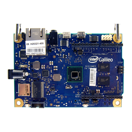
Now you are ready to get started! At this point, plug your Galileo into a power source (Lesson 1, Figure 1), the power light should turn on. Wait a few seconds and the light labeled “usb” will turn on. Once it is turned on, connect the Galileo to the computer using a micro usb cable. - Page 4 In order to program your Galileo, we are going to use the Arduino program (which can also communicate with your Galileo board). Open the Arduino program. On the top bar go to tools -> board and select Intel Gali- leo (Gen 2 if you are using Gen 2), this tells your computer what type of microcontroller you are using. Then, go to tools ->...
- Page 5 The program that opens up when you start the IDE automatically doesn’t do anything. You, the programmer, has to type something to make things happen. For this example, we want to tell the Galileo to blink the light emitting diode (LED) that it has on board (Lesson 1, Figure 3).
- Page 6 Hardware Before you start programming, you have to know a few things. The Galileo is not very smart, you have to type very carefully for it to understand what you want it to do. It has trouble with capitalization, as in it knows what the word ‘OUTPUT’...
- Page 7 Hardware You only need to tell the microcontroller the pin’s mode once, so it should go in your setup function. Your code should now look like this: void setup() { // put your setup code here, to run once: pinMode(13, OUTPUT); //set pin 13 to output, pin 13 is the built-in void loop() { // put your main code here, to run repeatedly: Notice that I wrote a comment after the code I wrote. This helps me know what I was doing when I wrote it, and it makes it easier to come back to the program.
- Page 8 After making sure the program is correct, we can upload, which is the arrow button next to verify. The “upload” button moves the program onto the Galileo, from your computer, so that the microcontroller actu- ally does something. Some things may blink on the microcontroller as it is uploading, but you should see “upload complete” in the bottom black window and your LED should turn on.
- Page 9 Hardware 1.6: Using delay We want our microcontroller to blink, but right now it just stays on. We have to tell the microcontroller to turn on and off. But, we have to leave some time in between so that we can actually see the blinking. delay One way to do this is to use the “...
-
Page 10: Make Your Galileo Blink Some More
2.2: Connecting an LED We have made an onboard (internal) LED light on and off on our Galileo, but now we have to start going ‘off the board’. This means we have to provide a path from the microcontroller to the external LED and back. If we were going to move cars back and forth, we would build a road. - Page 11 Hardware From pin 13, it should go to the LED and back to the Galileo. In order to go back to the Galileo, we have to use one of the pins labeled “GND” (Lesson 2, Figure 2). GND stands for ‘Ground’, which in electronics means a place where electricity likes to go back to.
- Page 12 Hardware Lesson 2 Figure 4 2.3. Challenge Now that you have figured out how to get one external LED to blink, we have a challenge for you! Try to get two LEDs to blink back and forth. In other words, get them to continually switch which is on and which is off. You’ll have to use two LEDs, at least three wires, and the 5V, GND, and pin 13 to do this.
-
Page 13: Using Inputs
An input is anything that gives information to the Galileo. This information is given in the form of electricity, which is the only thing the Galileo understands. An input can give a lot of electricity, a little bit, or something in between. - Page 14 Hardware 3.3: Ways to Wire Up Inputs Buttons A button or switch can be made by simply using any two pieces of metal and touching them together, but they can be made in many shapes and sizes. The button can be placed between 5V and an analog input pin (A0 for example).
- Page 15 Hardware For most inputs (potentiometers, thermsistors, photodiodes, phototransistors) you need to connect both the voltage divider. input and a resistor. They are all connected in a similar configuration, which is called a If you just had the sensor by itself, all the electricity would have to flow through it, regardless of how much resistance it had.
- Page 16 After we tell the microcontroller that we have a variable, we have to assign it a value. This can be done by us- analogRead ing the value from . You can tell the Galileo to assign a value to a variable using an equal sign: myVariable = analogRead(A0); So, the whole program would look like this: void setup(){ pinMode(A0, INPUT); //analog input...
- Page 17 Hardware It would be a wonderful world if we could just write... analogWrite(myVariable, 3); analogRead 1023 ...to write the value read from the sensor to pin . However, the range for is from myVariable and the range for analogWrite is . That means we have to make smaller in order to analogWrite make sure...
- Page 18 Connect one side of the wire to GND on your Galileo board, and the other to your output pin. When you upload the input program (above), you should hear a high pitched noise.
- Page 19 This can also be helpful for seeing if the sensor isn’t working at all. The word serial has to do with how the Galileo sends information back to the computer, which is via a serial port. A library is a collection of code someone else has written, which makes our jobs easier.
- Page 20 You can see these, by opening up tools->Serial Monitor (Lesson 3, Figure 5), after uploading a program with serial stuff onto the Galileo. (Remember to put some delay in your loop or you’ll back up the serial buffer.) In other words, you want to get the microcontroller to display values.
- Page 21 Hardware Serial.print(readValue); //output the read value Serial.print(“\t”); //put a tab between the values to make it easier to read Serial.print(writtenValue); //output the written value Serial.print(“\n”); //Write a new line analogWrite(3, writtenValue); //write to the led delay(100); //delay a bit The program is a lot longer, but it gives nicely formatted data to the serial monitor. And finally, this is what your musical instrument might look like (Lesson 3, Figure 6): Lesson 3, Figure 6 Hardware 21...
-
Page 22: Using Motors
. In the micro- processor world, a shield is a separate chip which allows you to do more with your Galileo, instead of wiring up your own complicated circuit. The motor shield’s purpose is to allow a separate power supply to be used for the motor, and to make moving the motor backwards and forwards easier. - Page 23 Hardware Lesson 4, Figure 1 become hot. The first thing to do is to connect the external power, a 6V or 9V or 12V battery. Connect the negative terminal (-) to GND on the motor shield, and the positive terminal (+) to Vin (not 5V). This will power the motor, and pro- vide a lot more power than otherwise possible.
- Page 24 , you have to write: #include <AFMotor.h> This tells the Galileo that you are using the Adafruit Motor library, so it knows what the functions you are us- ing are. This will save you from having to write your own functions.
- Page 25 To go forward, we have to use two commands: motor.run(FORWARD); This command tells the Galileo that we are going to go forwards with the motor. It does not tell the motor to move, though. motor.setSpeed(125);...
- Page 26 //stop the motor for 1 second Again, test this program to make sure it works. The last thing we need is to tell the motor to go backwards. We tell the Galileo that we want to go backwards by typing: motor.run(BACKWARD);...
- Page 27 When connecting the servo motor notice that there are three wires. These can be various colors (my servo has a red, black and yellow wire) but each color is important to note and goes to a specific spot on the Galileo board.
- Page 28 Hardware Lesson 4, Figure 5 Servo motors do not require as much power as a DC motor so unless you are powering more than one mo- tor a motor shield will not be needed. (Leson 4, Figure 6, 7) Lesson 4, Figure 6 Lesson 4, Figure 7 4.6: Running a Servo Motor Once you have wired your servo motor it’s time to start programming and get it moving.
- Page 29 Now moving onto the setup, we need to connect or servo via the signal wire (yellow wire on my servo) to the Galileo. We are going to attach it to pin 9, the way we can write that is: myservo.attach(9);...
- Page 30 Hardware This is the first function in the Sweep example. The pos=0 is the position we are starting from which in this case we wrote as 0 degrees. The second part is telling the motor to move a total of 180 degrees. Now we need to tell it to stop.
-
Page 31: Guide To Debugging
Hardware Guide to Debugging with the Intel Galileo What is debugging? Debugging is the process of removing and fixing problems in computer programming. It is often the longest and most difficult part of creating a computer program, and requires skill, experience, and patience. A lot of patience. - Page 32 Hardware Diagnosing If your microcontroller is not plugged in, your computer will not be able to communicate with it. This may show up as tools->serial port being grayed out, or the message “transfer incomplete” will show up in your console after pressing “upload”. If you see these try: •...
- Page 33 Hardware >AutoFormat to make your code look nicer. • Use comments Start by writing comments after every line of code. As you gain more experience, use comments for anything weird, potentially confusing, or a problem area. • Don’t write your program all at once Break your program into smaller, testable blocks.
- Page 34 Hardware This is useful to tell if the numbers you are using are wrong, or acting oddly. Print out important numbers, if they are wrong, look into intermediate numbers. Or if that number is from an input, see if the input is correctly hooked up.
Need help?
Do you have a question about the Galileo and is the answer not in the manual?
Questions and answers