Sign In
Upload
Manuals
Brands
Beckhoff Manuals
Control Unit
EP7041-3102
Beckhoff EP7041-3102 Manuals
Manuals and User Guides for Beckhoff EP7041-3102. We have
1
Beckhoff EP7041-3102 manual available for free PDF download: Documentation
Beckhoff EP7041-3102 Documentation (134 pages)
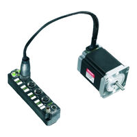
Stepper motor modules
Brand:
Beckhoff
| Category:
Control Unit
| Size: 3 MB
Table of Contents
Table of Contents
3
1 Foreword
5
Notes on the Documentation
5
Safety Instructions
6
Documentation Issue Status
7
2 Product Overview
9
Ethercat Box - Introduction
9
Fig. 1 Ethercat Box Modules Within an Ethercat Network
9
Fig. 2 Ethercat Box with M8 Connections for Sensors/Actuators
10
Fig. 3 Ethercat Box with M12 Connections for Sensors/Actuators
10
Module Overview
11
Fig. 4 EP7041 with Stepper Motor
11
Introduction
12
Ep7041-0002, Ep7041
12
Fig. 5 EP7041-0002
12
Fig. 6 EP7041-2002
13
Ep7041-2002
14
Ep7041-3002, Ep7041-3102
14
Fig. 7 EP7041-3002 and EP7041-3102
14
Technical Data
15
Scope of Supply
16
EP7041 - Process Image
17
3 Installation
20
Mounting
20
Dimensions
20
Fig. 8 Dimensions
20
Fixing
21
Tightening Torques for Plug Connectors
21
Connection
22
Supply Voltages
22
Fig. 9 Connectors for Supply Voltages
22
Fig. 10 M8 Connector
22
Fig. 11 Status Leds for the Power Supply
23
Ethercat
24
Fig. 12 Ethercat Connector
24
Fig. 13 M8 Socket
24
Fig. 14 Ethercat Status Leds
25
Stepper Motor, Brake, Encoder
26
Fig. 15 Signal Connection EP7041-3002
26
Fig. 16 Stepper Motor Connection
26
Fig. 17 Connection for Motor Supply with EP7041-0002 and EP7041-1002
27
Fig. 18 Connection for Motor Supply with EP7041-2002 and EP7041-3002
27
Fig. 19 Connection for Digital Inputs and Outputs
27
Fig. 20 Encoder Connection
28
Fig. 21 Leds EP7041-3002
29
ATEX Notes
30
ATEX - Special Conditions
30
BG2000 - Ethercat Box Protection Enclosures
31
Fig. 22 BG2000 - Putting the Cables
31
ATEX Documentation
32
Fig. 23 BG2000 - Fixing the Cables
32
Fig. 24 BG2000 - Mounting the Protection Enclosure
32
4 Commissioning/Configuration
33
Integration in Twincat
33
Inserting into the Ethercat Network
33
Fig. 25 Scanning in the Configuration (I/O Devices -> Right-Click -> Scan Devices
33
Fig. 26 Appending a New I/O Device (I/O Devices -> Right-Click -> Append Device
34
Fig. 27 Selecting the Device Ethercat
34
Fig. 28 Appending a New Box (Device -> Right-Click -> Append Box
34
Fig. 29 Selecting a Box (E.g. EP2816-0008)
35
Fig. 30 Appended Box in the Twincat Tree
35
Configuration Via Twincat
36
Fig. 31 Branch of the Ethercat Box to be Configured
36
Fig. 32 General Tab
36
Fig. 33 Ethercat Tab
37
Fig. 34 Process Data Tab
38
Fig. 35 Startup Tab
40
Fig. 36 Coe - Online Tab
41
Fig. 37 Advanced Settings
42
Fig. 38 Online Tab
42
Integration into the NC Configuration
44
Fig. 39 Adding a New Task
44
Fig. 40 Adding a New Axis
44
Fig. 41 Selecting and Confirming the Axis Type
45
Fig. 42 Linking the Axis with the Terminal
45
Fig. 43 Selecting the Right Terminal
45
Fig. 44 Automatic Linking of All Main Variables
46
Fig. 45 Enabling an Axis
47
Configuration of the Main Parameters
48
Fig. 46 Axis Control, "Functions" Tab
48
Fig. 47 Adaptation of Current and Voltage
49
Fig. 48 Setting the Base Frequency
49
Fig. 49 Selecting the Feedback System
50
Fig. 50 Speed Ramps
51
Fig. 51 Setting the KA Factor
51
Fig. 52 Reference Speed Parameter
52
Fig. 53 Dead Time Compensation Parameter
52
Fig. 54 Setting the Scaling Factor (Example with Encoder)
53
Fig. 55 Position Lag Monitoring Parameters
54
Fig. 56 Speed Ramp with KV Factor Limit Values
54
Fig. 57 Setting the Proportional Factor KV
55
Fig. 58 Dead Band for Position Errors
55
Basic Principles for the Positioning Interface
56
Fig. 59 Setting the Acceleration Time
56
Fig. 60 Predefined PDO Assignment
56
Fig. 61 Settings Objects in the Coe
57
Fig. 62 Diagnostic Objects in the Coe
59
Fig. 63 Flow Diagram for a Travel Command
61
Fig. 64 Absolute Positioning
62
Fig. 65 Relative Positioning
63
Fig. 66 Endless Travel
63
Fig. 67 Additive Positioning
63
Fig. 68 Calibration with Cam
64
Fig. 69 Calibration with Cam and C-Track
64
Fig. 70 Effect of the Modulo Tolerance Window - Modulo Target Position 0° in Positive Direction
66
Fig. 71 Scope Recording Without Overrunning the Target Position
69
Fig. 72 Scope Recording with Overrunning of the Final Target Position
70
Application Example
71
Fig. 73 Selection of the Target Platform
71
Fig. 74 Selecting the MAC Address
72
Fig. 75 Changing the PLC Path
72
Fig. 76 Required Libraries
73
Fig. 77 Global Variables
73
Fig. 78 Local Variables
73
Fig. 79 Program Code
74
Fig. 80 Visualization
75
Restoring the Delivery State
76
Fig. 81 Selecting the Restore Default Parameters PDO
76
Fig. 82 Entering a Restore Value in the Set Value Dialog
76
Coe Objects EP7041-0002, EP7041-1002, EP7041-2002
77
Object Description and Parameterization
77
Coe Objects EP7041-3002, EP7041-3102
103
Object Description and Parameterization
103
5 Appendix
128
General Operating Conditions
128
Ethercat Box- / Ethercat P Box - Accessories
129
List of Illustrations
133
Advertisement
Advertisement
Related Products
Beckhoff EP7041 Series
Beckhoff EP7041-0002
Beckhoff EP7041-1002
Beckhoff EP7041-3002
Beckhoff EP7041-2002
Beckhoff EP7211 Series
Beckhoff EP7211-0034
Beckhoff EP7211-9034
Beckhoff EP 7 Series
Beckhoff EP1809-0021
Beckhoff Categories
Touch terminals
Industrial PC
Control Unit
Industrial Equipment
Touch Panel
More Beckhoff Manuals
Login
Sign In
OR
Sign in with Facebook
Sign in with Google
Upload manual
Upload from disk
Upload from URL