Precision Digital Corporation PD662 Survivor Series Instruction Manual
Loop-powered meter
Hide thumbs
Also See for PD662 Survivor Series:
- Instruction manual (18 pages) ,
- Instruction manual (20 pages) ,
- Quick start manual (2 pages)
Table of Contents
Advertisement
Quick Links
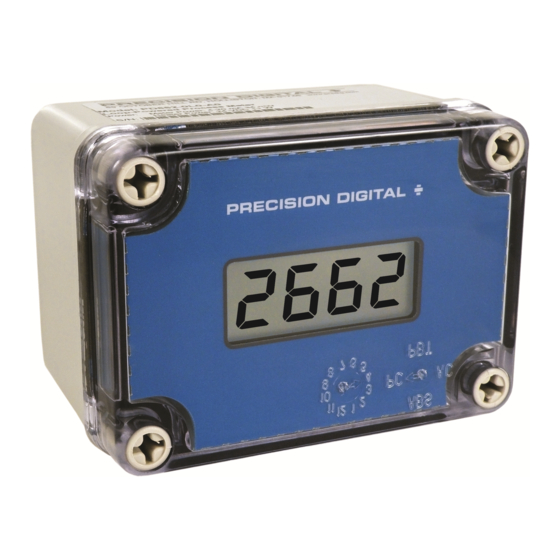
PD662 Loop-Powered Meter
4-20 mA Input Loop-Powered
-1999 to 2999 Display
Easy Four-Button Programming
NEMA 4X Enclosure
Loop-Powered Backlight Option
1.7 Volt Drop without Backlight
32-Point and Square Root Linearization Input Functions
Programmable Noise Filter
HART Protocol Transparent
CSA Certified for -40 to 75°C Operation
(-55 to 75°C with Heater Option)
PRECISION DIGITAL CORPORATION
233 South Street • Hopkinton MA 01748 USA
Tel (800) 343-1001 • Fax (508) 655-8990
Instruction Manual
C
www.predig.com
US
Advertisement
Table of Contents

Related Manuals for Precision Digital Corporation PD662 Survivor Series


Summary of Contents for Precision Digital Corporation PD662 Survivor Series
- Page 1 Programmable Noise Filter HART Protocol Transparent CSA Certified for -40 to 75°C Operation (-55 to 75°C with Heater Option) PRECISION DIGITAL CORPORATION 233 South Street • Hopkinton MA 01748 USA Tel (800) 343-1001 • Fax (508) 655-8990 www.predig.com...
- Page 2 Anyone using this product for such applications does so at his/her own risk. Precision Digital Corporation shall not be held liable for damages resulting from such improper use. Limited Warranty Precision Digital Corporation warrants this product against defects in material or workmanship for the specified period under “Specifications”...
-
Page 3: Introduction
PD662 Loop-Powered Meter Instruction Manual INTRODUCTION The PD662 NEMA 4X, CSA Certified loop-powered meter is perfect for applications where a simple, inexpensive display is required, and AC power is not available. The PD662 derives all its power from the 4-20 mA loop. -
Page 4: Table Of Contents
PD662 Loop-Powered Meter Instruction Manual Table of Contents INTRODUCTION ------------------------------------------------------------ 3 ORDERING INFORMATION --------------------------------------------- 3 SPECIFICATIONS ---------------------------------------------------------- 6 General ------------------------------------------------------------------------------- 6 Input ----------------------------------------------------------------------------------- 7 Heater --------------------------------------------------------------------------------- 7 COMPLIANCE INFORMATION ----------------------------------------- 8 Safety --------------------------------------------------------------------------------- 8 ... - Page 5 PD662 Loop-Powered Meter Instruction Manual MOUNTING DIMENSIONS ---------------------------------------------- 28 TROUBLESHOOTING ---------------------------------------------------- 30 Troubleshooting Tips --------------------------------------------------------- 30 QUICK USER INTERFACE REFERENCE GUIDE ---------------- 31 EU DECLARATION OF CONFORMITY ----------------------------- 33 Table of Figures Figure 1. PD662 Mounting Board Rear View ........11 ...
-
Page 6: Specifications
PD662 Loop-Powered Meter Instruction Manual SPECIFICATIONS Except where noted all specifications apply to operation at +25°C. General DISPLAY 0.6" (15.24 mm) LCD, 3½+ digits; -1999 to 2999 DISPLAY 2 Updates/Second UPDATE RATE OVERRANGE 2999 Display flashes UNDERRANGE -1999 Display flashes PROGRAMMING Four internal pushbuttons METHOD... -
Page 7: Input
PD662 Loop-Powered Meter Instruction Manual Input ACCURACY ±1 count FUNCTION Linear (2 to 32 points) or square root TEMPERATURE 50 PPM/C from -40 to 85C ambient DRIFT DECIMAL POINT User selectable decimal point MINIMUM SPAN Input 1 & Input 2: 0.40 mA CALIBRATION An Error message will appear if input 1 and input 2 signals RANGE... -
Page 8: Compliance Information
PD662 Loop-Powered Meter Instruction Manual COMPLIANCE INFORMATION Safety CSA CERTIFIED U.S. & Canada 2252 05 – Process Control Equipment 2252 85 – Process Control Equipment, U.S. Standards CSA FILE NUMBER 157123 CSA APPLICABLE CAN/CSA C22.2 No. 61010-1-04 Safety Requirements REQUIREMENTS for Electrical Equipment for Measurement, Control, and Laboratory Use –... -
Page 9: Safety Information
PD662 Loop-Powered Meter Instruction Manual SAFETY INFORMATION CAUTION: Read complete instructions prior to installation and operation of the meter. The equipment shall be installed by qualified personnel in accordance with applicable local and national regulations (e.g. CEC, NEC, FCC, SCC, etc). Follow all safety and operation guidelines in this manual. -
Page 10: Mounting
PD662 Loop-Powered Meter Instruction Manual Mounting The PD662 can be wall mounted using the mounting holes beneath the cover screws. A ½” NPT pipe conduit hole is provided. It can be panel mounted with the addition of the PDA6624 panel mount kit. It can also be pipe mounted by using the PDA6845 pipe mount kit. -
Page 11: Connection & Wiring Diagrams
PD662 Loop-Powered Meter Instruction Manual Refer to Figure 1 for terminal positions on the rear of the mounting board inside the meter enclosure. Meters with the heater option will also have a two terminal removable connector on the rear of the assembly. See Figure 4 for wiring details. 24 VDC power positive terminal connection 24 VDC power negative terminal connection Figure 1. -
Page 12: Figure 2. Pd662 Input Connections Without Backlight
PD662 Loop-Powered Meter Instruction Manual S+ S- X 4-20 mA Transmitter Power Supply Figure 2. PD662 Input Connections without Backlight S+ S- B- 4-20 mA Transmitter Power Supply Figure 3. PD662 Input Connections with Backlight P+ P- 24 VDC 11 W max Figure 4. -
Page 13: Setup And Programming
PD662 Loop-Powered Meter Instruction Manual SETUP AND PROGRAMMING There is no need to recalibrate the meter for milliamps when first received from the factory. The meter is factory calibrated for milliamps prior to shipment. The calibration equipment is certified to NIST standards. Overview There are no jumpers involved in the setup process of the meter. -
Page 14: Front Panel Buttons
PD662 Loop-Powered Meter Instruction Manual Front Panel Buttons ENTER MENU 2662 Button/ Description Symbol Menu button to enter programming mode. Press and hold for 5 seconds to access the Advanced features of MENU the meter. Enter button to access a menu or accept a setting. ENTER Right arrow to scroll through the menus or move to the next digit or decimal position during programming. -
Page 15: Setting Numeric Values
PD662 Loop-Powered Meter Instruction Manual Setting Numeric Values The numeric values are set using the Right and Up arrow buttons. Press Right arrow to select next digit and Up arrow to increment digit. The two left-most digits on the display are set as a single digit, able to display -19 to 29. -
Page 16: Main Menu
PD662 Loop-Powered Meter Instruction Manual Main Menu The main menu consists of the most commonly used functions: Decimal Point Location, Scale, and Calibration. Mode MENU 26. 6 2 MENU Press Menu button to enter Programming Mode then press the Up arrow button to scroll main menu. -
Page 17: Main Menu Display Functions & Messages
PD662 Loop-Powered Meter Instruction Manual Main Menu Display Functions & Messages The meter displays various functions and messages during setup, programming, and operation. The following table shows the main menu functions and messages in the order they appear in the menu. Display Parameter Action/Setting... -
Page 18: Scaling The Meter (Scl)
PD662 Loop-Powered Meter Instruction Manual Scaling the Meter (SCL) The 4-20 mA input can be scaled to display the process in engineering units. A signal source is not needed to scale the meter; simply program the inputs and corresponding display values. If using linear signal input conditioning, enter the number of scale points (2-32), followed by the input values and display values. -
Page 19: Calibrating The Meter (Cal)
PD662 Loop-Powered Meter Instruction Manual Calibrating the Meter (Cal) To scale the meter without a signal source, refer to Scaling the Meter (SCL), page 18. The meter can be calibrated to display the process in engineering units by applying the appropriate input signal. The use of a calibrated signal source is strongly recommended. -
Page 20: Advanced Features Menu
PD662 Loop-Powered Meter Instruction Manual Advanced Features Menu To simplify the setup process, functions not needed for most applications are located in the Advanced Features menu. Press and hold the MENU button for five seconds to access the Advanced Features menu Run Mode 26. -
Page 21: Advanced Features Menu & Display Messages
PD662 Loop-Powered Meter Instruction Manual Advanced Features Menu & Display Messages The following table shows the Advanced features menu functions and messages in the order they appear in the menu. Display Parameter Action/Setting Input Function Set linear or square root input conditioning function Linear Set linear scaling... -
Page 22: Signal Input Conditioning Function (Fnc)
PD662 Loop-Powered Meter Instruction Manual Signal Input Conditioning Function (Fnc) The PD662 provides linear and square root signal input conditioning functions for inputs from linear and non-linear transmitters. Linear (Lnr) Meters are set up at the factory for linear function using two-point linear- ization. -
Page 23: Internal Calibration (Ical)
PD662 Loop-Powered Meter Instruction Manual Internal Calibration (ICal) There is no need to recalibrate the meter for milliamps when first received from the factory. The meter is factory calibrated for milliamps prior to shipment. The calibration equipment is certified to NIST standards. -
Page 24: Operation
PD662 Loop-Powered Meter Instruction Manual OPERATION Front Panel Buttons Operation Button Description Symbol Press to enter or exit Programming Mode MENU or exit Max/Min readings Press to reset Max/Min readings Press to display Max/Min readings alternately Press to display Max or Min reading ENTER indefinitely while displaying Max or Min... -
Page 25: Maximum & Minimum Readings (Hi & Lo)
PD662 Loop-Powered Meter Instruction Manual Maximum & Minimum Readings (HI & LO) The maximum and minimum (peak & valley) readings reached by the process are stored in the meter since the last reset or power-up. The meter flashes HI or LO to differentiate between run mode and max/min display. -
Page 26: Reset Meter To Factory Defaults
PD662 Loop-Powered Meter Instruction Manual Reset Meter to Factory Defaults When the parameters have been changed in a way that is difficult to determine what’s happening, it might be better to start the setup process from the factory defaults. Instructions to load factory defaults: Enter the Advanced features menu. -
Page 27: Factory Defaults & User Settings
PD662 Loop-Powered Meter Instruction Manual Factory Defaults & User Settings The following table shows the factory setting for most of the programmable parameters on the meter. Next to the factory setting, the user may record the new setting for the particular application. Model: ______________ S/N: _______________ Date: _________ Parameter... -
Page 28: Mounting Dimensions
PD662 Loop-Powered Meter Instruction Manual MOUNTING DIMENSIONS Figure 5. Case Dimensions – Front View Figure 6. Case Dimensions – Side View A: 3.15 in (80 mm) B: 4.33 in (110 mm) C: 2.44 in (62 mm) E: 2.76 in (70 mm) D: 3.62 in (92 mm) 3.35 in (85 mm) with heater option F: 0.79 in (20 mm);... -
Page 29: Figure 7. Case Dimensions - Bottom View
PD662 Loop-Powered Meter Instruction Manual Figure 7. Case Dimensions – Bottom View G: 0.87 in (22 mm) H: 0.80 in (20 mm) I: 2.17 in (55 mm) Figure 8. PDA6845 Pipe Mounting Kit The PDA6845 pipe mounting kit may be used to mount a PD662 to a 2” pipe. -
Page 30: Troubleshooting
PD662 Loop-Powered Meter Instruction Manual TROUBLESHOOTING Due to the many features and functions of the meter, it’s possible that the setup of the meter does not agree with what an operator expects to see. If the meter is not working as expected, refer to the recommendations described below. -
Page 31: Quick User Interface Reference Guide
PD662 Loop-Powered Meter Instruction Manual QUICK USER INTERFACE REFERENCE GUIDE Pushbutton Function Menu Go to Programming Mode, leave Programming Mode, and Max/Min Mode. Hold for 5 seconds to access Advanced Features. Right Arrow Move to next digit or decimal point position. Reset Min/Max. Up Arrow Move to next selection or increment digit. - Page 32 PD662 Loop-Powered Meter Instruction Manual This Page Intentionally Left Blank...
-
Page 33: Eu Declaration Of Conformity
EN 61010-1:2010, and EN 61326:2013 and there were no major technical changes af- fecting the latest technical knowledge for the products listed above. Product Markings: Signed for and on behalf of Precision Digital Corporation: Name: Jeffrey Peters Company:... - Page 34 PD662 Loop-Powered Meter Instruction Manual How to Contact Precision Digital For Technical Support: Call: (800) 610-5239 or (508) 655-7300 Fax: (508) 655-8990 Email: support@predig.com For Sales Support: Call: (800) 343-1001 or (508) 655-7300 Fax: (508) 655-8990 For the latest version of this manual please visit: www.predig.com LIM662_H SFT054 Ver 1.800 &...
Need help?
Do you have a question about the PD662 Survivor Series and is the answer not in the manual?
Questions and answers