Table of Contents
Advertisement
Quick Links
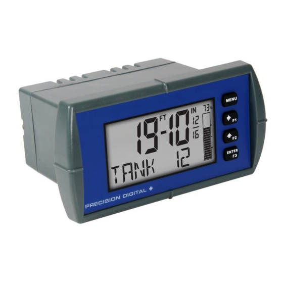
PD6603 & PD6607 Loop-Powered Feet & Inches Meter
Instruction Manual
•
1/8 DIN Loop-Powered Feet & Inches Meter with NEMA 4X, IP65 Front
•
4-20 mA Input Displayed with ±0.02% FS Accuracy
•
1.5 Volt Drop (4.5 Volt Drop with Backlight)
•
0.7" (17.8 mm) 5 Digits 7-Segment, FT-IN & Fractions, Top Display
•
0.4" (10.2 mm) 8 Alphanumeric Characters Bottom Display
•
Displays Level in Feet & Inches up to 999 Feet, 11 & 15/16 Inches
•
Display Input in Two Different Scales Simultaneously - Great for Level
•
20-Segment Bargraph with Numeric Percent Indication
•
Shallow Depth Case Extends Only 3.6" (91 mm) Behind Panel
•
(2) Open Collector Outputs Standard; Assigned to Pulse, Alarm, Timer, or Stopwatch
•
(2) Optional Loop-Powered Solid State Relays; Assigned to Alarm, Control, Timer, or Stopwatch
•
Stopwatch & Timer Functions to Drive Relays & Open Collectors
•
Optional Isolated 4-20 mA Analog Output
•
Relay Pump Alternation Based on Level and Runtime
•
Display Relay Runtime & Cycle Count via Relay Info Menu
•
Round Horizontal Tank Function; Just Enter Diameter & Length
•
32-Point Linearization
•
Free PC-Based MeterView XL USB Programming Software
•
®
HART
Protocol Transparent
•
Loop-Powered Backlight with Red Backlight for Alarm Conditions
•
Safe Area Operating Temperature Range: -40 to 167°F (-40 to 75°C)
•
Conformal Coated PCBs for Dust & Humidity Protection
•
Password Protection
•
UL & C-UL 61010 Listed for Electrical Safety
•
UL & C-UL Listed as Intrinsically Safe and Nonincendive
•
ATEX and IECEx Certified as Intrinsically Safe
•
Wide Assortment of NEMA 4X Enclosures for up to Ten Meters
•
Light / Horn & Reset Button Accessory
•
Control Station Accessory for Remote Operation of Digital Input
•
3-Year Warranty
PRECISION DIGITAL CORPORATION
233 South Street • Hopkinton MA 01748 USA
Tel (800) 343-1001 • Fax (508) 655-8990
www.predig.com
IECEx
All Models
PD6607 Only
Advertisement
Table of Contents

Subscribe to Our Youtube Channel
Related Manuals for Precision Digital Corporation Loop Leader Series


Summary of Contents for Precision Digital Corporation Loop Leader Series
- Page 1 • Light / Horn & Reset Button Accessory • Control Station Accessory for Remote Operation of Digital Input • 3-Year Warranty PRECISION DIGITAL CORPORATION 233 South Street • Hopkinton MA 01748 USA Tel (800) 343-1001 • Fax (508) 655-8990 www.predig.com...
-
Page 2: Table Of Contents
PD6603 & PD6607 Loop-Powered Feet & Inches Meter Instruction Manual Table of Contents Introduction ......................4 Key Features ....................... 5 Ordering Information ..................8 General Purpose Instruments ............... 8 Hazardous Area Instruments ................ 8 Enclosures ...................... 8 Accessories ....................8 Specifications .................... - Page 3 PD6603 & PD6607 Loop-Powered Feet & Inches Meter Instruction Manual Setting the Display Features (DISPLAY) ............ 29 Changing the Engineering Units (UNITS) ..........29 Changing the Decimal Point (DEC. P T) ............29 Enabling or Disabling Commas on the Bottom Display (COMMA) ....29 Display Capabilities Optimization (BOTTOM) ..........
-
Page 4: Introduction
Limited Warranty ous areas. Precision Digital Corporation warrants this product against defects in material or workmanship for the Free, PC-based, MeterView XL software that con- specified period under “Specifications” from the nects to the meter via a micro USB cable is available date of shipment from the factory. -
Page 5: Key Features
PD6603 & PD6607 Loop-Powered Feet & Inches Meter Instruction Manual Key Features Informative Display Feet & Inches Display with The Loop Leader’s display provides multiple ways Bargraph to help users understand and keep track of their The PD6603/07 Loop Leader meter is designed for processes. - Page 6 PD6603 & PD6607 Loop-Powered Feet & Inches Meter Instruction Manual The following graphics provide a visual representation Predefined and Custom Units of a typical pump alternation application: The meter has six available preprogrammed unit classes: volume, height, temperature, pressure, weight, and rate. When the desired unit class or unit of measure within a class is not available, a custom unit may be programmed.
- Page 7 PD6603 & PD6607 Loop-Powered Feet & Inches Meter Instruction Manual Round Horizontal Tank Input Signal Conditioning Linearization (RH TANK) Functions (FUNCTION) This function automatically calculates the volume in a The Function menu is used to select the input signal round horizontal tank with flat ends. It is only available conditioner applied to the input: linear or round hori- for PV2 while the meter is in dual-scale mode.
-
Page 8: Ordering Information
PD6603 & PD6607 Loop-Powered Feet & Inches Meter Instruction Manual Ordering Information General Purpose Instruments Loop Leader PD6603 • Feet & Inches Models – General Purpose Model Description PD6603–LNN Loop-Powered, General Purpose, Feet & Inches, No Options PD6603–L2N Loop-Powered, General Purpose, Feet & Inches, Two Solid State Relays PD6603–L3N Loop-Powered, General Purpose, Feet &... - Page 9 PD6603 & PD6607 Loop-Powered Feet & Inches Meter Instruction Manual PDA2360 Plastic Control Stations Signal Splitter & Conditioner Accessories Model Description Model Description Signal Isolator with One 4-20 mA PDA2360-E Emergency Button PD659-1MA-1MA Input and One 4-20 mA Output PDA2361-A Ack Button Signal Splitter with One 4-20 mA PDA2361-B...
- Page 10 PD6603 & PD6607 Loop-Powered Feet & Inches Meter Instruction Manual Useful Tools PD9501 Multi-Function Calibrator This PD9501 Multi-Function Calibrator has a variety of signal measurement and output functions, including voltage, current, thermocouple, and RTD. PD9502 Low-Cost Signal Generator PD9502 is a low-cost, compact, simple to use 4-20 mA or 0-10 VDC signal generator.
-
Page 11: Specifications
PD6603 & PD6607 Loop-Powered Feet & Inches Meter Instruction Manual Specifications Noise Filter Averages the input signal over a period of time between 1 and 16 seconds to dampen the effects of a noisy signal that causes a Except where noted all specifications apply to operation at +25°C. jumpy display. -
Page 12: Common Open Collector & Relay (Alarm) Specifications
PD6603 & PD6607 Loop-Powered Feet & Inches Meter Instruction Manual Common Open Collector & Solid State Relays Relay (Alarm) Specifications Rating 250 VAC/VDC @ 1A resistive 75VA; 250VAC; 0.6A pilot duty (induc- Number Two open collectors & two relays tive) – UL Code D300 25VA;... -
Page 13: Meterview Xl Programming Software
PD6603 & PD6607 Loop-Powered Feet & Inches Meter Instruction Manual General Compliance MeterView XL Programming Software Information Availability Free download from www.predig.com Electromagnetic Compatibility System Microsoft® Windows® 7 & 10 Requirements EMC Emissions • CFR 47 FCC Part 15 Subpart B Communications USB 2.0 Class A emissions requirements (Standard USB A to Micro USB B) -
Page 14: Pd6607 Compliance Information
PD6603 & PD6607 Loop-Powered Feet & Inches Meter Instruction Manual PD6607 Compliance ATEX/IECEx Special Conditions for Safe Use The following conditions relate to safe installation Information and/or use of the equipment. • The permitted ambient temperature range for the Safety PD6607 is -40°C to 70°C. -
Page 15: Eu Declaration Of Conformity
PD6603 & PD6607 Loop-Powered Feet & Inches Meter Instruction Manual EU Declaration of Conformity Required I.S. Equipment EU Declaration of Conformity for the PD6603 and Relationship I.S. Barrier Entity Entity Between Entity Parameters PD6607 are available in the Documentation CD Parameters Parameters provided with the product under the EU DoC menu. -
Page 16: Installation
PD6603 & PD6607 Loop-Powered Feet & Inches Meter Instruction Manual Installation There is no need to remove the meter from its case to complete the installation, wiring, and setup of the me- ter for most applications. • PD6607 installation must be performed in accordance with Control Drawing LIM6600-2 in order to meet agency approval ratings. -
Page 17: Meterview Xl Programming Software
PD6603 & PD6607 Loop-Powered Feet & Inches Meter Instruction Manual 4. Double-click MeterView XL Windows Installer MeterView XL Programming Package file to open: Software Free, PC-based, MeterView XL software that connects to the meter via a USB cable is available for program- 5. -
Page 18: Connecting To The Computer
Loop Leader meter. to confirm the installation: Connecting to the Computer Loop Leader series meters may be connected to any Windows 7 or Windows 10 PC via the provided USB cable by following these steps: Open the MeterView XL software. -
Page 19: Dimensions
PD6603 & PD6607 Loop-Powered Feet & Inches Meter Instruction Manual Dimensions Connections All connections are made to removable screw All units: inches (mm) terminal connectors located at the rear of the meter. 1.76" (45mm) This section is only intended for PD6603 safe area installations. -
Page 20: Wiring Diagrams
PD6603 & PD6607 Loop-Powered Feet & Inches Meter Instruction Manual Wiring Diagrams Safe Area 4-20 mA Output Connections Connections for the 4-20 mA transmitter output are Safe Area Current Loop (4-20 mA) made to the connector terminals labeled mA OUT. The 4-20 mA output must be powered from an exter- Connections nal power supply. -
Page 21: Remote Operation Of Meter
PD6603 & PD6607 Loop-Powered Feet & Inches Meter Instruction Manual Wiring Connections for MOD-LH Models Remote Operation of Meter The following diagram is for MOD-LH models with a The meter is equipped with a digital input that can be single color light. programmed to perform various functions. -
Page 22: Setup And Programming
PD6603 & PD6607 Loop-Powered Feet & Inches Meter Instruction Manual Setup and Programming Front Panel Buttons and Status LCD Indicators The meter is factory calibrated prior to shipment to display 0 to 100, which corresponds to the 4-20 mA input. The calibration equipment is traceable to NIST standards. -
Page 23: Display Functions & Messages
PD6603 & PD6607 Loop-Powered Feet & Inches Meter Instruction Manual Display Functions & Messages Parameter Action/Setting Description DISABLE Disable the relay The meter displays various functions and messages during setup, programming, and operation. The following table ALARM Program relay for alarm shows the main menu functions and messages in the order functionality they appear in the menu. - Page 24 PD6603 & PD6607 Loop-Powered Feet & Inches Meter Instruction Manual Parameter Action/Setting Description Parameter Action/Setting Description CAL PV STOP. A LL Stop all timers Calibrate the input (1 or 2) S. S TP. A LL Start or stop all timers CUTOFF Set low-flow cutoff Start/stop open collector 1 timer...
- Page 25 PD6603 & PD6607 Loop-Powered Feet & Inches Meter Instruction Manual Parameter Action/Setting Description Parameter Action/Setting Description DISABLE Turn the hint function off Disable bargraph BOTTOM Turn the hint function on Select what to display on the bottom line SYSTEM Program system settings Display the tag (default) AOUTCAL Calibrate the analog output...
-
Page 26: Main Menu
PD6603 & PD6607 Loop-Powered Feet & Inches Meter Instruction Manual Setting Numeric Values Main Menu The numeric values are set using the Right and The main menu consists of all the meter’s programma- Up-Arrow buttons. ble functions: Input, Output, Advanced, and Display. Press Right-Arrow to select next digit and •... -
Page 27: Available Unit Classes And Units
PD6603 & PD6607 Loop-Powered Feet & Inches Meter Instruction Manual Available Unit Classes and Units The process variable (PV) can be scaled in several Pressure Units (PRESSURE) different height units. No matter the scaling units, the Pounds per inch scaled value will be converted to feet & inches for dis- InHg Inches of mercury play. -
Page 28: Setting Custom Units (Custom)
PD6603 & PD6607 Loop-Powered Feet & Inches Meter Instruction Manual Scaling Example Setting Custom Units (CUSTOM) When the desired unit class or unit of measure within The 4-20 mA input can be scaled to the appropriate a class for PV 2 is not available, a custom unit may be values for a given application. -
Page 29: Setting The Display Features (Display)
PD6603 & PD6607 Loop-Powered Feet & Inches Meter Instruction Manual Enabling or Disabling Commas on the Setting the Display Features Bottom Display (COMMA) (DISPLAY) The bottom display is set to show a comma separat- The meter’s display functions may be programmed ing the thousands and millions place by default if a numeric value is being displayed. -
Page 30: Configuring The Display (Bottom)
PD6603 & PD6607 Loop-Powered Feet & Inches Meter Instruction Manual Programming the Bargraph (BARGRAPH) Configuring the Display (BOTTOM) The meter comes equipped with a bargraph display The bottom display line (BOTTOM) can be pro- for applications where a visual representation of the grammed to display different values. -
Page 31: Programming The Outputs (Output)
PD6603 & PD6607 Loop-Powered Feet & Inches Meter Instruction Manual The Open Collector Outputs are programmed in the Programming the Outputs following manner: (OUTPUT) Depending on the purchased model, the meter may OUTPUT be available with two open collector outputs, two solid state relays, and one 4-20 mA output. - Page 32 PD6603 & PD6607 Loop-Powered Feet & Inches Meter Instruction Manual Alarm (ALARM) Alarm outputs may be assigned to the PV or the digital input. When assigned to the PV, the alarm may be set as either a high alarm or a low alarm. Alarm actions (AUTO, AUTO.
- Page 33 PD6603 & PD6607 Loop-Powered Feet & Inches Meter Instruction Manual Timer (TIMER) Stopwatch (STPWATCH) The timer output may be set to generate the timed The stopwatch function may be used to manually run pulse only once (ONESHOT) or continuously (CONT). and control a process for a specific time interval up to 99 hrs., 59 min, and 59 seconds.
-
Page 34: Solid State Relay Outputs (Relay)
PD6603 & PD6607 Loop-Powered Feet & Inches Meter Instruction Manual Solid State Relay Outputs (RELAY) Alarm (ALARM) The meter can be optionally equipped with two solid Alarm outputs may be assigned to the PV or the digi- state relays that may be set up for alarms, timer, tal input. - Page 35 PD6603 & PD6607 Loop-Powered Feet & Inches Meter Instruction Manual Pump Control (PUMPCTRL) Pump Alternation (ALTERN) The pump control output is used in situations where Pump alternation sets the two relays to alternate the relays are used to control pumps. There are two every time the first on point (ON 1) is reached.
- Page 36 PD6603 & PD6607 Loop-Powered Feet & Inches Meter Instruction Manual Pump Alternation Example Timer (TIMER) The following is an example application where the re- The timer output may be set to generate the timed lays are programmed for pump alternation. pulse only once (ONESHOT) or continuously (CONT).
-
Page 37: Isolated 4-20 Ma Output (4-20 Ma)
PD6603 & PD6607 Loop-Powered Feet & Inches Meter Instruction Manual Isolated 4-20 mA Output (4-20 mA) Stopwatch (STPWATCH) The 4-20 mA menu is used to scale the isolated 4-20 The stopwatch function may be used to manually run mA output based on display values. This menu is not and control a process for a specific time interval up to present on models without a 4-20 mA output option. -
Page 38: Advanced Features Menu (Advanced)
PD6603 & PD6607 Loop-Powered Feet & Inches Meter Instruction Manual Advanced Process Variable Setup Advanced Features Menu (ADV PV SETUP) (ADVANCED) The Advanced PV Setup menu contains options to apply input signal conditioning functions to the input To simplify the setup process, functions not needed and scale/calibrate the input signal. - Page 39 PD6603 & PD6607 Loop-Powered Feet & Inches Meter Instruction Manual Multi-Point Linearization Round Horizontal Tank Linearization (RH TANK) (LINEAR) Meters are set up at the factory for linear function with This function automatically calculates the volume in a 2-point linearization. Up to 32 linearization points can round horizontal tank with flat ends.
-
Page 40: Low-Height Cutoff (Cutoff)
PD6603 & PD6607 Loop-Powered Feet & Inches Meter Instruction Manual Follow these steps to calibrate the input: Advanced Scaling and Calibration (SCALE. C AL) After accessing the SCALE. C AL menu, press the Right-Arrow button to scroll to the This menu offers options to scale or calibrate the Calibration menu (CAL PV) and press Enter. -
Page 41: Enabling Password Protection (Passwrd)
PD6603 & PD6607 Loop-Powered Feet & Inches Meter Instruction Manual Enabling Password Protection Programmable Function Keys User Menu (PASSWRD) (USER) The User menu allows the user to assign the front The Password menu is used for programming security panel function keys F1, F2, and F3, and the digital to prevent unauthorized changes to the programmed input (located on the input signal connector) to access parameter settings. - Page 42 PD6603 & PD6607 Loop-Powered Feet & Inches Meter Instruction Manual Function Keys & Digital Input Display Description Available Settings TARE. F N Set the function key or digital input to tare the display value Refer to the following table for descriptions of each TARE Tare the display value available function key or digital input setting.
-
Page 43: Changing System Settings (System)
PD6603 & PD6607 Loop-Powered Feet & Inches Meter Instruction Manual Enabling the Function Key Hint Enabling the Dual-Scale Feature Feature (HINT) (PV2) Enabling the function key hint feature will cause a hint message to be displayed when pressing the F1, F2, or F3 function keys. - Page 44 PD6603 & PD6607 Loop-Powered Feet & Inches Meter Instruction Manual Calibrating the Internal mA The Internal Calibration menu is part of the Advanced menu. Internal Calibration is performed as follows: Reference (ICAL) Press the Menu button to enter Programming Mode. The meter is factory calibrated prior to shipment to display Press the Up-Arrow button twice and press 0 to 100, which corresponds to the 4-20 mA input.
-
Page 45: Meter Operation
PD6603 & PD6607 Loop-Powered Feet & Inches Meter Instruction Manual Meter Operation Digital Input Operation The meter can accept a 4-20 mA current signal and A digital input is standard on the meter. This digital display it in feet and inches from -99 ft 11 in 15/16 to input is programmed identically to function keys F1, 999 ft 11 in 15/16 on the top line or from -9,999,999 to F2, and F3. -
Page 46: Runtime & Cycle Count (Info)
PD6603 & PD6607 Loop-Powered Feet & Inches Meter Instruction Manual Runtime & Cycle Count (INFO) The relay information menu shows runtime and cycle count for each relay. These values may be cleared at any time by selecting the Clear option (CLEAR?). If the cycle count or runtime values need to be changed on a frequent basis, it would be convenient to set up a front panel button or the digital input to simplify this... -
Page 47: Troubleshooting
PD6603 & PD6607 Loop-Powered Feet & Inches Meter Instruction Manual Troubleshooting Determining Software Version This product is a highly sophisticated instrument with To determine the software (firmware) version of a an extensive list of features and capabilities. If the meter: front panel buttons are used to program the meter, it Press the Menu button to enter can be a difficult task to keep everything straight. -
Page 48: Factory Default Settings
PD6603 & PD6607 Loop-Powered Feet & Inches Meter Instruction Manual Factory Default Settings Parameter Display Default Setting The following table shows the factory setting for most MSG EDIT Message Text ALARM 3 of the programmable parameters on the meter. Pump Ctrl On 70.00 Parameter Display... -
Page 49: Troubleshooting Tips
PD6603 & PD6607 Loop-Powered Feet & Inches Meter Instruction Manual Troubleshooting Tips Certain sequences of events can cause unexpected results. To solve these issues, it is best to start fresh from factory defaults and use the manual as a step by step programming guide, rather than a random approach to programming. See Reset Meter to Factory Defaults on page 47 for details on resetting the meter to factory defaults. - Page 50 Email: sales@predig.com Place Orders Email: orders@predig.com For the latest version of this manual please visit www.predig.com PRECISION DIGITAL CORPORATION 233 South Street • Hopkinton MA 01748 USA Tel (800) 343-1001 • Fax (508) 655-8990 www.predig.com LIM6603_I SFT124 Ver 2.000 & up...
Need help?
Do you have a question about the Loop Leader Series and is the answer not in the manual?
Questions and answers