Precision Digital Corporation Survivor PD662 Instruction Manual
Field-mount loop-powered process meter
Hide thumbs
Also See for Survivor PD662:
- Instruction manual (18 pages) ,
- Instruction manual (34 pages) ,
- Quick start manual (2 pages)
Table of Contents
Advertisement
Quick Links
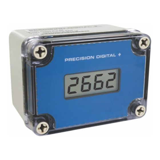
PD662 Field-Mount Loop-Powered Process Meter
Instruction Manual
• NEMA 4X, IP66 Loop-Powered Field-Mount Process Meter
• 4-20 mA Input
• 1.7 Volt Drop (3.7 Volt Drop with Backlight)
• Easy Field Scaling in Engineering Units without Applying an Input
• 0.6" (15.2 mm) 3½+ Digits LCD Display; -1999 to 2999
• HART
Protocol Transparent
®
• Loop-Powered Backlight Option
• CSA Certified Operating Temperature Range: -40 to 75°C (-40 to 167°F)
• Four Internal Buttons for Easy Field Scaling
• Max/Min Display
• Programmable Noise Filter
• 32-Point Linearization & Square Root Extraction
• Conformal Coated PCBs for Dust and Humidity Protection
• One 1/2" Conduit Hole in Enclosure
• Pipe & Panel Mounting Kits Available
• Stainless Steel Tag Available
• 3-Year Warranty
PRECISION DIGITAL CORPORATION
233 South Street • Hopkinton MA 01748 USA
Tel (800) 343-1001 • Fax (508) 655-8990
www.predig.com
C
US
Advertisement
Table of Contents

Subscribe to Our Youtube Channel
Related Manuals for Precision Digital Corporation Survivor PD662


Summary of Contents for Precision Digital Corporation Survivor PD662
- Page 1 • One 1/2" Conduit Hole in Enclosure • Pipe & Panel Mounting Kits Available • Stainless Steel Tag Available • 3-Year Warranty PRECISION DIGITAL CORPORATION 233 South Street • Hopkinton MA 01748 USA Tel (800) 343-1001 • Fax (508) 655-8990 www.predig.com...
-
Page 2: Introduction
Limited Warranty Steel; (1) 13 Gauge Mounting Plate, (2 each) Bolts, Washers, Lock Washers & Precision Digital Corporation warrants this PDA6845 Nuts to Mount Meter to Plate, (1) U-Bolt product against defects in material or and (2 each) Washers, Lock Washers &... -
Page 3: Accessories
PD662 Field-Mount Loop-Powered Process Meter Instruction Manual Accessories PDA6624 Panel Mounting Kit PDA1024-01 24 VDC Power Supply PDA6624 Panel Mounting Kit provides a conven- ient way to mount Precision Digital’s model PD662 in a panel. All the necessary hardware is provided, and PDA1024-01 is a DIN rail mounted 1.5 A, installation is a quick and easy process. -
Page 4: Table Of Contents
PD662 Field-Mount Loop-Powered Process Meter Instruction Manual Table of Contents Introduction ......................2 Ordering Information ..................2 Accessories ......................3 Useful Tools ......................3 Specifications ..................... 6 General ......................6 Input ........................ 6 Compliance Information..................6 Safety ......................6 Electromagnetic Compatibility ..............6 Safety Information .................. - Page 5 PD662 Field-Mount Loop-Powered Process Meter Instruction Manual Table of Figures Figure 1. Case Dimensions – Front View............8 Figure 2. Case Dimensions – Side View ............. 8 Figure 3. Case Dimensions – Bottom View ............8 Figure 4. Location of Captive Screws and Programming Buttons ....10 Figure 5.
-
Page 6: Specifications
PD662 Field-Mount Loop-Powered Process Meter Instruction Manual Specifications Input Except where noted all specifications apply to operation at +25°C. Input 4-20 mA General Accuracy ±1 count Maximum Without With Loop-Powered Display 0.6" (15.2 mm) LCD, 3½+ digits; -1999 to 2999 Voltage Drop &... -
Page 7: Safety Information
PD662 Field-Mount Loop-Powered Process Meter Instruction Manual Safety Information PDA-SSTAG Stainless Steel Tag • The equipment shall be installed by qualified personnel in accordance with applicable local and national regulations (e.g. CEC, NEC, FCC, SCC, etc). Follow all safety and operation guidelines in this •... -
Page 8: Installation
PD662 Field-Mount Loop-Powered Process Meter Instruction Manual Installation Dimensions All pushbuttons and wiring connectors are accessed by opening the NEMA 4X enclosure by removing the four captive screws that secure the cover. The four holes to mount the PD662 to either a wall or the pipe-mounting kit are accessed by removing the four captive screws that secure the cover. -
Page 9: Mounting
PD662 Field-Mount Loop-Powered Process Meter Instruction Manual Mounting PDA6624 Panel Mounting Kit The PD662 can be wall-mounted, panel-mounted, or attached to a 1.5" or 2" pipe. A ½" NPT pipe conduit hole is provided for bringing in field wiring. The PD662 is wall-mounted using the mounting holes beneath the cover screws. -
Page 10: Connections
PD662 Field-Mount Loop-Powered Process Meter Instruction Manual Connections Wiring Diagrams To access the wiring connector, remove the enclosure Input Signal connections are made to a three-terminal cover and unscrew the two captive thumb-screws on connector labeled S+|S-|X for models without a back- the standoff mounting board. -
Page 11: Setup And Programming
PD662 Field-Mount Loop-Powered Process Meter Instruction Manual Setup and Programming Setting Numeric Values The numeric values are set using the Right and Up arrow buttons. Press Right arrow to select next digit • There is no need to recalibrate the meter for and Up arrow to increment digit. -
Page 12: Main Menu Display Functions & Messages
PD662 Field-Mount Loop-Powered Process Meter Instruction Manual Main Menu Display Functions & Setting the Decimal Point (dP) Messages A decimal point may be set in any of three positions: 1.999, 19.99, 199.9. It may also be turned off: 1999 The meter displays various functions and messages during setup, programming, and operation. -
Page 13: Scaling The Meter (Scl)
PD662 Field-Mount Loop-Powered Process Meter Instruction Manual Scaling the Meter (SCL) Calibrating the Meter (Cal) The 4-20 mA input can be scaled to display the The meter can be calibrated to display the process in process in engineering units. engineering units by applying the appropriate input signals. -
Page 14: Advanced Features Menu
PD662 Field-Mount Loop-Powered Process Meter Instruction Manual Advanced Features Menu Input Signal Conditioning Function (Fnc) To simplify the setup process, functions not needed for most applications are located in the Advanced The PD662 provides linear (from 2 to 32 points) and Features menu. -
Page 15: Internal Calibration (Ical)
PD662 Field-Mount Loop-Powered Process Meter Instruction Manual Operation Internal Calibration (ICal) Front Panel Buttons Operation • There is no need to recalibrate the meter for milliamps when first received from the factory. Button Symbol Description • The meter is factory calibrated for milliamps prior to shipment. -
Page 16: Maximum & Minimum Readings (Hi & Lo)
PD662 Field-Mount Loop-Powered Process Meter Instruction Manual Maximum & Minimum Readings Reset Meter to Factory Defaults (HI & LO) If the meter has inadvertently been programmed to behave in some undesirable manner, the best course The maximum and minimum (peak & valley) readings of action might be to reset the meter to factory de- reached by the process are stored in the meter since faults and re-program it from scratch. -
Page 17: Factory Default & User Settings
PD662 Field-Mount Loop-Powered Process Meter Instruction Manual Factory Default & User Settings Troubleshooting Due to the many features and functions of the meter, The following table shows the factory setting for most it’s possible that the setup of the meter does not of the programmable parameters on the meter. -
Page 18: Quick User Interface Reference Guide
PD662 Field-Mount Loop-Powered Process Meter Instruction Manual Quick User Interface Reference Guide Pushbutton Function Menu Go to Programming Mode, leave Programming Mode, and Max/Min Mode. Hold for 5 seconds to access Advanced Features. Right Arrow Move to next digit or decimal point position. Reset Min/Max. Up Arrow Move to next selection or increment digit. -
Page 19: Eu Declaration Of Conformity
EN 61010-1:2010+A1:2019 and EN 61326-1:2021 and there were no major technical changes affecting the latest technical knowledge for the products listed above. Product Markings: Signed for and on behalf of Precision Digital Corporation: Name: Jeffrey Peters Company: Precision Digital Corporation... - Page 20 Email: sales@predig.com Place Orders Email: orders@predig.com For the latest version of this manual please visit www.predig.com PRECISION DIGITAL CORPORATION 233 South Street • Hopkinton MA 01748 USA Tel (800) 343-1001 • Fax (508) 655-8990 www.predig.com LIM662_J SFT054 Ver 1.800 & up...
Need help?
Do you have a question about the Survivor PD662 and is the answer not in the manual?
Questions and answers