
Subscribe to Our Youtube Channel
Related Manuals for Leuze electronic GS 754B


Summary of Contents for Leuze electronic GS 754B
- Page 1 GS 754B CCD Forked Photoelectric Sensors O r i g in a l op e r a ti n g i n s tr uc t i o ns...
- Page 2 © 2017 Leuze electronic GmbH + Co. KG In der Braike 1 D-73277 Owen / Germany Phone: +49 7021 573-0 Fax: +49 7021 573-199 http://www.leuze.com info@leuze.com Leuze electronic GS 754B...
-
Page 3: Table Of Contents
Configuration table for GS 754B........ - Page 4 Configuration cable ............33 Declaration of conformity ....... 34 GS 754B Leuze electronic...
-
Page 5: About This Document
About this document About this document This technical description contains information regarding the proper use of the GS 754B measuring CCD forked photoelectric sensors. Explanation of symbols The symbols used in this technical description are explained below. Attention This symbol precedes text messages which must strictly be observed. Failure to comply with this information results in injuries to personnel or damage to the equipment. -
Page 6: Safety
This sensor was developed, manufactured and tested in line with the applicable safety stan- dards. It corresponds to the state of the art. Intended use In connection with a connected control system or evaluation unit, GS 754B CCD forked photoelectric sensors are used to detect and measure small objects in industrial production processes. -
Page 7: Foreseeable Misuse
The device must not be tampered with and must not be changed in any way. The device must not be opened. There are no user-serviceable parts inside. Repairs must only be performed by Leuze electronic GmbH + Co. KG. Competent persons Connection, mounting, commissioning and adjustment of the device must only be carried out by competent persons. -
Page 8: Disclaimer
Safety Disclaimer Leuze electronic GmbH + Co. KG is not liable in the following cases: • The device is not being used properly. • Reasonably foreseeable misuse is not taken into account. • Mounting and electrical connection are not properly performed. -
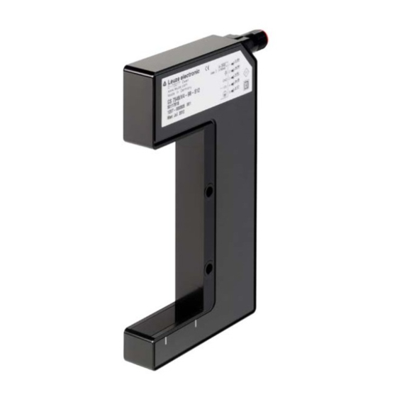
Page 9: Controls And Indicators
Controls and indicators Controls and indicators Interface P LED indicators Measurement range Figure 3.1: Positioning of the controls and indicators Leuze electronic GS 754B... -
Page 10: Device Description
• The analog interface can only output one measurement value at a time. • The digital interface can transmit any number of measurement values. Optical data GS 754B Output modes 1 … 5 Output mode 7 (default) Measurement range 25mm... -
Page 11: Led Indicators
Device description LED indicators Meaning green, continuous light Ready green, flashing Interference Table 4.2: LED indicators Leuze electronic GS 754B... -
Page 12: Applications
Depending on which interface is used, data for up to three objects can be output. Data for more than one object can only be transmitted via the serial interface. The analog value is always based on the edge or diameter information. Figure 5.1: Diameter determination application example GS 754B Leuze electronic... -
Page 13: Ascii Representation Via Rs 232 (P And M12 Interfaces)
Binary representation via RS 232 (P and M12 interfaces) Due to the fast output of measurement values, only data for single-object detection can be output in this output mode. The measurement values cannot be displayed on the screen (see chapter 7.2.2). Leuze electronic GS 754B... -
Page 14: Edge Measurement And Height Verification
Various configurations are possible with this measurement (see chapter 6.4). The following only applies to devices with an analog interface: Linear edge measurement over the entire measuring range (s. point 8) Teach-in edge measurement with 5V-output at teaching point GS 754B Leuze electronic... -
Page 15: Width Measurement
Applications Width measurement To measure the width of strip material, two GS 754B CCD forked photoelectric sensors can be used mutually opposed from one another. Figure 5.5: Width measurement Each forked photoelectric sensor relays an edge position which can be extrapolated to the total width when the distance of the sensors vis-à-vis one another is known in the control. -
Page 16: Device Configuration
Device configuration General information To configure the GS 754B forked photoelectric sensor, you require a PC with an RS 232 interface and a terminal program with the following setting. For this, use the corresponding KB-ODS 96-1500 cable (part no. 50082007). -
Page 17: Configuration Of The Measurement, Analysis And Output Procedures Over Interface P
Configuration of the measurement, analysis and output procedures over interface P The appropriate configuration is activated by entering ASCII characters. Letters may be entered in either capital or lowercase form. 6.3.1 Configuration table for GS 754B ASCII commands Available for interface Output mode Object type "!"... - Page 18 PNP switching level; refer to the following note. Table 6.2: Parameterizing commands GS 754B By entering the ASCII character "R", the state on delivery is restored. "R", however, has no effect on the configuration of the switching function and the switching level.
-
Page 19: Special Configurations
In this configuration the number of edges is not checked. Error messages are not output. Transmitter Edge Figure 6.1: Edge measurement for perforated objects Required ASCII commands: Object number single-object measurement (default) Evaluation process edge detection (default) Object type perforated objects Leuze electronic GS 754B... -
Page 20: Changeover Of The Edge Assignment For Single-Object Measurement
Edge, inside Figure 6.2: Changeover of the edge assignment for single-object measurement ASCII commands for changing over the edge assignment: Edge assignment for analog output (single-object measurement) object diameter edge, middle edge, inside (default) edge, outside GS 754B Leuze electronic... -
Page 21: Pin 2 As A Teach Input
Transmitter 13,9 mA [6,7 V] 10 mA Teach-point [5 V] 0,0 mA 25.3 mm [0,04 V] 20.0 mm 6,75 mm 20,0 mm 25,3 mm Figure 6.4: Teach-in (edge at the end of the measurement field) Leuze electronic GS 754B... -
Page 22: Teach-In At The Start Of The Measurement Field
If there is a HIGH signal at PIN 2, the forked photoelectric sensor is activated and repeatedly performs measurements as long as the HIGH signal remains at PIN 2. The measurement data are output at the interfaces depending on the measure mode set. GS 754B Leuze electronic... -
Page 23: Pin 2 As A Switching Output
In this setting, the sensor expects only one object edge. If more or fewer object edges are detected, an error message is output. Transmitter Transmitter Transmitter Transmitter One edge Two edges No edge No edge → → → → error error error Figure 6.7: Example of edge detection Leuze electronic GS 754B... -
Page 24: Standard Function, Inverted
Transmitter Transmitter Transmitter Transmitter Light beam interrupted Light beam interrupted Light beam interrupted Light beam not interrupted → → → → Output "LOW" Output "LOW" Output "LOW" Output "HIGH" Figure 6.9: Photoelectric sensor function, light switching GS 754B Leuze electronic... -
Page 25: Measurement Range And Resolution
Measurement range and resolution Measurement range and resolution The detection range of the GS 754B forked photoelectric sensor is max. 28.6mm (2048 • 14μm). The maximum measurement range is 25.3mm. Measurement values of the serial and analog interfaces are linearized. -
Page 26: Digital Measurement Value Output (P And M 12 Interfaces)
P and M12. In this case, digital information is transmitted in binary format and can be read with the monitor program. The resolution is 0.014mm. The various output formats are explained on the following pages using examples. GS 754B Leuze electronic... -
Page 27: Ascii Format For P And M12 Interfaces
Middle-Pos. = 125 Figure 7.3: Ex. diameter detection (ASCII format) Middle-Pos.: 125 (equivalent to 12.5 mm) Diameter: (equivalent to 2.0 mm) The middle of the object is located at CCD position 12.5mm. The object diameter is 2.0mm. Leuze electronic GS 754B... -
Page 28: Binary Format For The P And M12 Interfaces
Binary data is only output via the digital interfaces in output mode 7. This binary data cannot be displayed by the terminal program. The resolution is 0.014mm. ASCII commands =, q, 7 Diameter detection -, q, 7 Edge detection Table 7.3: Binary format for the P and M12 interfaces GS 754B Leuze electronic... - Page 29 The diameter of the object is 143 pixels. Measurement value output in binary format Data Byte designator byte 0 001101111101 byte 1 value: 893 (893 x 0.014mm = 12.5mm) byte 2 000010001111 byte 3 value: 143 (143 x 0.014mm = 2.0mm) Leuze electronic GS 754B...
- Page 30 Ex. edge detection (binary format) The edge of the object is located at CCD pixel 1321. Measurement value output in binary format Data Byte designator byte 0 010100101001 byte 1 value: 1321 (1321 x 0.014mm = 18.5mm) GS 754B Leuze electronic...
-
Page 31: Error Messages (P And M12 Interfaces)
Service hotline: +49 (0) 7021 573-217 Monday to Thursday, 8.00 a.m. to 5.00 p.m. (UTC+1) Friday, 8.00 a.m. to 4.00 p.m. (UTC +1) E-mail: service.detect@leuze.de Return address for repairs: Servicecenter Leuze electronic GmbH + Co. KG In der Braike 1 D-73277 Owen Germany Leuze electronic... -
Page 32: Specifications
Specifications Specifications 10.1 Optical data Mouth width GS 754B/...-27…: 27mm GS 754B/...-98…: 98mm Mouth depth 42mm Measurement range 25mm Resolution a: 0.1mm (modes 1 … 5) b: 0.014mm (mode 7, default) Reproducibility ± 0.03mm Linearity ± 0.36mm Minimal object diameter 0.5mm... -
Page 33: Output Signals
2 reversible Switching output pin 2 reversible 10.5 Mechanical data Housing diecast zinc Weight GS 754B/...-27…: 270g GS 754B/...-98…: 290g Optics cover plastic Connection type M12 connector, metal, 5-pin 1) Only fiber-free cloths may be used to clean the lens covers. -
Page 34: Environmental Data
For UL applications: only for use in class 2 circuits according to NEC. These proximity switches shall be used with UL Listed cable assemblies rated 30V, 0.2A min, in the field installation, or equivalent (categories: CYJV/CYJV7 or PVVA/PVVA7). GS 754B Leuze electronic... -
Page 35: Order Guide And Accessories
Connection cable, M12 socket axial, 5 pin, A-coded; length 10000 mm; open cable end; PUR; shielded 11.2.2 Configuration cable Part no. Type designation Description 50082007 KB-ODS 96-1500 Connection cable, Sub-D socket, 9-pin; length 1500 mm; configuration connector GS 754B Leuze electronic GS 754B... -
Page 36: Declaration Of Conformity
Declaration of conformity Declaration of conformity The GS 754B measuring CCD forked photoelectric sensors have been developed and manufactured in accordance with the applicable European standards and directives. Notice A corresponding Declaration of Conformity can be requested from the manufacturer.
Need help?
Do you have a question about the GS 754B and is the answer not in the manual?
Questions and answers