
Related Manuals for Viega 4987.2


Summary of Contents for Viega 4987.2
- Page 1 Grundfix backflow trap type 1 Instructions for Use for faeces-free wastewater pipe Model Year built: 4987.2 from 01/1996 en_INT...
- Page 2 Grundfix backflow trap type 1 2 from 14...
-
Page 3: Table Of Contents
Table of contents Table of contents About these instructions for use Target groups Labelling of notes About this translated version Product information Standards and regulations Intended use 2.2.1 Areas of use 2.2.2 Place of installation and installation conditions 2.2.3 Maintenance Product description 2.3.1 Overview... -
Page 4: About These Instructions For Use
This restriction does not extend to possible operating instructions. The installation of Viega products must take place in accordance with the general rules of engineering and the Viega instructions for use. -
Page 5: About This Translated Version
About these instructions for use About this translated version This instruction for use contains important information about the choice of product or system, assembly and commissioning as well as intended use and, if required, maintenance measures. The information about the products, their properties and application technology are based on the current standards in Europe (e. -
Page 6: Product Information
This includes cleaning agents, which can damage sani- tary equipment, drainage equipment and pipe materials. Viega recommends closing the emergency trap if operation, where no wastewater is produced, is interrupted for a number of days. Grundfix backflow trap type 1... -
Page 7: Place Of Installation And Installation Conditions
Product information 2.2.2 Place of installation and installation conditions Fig. 1: Wrong place of installation of the backflow trap Grundfix backflow trap type 1 7 from 14... -
Page 8: Maintenance
Product information Fig. 2: Correct place of installation of the backflow trap 1 - Street = Backflow level 2 - Area safe from backflow 3 - Connection upper floor 4 - Area at risk of backflow 5 - Protection against backflow through backflow trap The connection of the upper floor (3) onto the underground pipe must be made between the backflow trap and sewer within the building (5) –... -
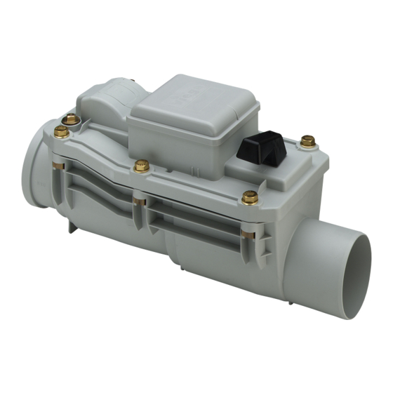
Page 9: Product Description
Product information Product description 2.3.1 Overview Fig. 3: Backflow trap Grundfix type 1 1 - lid 2 - emergency lock actuation 3 - shutter valve 4 - base unit 2.3.2 Operating mode In the case of backflow, the pipeline will be closed by the shutter valve in the backflow trap. -
Page 10: Handling
Handling 3 Handling Assembly information 3.1.1 Installation dimensions Fig. 5: Installation dimensions Assembly 3.2.1 Mount base unit The installation in the drainage pipeline may only be carried out by con- struction or specialised sanitary companies observing the building regu- lations and following this instruction for use. Grundfix backflow trap type 1 10 from 14... -
Page 11: Care And Maintenance
Handling Install the base unit horizontally into the base pipeline. Observe flow direction! At maximum, line up to the middle of the drainpipe. Close emergency shut-off (position "OFF‟). In this way, damage from flooding can be avoided before commis- sioning. Care and maintenance 3.3.1 Maintenance... - Page 12 Handling Place the emergency lock to "ZU (OFF)" position. Loosen screws on the lid. Carefully remove lid. Remove and clean flap. Grundfix backflow trap type 1 12 from 14...
- Page 13 Handling Check seal, if necessary, replace. Clean casing. Grease the seal of the partition on the casing side with silicon grease. Install flap. Position and screw on lid. Grundfix backflow trap type 1 13 from 14...
-
Page 14: Disposal
Handling Open and close the emergency lock with the manual actuator – check functionality. Disposal Separate the product and packaging materials (e. g. paper, metal, plastic or non-ferrous metals) and dispose of in accordance with valid national legal requirements. Grundfix backflow trap type 1 14 from 14...
Need help?
Do you have a question about the 4987.2 and is the answer not in the manual?
Questions and answers