
Related Manuals for Emerson Rosemount Analytical OPM 4000


Summary of Contents for Emerson Rosemount Analytical OPM 4000
- Page 1 Instruction Manual IM-105-4000, Rev 1.3 October 2008 OPM 4000 Opacity/Dust Density Monitor http://www.raihome.com...
- Page 3 HIGHLIGHTS OF CHANGES Effective August 31, 2006 Rev 1.0 Page Summary General Revised and removed the figures from Section 8, Drawings, and relocated them to their applicable sections. Changed all references of the Micro-turn 200 to read as the Zero Jig. Page 1-1 Added information under Component Checklist.
- Page 4 HIGHLIGHTS OF CHANGES (CONTINUED) Effective August 31, 2006 Rev 1.0 (Continued) Page Summary Page 3-2 Added Stack Exit Correlation Computation information and Figure 3-1, Lx and Lt Stack Dimensions. Page 3-3 Reformatted body text into bulleted lists and procedural steps. Page 4-1 Added Overview and bulleted list.
- Page 5 HIGHLIGHTS OF CHANGES (CONTINUED) Effective January, 2007 Rev 1.1 (Continued) Page Summary Page 2-20 Revised the Beam Alignment Procedure. Replaced Figure 2-15, Alignment of the Transceiver. Page 4-3 Revised steps 3 and 5 under Alarm Set Point Adjustments, Alarm Time Delay Adjustments, and Auto Cal Timer Adjustments.
-
Page 7: Table Of Contents
Instruction Manual IM-105-4000, Rev 1.3 OPM 4000 October 2008 Table of Contents Essential Instructions........i Preface . - Page 8 Instruction Manual IM-105-4000, Rev 1.3 OPM 4000 October 2008 SECTION 4 Overview ..........4-1 Operation Control Unit Operations .
- Page 9 Instruction Manual IM-105-4000, Rev 1.3 OPM 4000 October 2008 APPENDIX A Safety Instructions ........A-2 Safety Data APPENDIX B Returning Material .
- Page 10 Instruction Manual IM-105-4000, Rev 1.3 OPM 4000 October 2008 TOC-4...
-
Page 11: Essential Instructions
ESSENTIAL READ THIS PAGE BEFORE PROCEEDING! INSTRUCTIONS Emerson Process Management designs, manufactures and tests its products to meet many national and international standards. Because these instruments are sophisticated technical products, you MUST properly install, use and maintain them to ensure they continue to operate within their normal specifications. -
Page 12: Preface
Instruction Manual IM-105-4000, Rev 1.3 OPM 4000 October 2008 PREFACE The purpose of this manual is to provide information concerning the components, functions, installation and maintenance of the OPM 4000. Some sections may describe equipment not used in your configuration. The user should become thoroughly familiar with the operation of this module before operating it. - Page 13 In addition to the CSC, you may also contact Field Watch. Field Watch coordinates Emerson Process Management’s field service throughout the U.S. and abroad. Phone: 1-800-654-RSMT (1-800-654-7768) Emerson Process Management may also be reached via the Internet through e-mail and the World Wide Web: e-mail: GAS.CSC@emerson.com World Wide Web: www.raihome.com...
- Page 14 Instruction Manual IM-105-4000, Rev 1.3 OPM 4000 October 2008...
-
Page 15: Component Checklist
Specifications ........page 1-7 COMPONENT A typical Rosemount Analytical OPM 4000 Opacity/Dust Density Monitor should contain the items shown in Figure 1-1. Sheet 1 shows the assembly on... - Page 16 Instruction Manual IM-105-4000, Rev 1.3 OPM 4000 October 2008 Figure 1-1. Typical System Package (Sheet 1 of 2) In st ru ct IM -1 io n M an M ay 05 -4 00 0 ua l 20 06 R ev .
- Page 17 Instruction Manual IM-105-4000, Rev 1.3 OPM 4000 October 2008 Figure 1-1. Typical System Package (Sheet 2 of 2) 1. Terminal Board 2. Mounting Plate Air Blower Air Filter Air Hose with Clamps Retro Reflector with Air Plenum attached Notes: 1. Plug air blower into an external AC power source. 2.
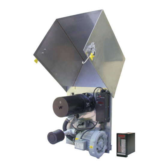
- Page 18 Instruction Manual IM-105-4000, Rev 1.3 OPM 4000 October 2008 Figure 1-2. Transceiver Assembly with Weather Cover Weather Cover Service Module Terminal Board Transceiver Mounting Plate Control Duplexer Unit Filter Air Blower Opacity data can also serve as a rough indicator of combustion efficiency. Extreme changes in opacity may indicate inefficient combustion or boiler problems.
-
Page 19: Opm 4000 System Features
Instruction Manual IM-105-4000, Rev 1.3 OPM 4000 October 2008 OPM 4000 System Transmissometer/Retro Reflector Features The OPM 4000 is a precision, double-pass, dual beam transmissometer that consists of a transceiver (transmitter/receiver) mounted on one side of a stack or duct and a passive reflector mounted on the opposite side. The light source, photo detectors and all measurement/reference optics used in opacity measurement are housed in the transceiver. -
Page 20: Normal Mode Of Operation
Instruction Manual IM-105-4000, Rev 1.3 OPM 4000 October 2008 Normal Mode of The dual beam measurement system has a stack mounted transmissometer sensor system that consists of an optical transceiver mounted on one side of Operation the stack and a retro reflector mounted on the other (Figure 1-3). To avoid errors due to ambient light, the lamp is electronically modulated and projects a collimated beam of light, which is split into a reference beam, and a measurement beam by an optical beam splitter. -
Page 21: Internal Calibration System, Zero Mode
Instruction Manual IM-105-4000, Rev 1.3 OPM 4000 October 2008 Internal Calibration Zero and span calibration checks can be initiated manually, automatically, or by a PLC or computer. During the zero calibration mode a calibrated zero System, Zero Mode reflector is placed in front of the transceiver optical package testing all optical surfaces and electronic components to assure zero point has not changed. - Page 22 Instruction Manual IM-105-4000, Rev 1.3 OPM 4000 October 2008 OPM 4000 Specifications Configuration Speed: 1200-38,400 baud, type RS-232, and RS-485 Transceiver Service module Display 5/8 inch (15,9 mm), 4-digit LED, selectable for % opacity and % transmittance Local Zero/Span Manual on demand Test Jacks Transceiver to remote control current loop Diagnostics...
-
Page 23: Overview
Instruction Manual IM-105-4000, Rev 1.3 OPM 4000 October 2008 Section 2 Installation Overview ........page 2-1 Installation Considerations . -
Page 24: Installation Considerations
Instruction Manual IM-105-4000, Rev 1.3 OPM 4000 October 2008 INSTALLATION CONSIDERATIONS Choose an Installation The primary considerations for choosing a site for the OPM 4000 are Site accessibility, ambient environmental conditions, and locating the unit to obtain a representative sample of the process. The following general guidelines should be considered. - Page 25 Instruction Manual IM-105-4000, Rev 1.3 OPM 4000 October 2008 Figure 2-1. Installation Clearances and Weather Cover Dimensions 12.250 in. (311 mm) 6.125 in. (156 mm) R 7.5 in. (191 mm) 6.125 (156 mm) 6 to 8 in. (152 to 203 mm) 6 to 8 in.
-
Page 26: Regulatory/Process Considerations
Instruction Manual IM-105-4000, Rev 1.3 OPM 4000 October 2008 Regulatory/Process The EPA has established the following guidelines for choosing an opacity/dust density monitor installation site: Considerations 1. Locate the transmitter across a section of a duct or stack that will provide a particulate matter flow through the path of the transmitter beam representative of the duct or stack flow. -
Page 27: Mechanical Installation
Instruction Manual IM-105-4000, Rev 1.3 OPM 4000 October 2008 MECHANICAL Perform each of the Mechanical Installation tasks before wiring the OPM 4000 system and aligning the beam. These tasks include: INSTALLATION • Installation of Stack Flanges • Mounitg the Air Plenum and Weather Covers •... - Page 28 Instruction Manual IM-105-4000, Rev 1.3 OPM 4000 October 2008 Figure 2-3. Mounting the Stack Flanges STACKS UNDER 6 FEET ACROSS 6 in. - 8 in. 3 in. Sch 40 (152 - 203 mm) Mounting Nipple VERTICAL AXIS 2-1/2 in. (64 mm) GAS FLOW Pipe Size to Span Stack or Breeching...
- Page 29 Instruction Manual IM-105-4000, Rev 1.3 OPM 4000 October 2008 Figure 2-4. Stack Flange Installation Mounting stack flanges on a stack over 6 feet in diameter 1. Form two mounting holes in the stack at locations specified in Installation Considerations. Holes must be on the same horizontal and vertical axes.
-
Page 30: Mounting The Air Plenum And Weather Covers
Instruction Manual IM-105-4000, Rev 1.3 OPM 4000 October 2008 5. The flanges must be aligned so that the total deviation of the light source flange relative to a common centerline does not exceed ±1 the retro reflector flange does not exceed ±3 . - Page 31 Instruction Manual IM-105-4000, Rev 1.3 OPM 4000 October 2008 Figure 2-5. Transceiver and Retro Reflector Hinge Pins Hinge Pin 4. Working from the 3 in. pipe flange, assemble in the following order (Figure 2-6): a. gasket b. mounting plate c. gasket d.
-
Page 32: Attach Blowers
Instruction Manual IM-105-4000, Rev 1.3 OPM 4000 October 2008 Attach Blowers Connect an air blower to the air blower port on the transceiver using the air hoses and clamps. Connect the other air blower to the air blower port on the retro reflector using the air hoses and clamps. - Page 33 Instruction Manual IM-105-4000, Rev 1.3 OPM 4000 October 2008 Mounting the the OPM 4000 control unit is designed for rack mounting in a customer supplied control panel. Install the OPM 4000 control unit in the designated Control Unit control panel according to the following procedure. NOTE The control unit (Figure 2-8) should be mounted at eye level for best viewing of the display.
- Page 34 Instruction Manual IM-105-4000, Rev 1.3 OPM 4000 October 2008 Figure 2-9. Panel Cutout for Control Unit 1.75 in. (45 mm) minimum spacing to mount next unit above or below 0.630 in. (16 mm) minimum spacing CUTOUT 7.5 in. (191 mm) 3.13 in.
- Page 35 Instruction Manual IM-105-4000, Rev 1.3 OPM 4000 October 2008 Figure 2-10. Control Unit Dimensions 2-13...
-
Page 36: System Wiring Installation
Instruction Manual IM-105-4000, Rev 1.3 OPM 4000 October 2008 SYSTEM WIRING The following procedures outline the necessary wring connections for the OPM 4000 system. Terminal identifications for the control unit are shown in INSTALLATION Figure 2-11. Wiring diagrams are shown in Figure 2-12 and the pin designations are shown in Figure 2-13. - Page 37 Instruction Manual IM-105-4000, Rev 1.3 OPM 4000 October 2008 Terminal Board 1 (TB 1) to Terminal Board 2 (TB 2) 1. Connect terminals 3 and 4 on TB 1 to terminals 1 and 2 on TB 2. 2. Connect shield covering the wires from terminals 3 and 4 on TB 1 to terminal 1 on TB 1.
- Page 38 Instruction Manual IM-105-4000, Rev 1.3 OPM 4000 October 2008 Figure 2-12. Typical System Wiring 2-16...
- Page 39 Instruction Manual IM-105-4000, Rev 1.3 OPM 4000 October 2008 Duplexer and AC power Supply 1. Connect the line wire (terminal 11 of the control unit) to an AC power source. 2. Connect the neutral wire (terminal 12 of the control unit) to an AC power source.
-
Page 40: Beam Alignment Procedure
Instruction Manual IM-105-4000, Rev 1.3 OPM 4000 October 2008 BEAM ALIGNMENT NOTE Alignment can not be done unless the power is applied to the stack mounted PROCEDURE service module. The control unit does not have to be connected or powered to perform an alignment. - Page 41 Instruction Manual IM-105-4000, Rev 1.3 OPM 4000 October 2008 1. Turn on the power to all air purge systems and the service module. 2. Adjust the 3 adjusting bolts on the middle plate so it is level and parallel to the mating flange.
- Page 42 Instruction Manual IM-105-4000, Rev 1.3 OPM 4000 October 2008 2-20...
-
Page 43: Overview
6. Beam alignment procedure has been completed. Startup Service Emerson Process Management is available to assist you; call our Customer Support Center (CSC) at 1-800-433-6076 for details and to schedule startup. http://www.raihome.com... -
Page 44: Stack Exit Correlation Computation
Instruction Manual IM-105-4000, Rev 1.3 OPM 4000 October 2008 Stack Exit Correlation NOTE The stack exit correlation is especially important to verify. If possible, all Computation dimensions should be verified by actual measurements. Lx/Lt is the ratio of the inside diameter at the top of the stack to the inside diameter of the stack where the instrument is located (Figure 3-1). -
Page 45: Verifying Instrument Operation And Configuration
Instruction Manual IM-105-4000, Rev 1.3 OPM 4000 October 2008 Verifying Instrument Before calibrating: Operation and • Beam alignment procedure must be completed as outlined in Section 2: Configuration Installation. • Apply power to both the control unit and the sensors for a minimum of 30 minutes before any adjustments are attempted. -
Page 46: Zero/Span Calibration Check
Instruction Manual IM-105-4000, Rev 1.3 OPM 4000 October 2008 Figure 3-2. OPLR Display “Edit Value” Light +19999 “Scroll Menu” Light MESSAGE Moves Message Cursor ALARM CAL. AUTO OPERATE ZERO SPAN HIGH OPACITY (ESC) EDIT Keys EDIT EDIT ENTER EDIT Hinged Cover ZERO/SPAN The zero calibration has been set at the factory by placing the instrument on an optical bench and using the flange-to-flange dimensions recorded in the... -
Page 47: Control Unit Operations
Instruction Manual IM-105-4000, Rev 1.3 OPM 4000 October 2008 Section 4 Operation Overview ........page 4-1 Control Unit Operations . -
Page 48: Manual Controls
Instruction Manual IM-105-4000, Rev 1.3 OPM 4000 October 2008 Figure 4-1. OPLR Display “Edit Value” Light +19999 “Scroll Menu” Light MESSAGE Moves Message Cursor ALARM CAL. AUTO OPERATE ZERO SPAN HIGH OPACITY (ESC) EDIT Keys EDIT EDIT ENTER EDIT Hinged Cover Maintenance Mode - Indicates a maintenance mode switch on the service module is in a maintenance position and the system is not displaying or outputting the opacity reading. -
Page 49: Alarm Set Point Adjustments
Instruction Manual IM-105-4000, Rev 1.3 OPM 4000 October 2008 Alarm Set Point 1. Open the hinged cover and press the EDIT (ESC) button [the red Edit (ESC) LED will light]. The message display will read QUICK MENU. Adjustments ▼ 2. Press the ENTER key then the EDIT key 1 time until the Display reads ALARM SET POINT. -
Page 50: Remote Calibration Cycle Acknowledgment
Instruction Manual IM-105-4000, Rev 1.3 OPM 4000 October 2008 Remote Calibration Dry contacts on terminal 4U (common) and 5U (NC) acknowledge when the calibration is in progress. This contact remains closed until calibration is Cycle Acknowledgment completed, i.e. both zero and span. SERVICE MODULE The service module is used to: •... - Page 51 Instruction Manual IM-105-4000, Rev 1.3 OPM 4000 October 2008 NORMAL / TEST This switch controls the EXTERNAL mA METER connections. In the normal mode the terminals are shorted. In the test mode the terminals are open and the current loop from the transceiver is interrupted allowing the use of an external current meter to be placed in series with the transceiver current output.
- Page 52 Instruction Manual IM-105-4000, Rev 1.3 OPM 4000 October 2008...
-
Page 53: Overview
Instruction Manual IM-105-4000, Rev 1.3 OPM 4000 October 2008 Section 5 Zero Jig and Neutral Density Filters Overview ........page 5-1 Using the Zero Jig . -
Page 54: Installation
Instruction Manual IM-105-4000, Rev 1.3 OPM 4000 October 2008 Installation The zero jig (Figure 5-2) on-line test reflector is inserted over the transceiver lens. The filters provided are marked in single-pass opacity; this is the same as double-pass with a correlation factor (OPLR) of 0.50. 1. - Page 55 Instruction Manual IM-105-4000, Rev 1.3 OPM 4000 October 2008 Figure 5-2. Zero Jig Installation Mounting Screw Alignment Pin Alignment Pin Fine Adjustment (Large Knob)
-
Page 56: Coarse Adjustments
Instruction Manual IM-105-4000, Rev 1.3 OPM 4000 October 2008 Coarse Adjustments Opacity Below Zero If the opacity reading is below zero and you can not reach zero after you have turned the adjustment knob as far as it will go into the zero jig housing, perform the following procedure: Do not force the knob. -
Page 57: Filter Certification
Specification 1, Section 7.1.3 Attenuation Calibration. Filter Certification QA/QC testing by Emerson Process Management of the filters at an interval of not more than 6 months is recommended. Filter certification, replacement, or additional neutral density filters are available from Emerson Process Management. - Page 58 Instruction Manual IM-105-4000, Rev 1.3 OPM 4000 October 2008...
-
Page 59: Overview
Instruction Manual IM-105-4000, Rev 1.3 OPM 4000 October 2008 Section 6 Zero and Span Calibration Clear on Stack Zero and Span Calibration ... . page 6-1 Zero Reflector Adjustment ......page 6-3 Span Filter Mark . - Page 60 Instruction Manual IM-105-4000, Rev 1.3 OPM 4000 October 2008 Figure 6-1. Zero Reflector Protective Window Zero Reflector Figure 6-2. Zero Calibration R/M Signal Processor Board PT-1 Zero PT-3 Span...
-
Page 61: Zero Reflector Adjustment
Instruction Manual IM-105-4000, Rev 1.3 OPM 4000 October 2008 8. With the fine adjustment (large knob), adjust the zero jig until the opacity reading is 0-1%. Lock the fine adjustment. 9. Place high opacity filter (for best results at least an 0.8 OD) in the slot provided in the zero jig. -
Page 62: Span Filter Mark
Instruction Manual IM-105-4000, Rev 1.3 OPM 4000 October 2008 SPAN FILTER MARK The span filter mark must be performed in order to enter the span value into the control unit. 1. With the ZERO switch in the ZERO position, place the SPAN switch in the SPAN position. - Page 63 Instruction Manual IM-105-4000, Rev 1.3 OPM 4000 October 2008 1. Remove the transceiver and retro reflector from the hinge pins. 2. Remove the service module and install the system on test stands at the correct flange-to-flange distance plus 11 in. (279,4 mm). The additional 11 in.
- Page 64 Instruction Manual IM-105-4000, Rev 1.3 OPM 4000 October 2008...
-
Page 65: Overview
Instruction Manual IM-105-4000, Rev 1.3 OPM 4000 October 2008 Section 7 Maintenance Overview ........page 7-1 Preventive Maintenance Schedule . -
Page 66: Control Unit Preventive Maintenance
Instruction Manual IM-105-4000, Rev 1.3 OPM 4000 October 2008 Item to Check Frequency Procedure Air flow switch 3 months Ensure that air flow switch is operating properly. Refer to "Air Flow Switch" in Section 8: Troubleshooting. Air hoses and clamps 3 months Check for tightness and wear;... -
Page 67: Weather Cover/Blower Preventive Maintenance
Instruction Manual IM-105-4000, Rev 1.3 OPM 4000 October 2008 Cleaning - Accumulations of dirt and dust on components act as an insulating blanket preventing efficient heat dissipation. Dust on circuit boards and wires can cause arcing and short circuits resulting in damage to components or even instrument failure. -
Page 68: Corrective Maintenance
Instruction Manual IM-105-4000, Rev 1.3 OPM 4000 October 2008 CORRECTIVE MAINTENANCE Disconnect all power before installing or replacing components. Failure to disconnect power may result in electrical shock and/or damage to the equipment. NOTE Make sure to carefully record the wiring connections and locations before disconnecting. -
Page 69: Transceiver Fuse Replacement
Instruction Manual IM-105-4000, Rev 1.3 OPM 4000 October 2008 Figure 7-2. Transceiver Fuse Transceiver Fuse (F1) Transceiver Fuse 1. Remove the transceiver cover by removing the screw below the target viewing window and pulling the housing straight back until it clears the Replacement optical plate. -
Page 70: Circuit Board Replacements
Instruction Manual IM-105-4000, Rev 1.3 OPM 4000 October 2008 Circuit Board The R/M Signal processor board and the Power/modulator board are located directly across from each other inside the transceiver housing, see Figure 7-4. Replacements The CPU board and the backup memory module are located inside of the control unit, see Figure 7-6. - Page 71 Instruction Manual IM-105-4000, Rev 1.3 OPM 4000 October 2008 Figure 7-5. Power/Modulator Board Replacement Iris Assembly Socket Head Cap Screws Socket Head Cap Screws Rotary Solenoid Zero Arm Central Processing Unit (CPU) Board Replacement Procedures 1. Remove screw on top of the control unit (Figure 7-6). 2.
- Page 72 Instruction Manual IM-105-4000, Rev 1.3 OPM 4000 October 2008 Backup Memory Module 1. Remove screw on top of the control unit (Figure 7-6). 2. Open control unit front panel to access the backup memory module. 3. Press on sides of chip and pull back to remove. 4.
-
Page 73: Troubleshooting
Instruction Manual IM-105-4000, Rev 1.3 OPM 4000 October 2008 Section 8 Troubleshooting Troubleshooting ....... . . page 8-1 Removing covers from the optical assembly or making optical repairs or adjustments in an unsuitable environment can affect the accuracy of the unit. -
Page 74: Air Flow Switch
Instruction Manual IM-105-4000, Rev 1.3 OPM 4000 October 2008 Problem Possible Cause Remedy No stack power fault message. Service module lost power or Check power, check SM fuse. failed Replace as needed. Refer to "Service Module Fuse Replacement" in Section 7: Maintenance. -
Page 75: Spare Parts
Spare Parts ........page 9-1 SPARE PARTS Contact an Emerson Process Management sales department with the serial number of your instrument and they will make recommendations based on your system. - Page 76 Instruction Manual IM-105-4000, Rev 1.3 OPM 4000 October 2008 Figure Num. Description 1A99993H20 Replacement 2” ND filter, 0.5 ±0.04 OD. 68.38% opacity, 31.62% transmittance 1A99993H21 Replacement 2” ND filter, 0.6 ±0.048 OD. 74.88% opacity, 25.12% transmittance 1A99993H22 Replacement 2” ND filter, 0.7 ±0.056 OD. 80.05% opacity, 19.95% transmittance 1A99993H23 Replacement 2”...
- Page 77 Instruction Manual IM-105-4000, Rev 1.3 OPM 4000 October 2008 Appendix A Safety Data Safety Instructions ........page A-2 http://www.raihome.com...
- Page 78 Instruction Manual IM-105-4000, Rev 1.3 OPM 4000 October 2008 IMPORTANT SAFETY INSTRUCTIONS SAFETY INSTRUCTIONS FOR THE WIRING AND INSTALLATION OF THIS APPARATUS The following safety instructions apply specifically to all EU member states. They should be strictly adhered to in order to assure compliance with the Low Voltage Directive.
- Page 79 Instruction Manual IM-105-4000, Rev 1.3 OPM 4000 October 2008 DŮLEŽITÉ Bezpečnostní pokyny pro zapojení a instalaci zařízení Následující bezpečnostní pokyny se speciálně vztahují na všechny členské státy EU. Pokyny by měly být přísně dodržovány, aby se zajistilo splnění Směrnice o nízkém napětí. Pokud nejsou pokyny nahrazeny místními či národními normami, měly by je dodržovat i nečlenské...
- Page 80 Instruction Manual IM-105-4000, Rev 1.3 OPM 4000 October 2008 VIGTIGT Sikkerhedsinstruktion for tilslutning og installering af dette udstyr. Følgende sikkerhedsinstruktioner gælder specifikt i alle EU-medlemslande. Instruktionerne skal nøje følges for overholdelse af Lavsspændingsdirektivet og bør også følges i ikke EU-lande medmindre andet er specificeret af lokale eller nationale standarder.
- Page 81 Instruction Manual IM-105-4000, Rev 1.3 OPM 4000 October 2008 BELANGRIJK Veiligheidsvoorschriften voor de aansluiting en installatie van dit toestel. De hierna volgende veiligheidsvoorschriften zijn vooral bedoeld voor de EU lidstaten. Hier moet aan gehouden worden om de onderworpenheid aan de Laag Spannings Richtlijn (Low Voltage Directive) te verzekeren. Niet EU staten zouden deze richtlijnen moeten volgen tenzij zij reeds achterhaald zouden zijn door plaatselijke of nationale voorschriften.
- Page 82 Instruction Manual IM-105-4000, Rev 1.3 OPM 4000 October 2008 BELANGRIJK Veiligheidsinstructies voor de bedrading en installatie van dit apparaat. Voor alle EU lidstaten zijn de volgende veiligheidsinstructies van toepassing. Om aan de geldende richtlijnen voor laagspanning te voldoen dient men zich hieraan strikt te houden. Ook niet EU lidstaten dienen zich aan het volgende te houden, tenzij de lokale wetgeving anders voorschrijft.
- Page 83 Instruction Manual IM-105-4000, Rev 1.3 OPM 4000 October 2008 WICHTIG Sicherheitshinweise für den Anschluß und die Installation dieser Geräte. Die folgenden Sicherheitshinweise sind in allen Mitgliederstaaten der europäischen Gemeinschaft gültig. Sie müssen strickt eingehalten werden, um der Niederspannungsrichtlinie zu genügen. Nichtmitgliedsstaaten der europäischen Gemeinschaft sollten die national gültigen Normen und Richtlinien einhalten.
- Page 84 Instruction Manual IM-105-4000, Rev 1.3 OPM 4000 October 2008 ΣΗΜΑΝΤΙΚΟ Οδηγιεσ ασφαλειασ για την καλωδιωση και εγκατασταση τησ συσκευησ Οι ακόλουθες οδηγίες ασφαλείας εφαρµόζονται ειδικά για όλες τις χώρες µέλη της Ευρωπαϊκής Κοινότητας. Θα πρέπει να ακολουθούνται αυστηρά ώστε να εξασφαλιστεί η συµβατότητα µε τις οδηγίες για τη Χαµηλή Τάση. Χώρες...
- Page 85 Instruction Manual IM-105-4000, Rev 1.3 OPM 4000 October 2008 OLULINE TEAVE Juhtmestiku ja seadme paigaldamisega seotud ohutusjuhised Alljärgnevad ohutusjuhised rakenduvad eriti kõigi Euroopa Liidu liikmesriikide suhtes. Antud juhiseid tuleb täpselt järgida, et kindlustada vastavus madalpinge direktiiviga. Euroopa Liitu mittekuuluvad riigid peavad samuti alljärgnevaid juhiseid järgima, va juhul, kui on olemas vastavad kohalikud riiklikud standardid.
- Page 86 Instruction Manual IM-105-4000, Rev 1.3 OPM 4000 October 2008 TÄRKEÄÄ Turvallisuusohje, jota on noudatettava tämän laitteen asentamisessa ja kaapeloinnissa. Seuraavat ohjeet pätevät erityisesti EU:n jäsenvaltioissa. Niitä täytyy ehdottomasti noudattaa jotta täytettäisiin EU:n matalajännitedirektiivin (Low Voltage Directive) yhteensopivuus. Myös EU:hun kuulumattomien valtioiden tulee nou-dattaa tätä...
- Page 87 Instruction Manual IM-105-4000, Rev 1.3 OPM 4000 October 2008 IMPORTANT Consignes de sécurité concernant le raccordement et l'installation de cet appareil. Les consignes de sécurité ci-dessous s'adressent particulièrement à tous les états membres de la communauté européenne. Elles doivent être strictement appliquées afin de satisfaire aux directives concernant la basse tension.
- Page 88 Instruction Manual IM-105-4000, Rev 1.3 OPM 4000 October 2008 FONTOS Biztonsági előírások a készülék vezetékeléséhez és üzembeállításához A következő biztonsági előírások kifejezetten vonatkoznak az összes EU-tagállamra. Ezeket szigorúan be kell tartani a Kisfeszültségű irányelvnek való megfelelés biztosításához. A nem EU-tagállamok szintén tartsák be a következőket, kivéve ha a helyi és nemzeti szabványok azt másként nem írják elő.
- Page 89 Instruction Manual IM-105-4000, Rev 1.3 OPM 4000 October 2008 IMPORTANTE Norme di sicurezza per il cablaggio e l'installazione dello strumento. Le seguenti norme di sicurezza si applicano specificatamente agli stati membri dell'Unione Europea, la cui stretta osservanza è richiesta per garantire conformità...
- Page 90 Instruction Manual IM-105-4000, Rev 1.3 OPM 4000 October 2008 SVARBU š io prietaiso laidų prijungimo ir instaliacijos saugos instrukcijos Toliau išvardinti saugumo reikalavimai taikomi konkrečiai visoms ES šalims narėms. Jų turi būti griežtai paisoma, kad būtų užtikrintai laikomasi Žemos įtampos direktyvos. Ne ES narės taip pat turi laikytis toliau pateikiamų...
- Page 91 Instruction Manual IM-105-4000, Rev 1.3 OPM 4000 October 2008 SVARĪGI Droš ības norādījumi š īs iekārtas pievienoš anai un uzstādīš anai Turpmākie drošības norādījumi attiecas uz visām ES dalībvalstīm. Tie ir stingri jāievēro, lai nodrošinātu atbilstību Zemsprieguma direktīvai. Turpmāk norādītais jāievēro arī valstīs, kas nav ES dalībvalstis, ja vien šos norādījumus neaizstāj vietējie vai valsts standarti.
- Page 92 Instruction Manual IM-105-4000, Rev 1.3 OPM 4000 October 2008 IMPORTANTI STRUZZJONIJIET TAS-SIGURTÀ GĦALL-WIRING U L-INSTALLAZZJONI TAT-TAGĦMIR L-istruzzjonijiet tas-sigurtà japplikaw speċifikament għall-Istati Membri ta' l-UE. Dawn għandhom jiġu osservati b'mod strett biex tkun żgurata l- konformità mad-Direttiva dwar il-Vultaġġ Baxx. Stati li mhumiex membri ta' l-UE għandhom ukoll ikunu konformi ma' dan li ġej ħlief jekk dawn ikunu sostituti mill-Istandards lokali jew Nazzjonali.
- Page 93 Instruction Manual IM-105-4000, Rev 1.3 OPM 4000 October 2008 VIKTIG Sikkerhetsinstruks for tilkobling og installasjon av dette utstyret. Følgende sikkerhetsinstruksjoner gjelder spesifikt alle EU medlemsland og land med i EØS-avtalen. Instruksjonene skal følges nøye slik at installasjonen blir i henhold til lavspenningsdirektivet. Den bør også følges i andre land, med mindre annet er spesifisert av lokale- eller nasjonale standarder.
- Page 94 Instruction Manual IM-105-4000, Rev 1.3 OPM 4000 October 2008 WAŻNE! Zalecenia dotyczące bezpieczeństwa w zakresie podłączania i instalacji tego urządzenia Następujące zalecenia dotyczą zwłaszcza stosowania urządzenia we wszystkich krajach Unii Europejskiej. Należy się ściśle do nich stosować w celu zapewnienia zgodności z dyrektywą niskonapięciową. W przypadku instalacji urządzenia w krajach nienależących do Unii Europejskiej należy również...
- Page 95 Instruction Manual IM-105-4000, Rev 1.3 OPM 4000 October 2008 IMPORTANTE Instruções de segurança para ligação e instalação deste aparelho. As seguintes instruções de segurança aplicam-se especificamente a todos os estados membros da UE. Devem ser observadas rigidamente por forma a garantir o cumprimento da Directiva sobre Baixa Tensão. Relativamente aos estados que não pertençam à...
- Page 96 Instruction Manual IM-105-4000, Rev 1.3 OPM 4000 October 2008 DÔLEŽITÉ Bezpečnostné pokyny pre zapojenie káblov a inš taláciu tohto prístroja Nasledovné bezpečnostné pokyny sa vzt’ahujú konkrétne na všetky členské štáty EÚ. Musia byt’ striktne dodržané, aby sa zaistila zhoda so Smernicou o nízkom napätí.
- Page 97 Instruction Manual IM-105-4000, Rev 1.3 OPM 4000 October 2008 POMEMBNO Varnostna navodila za povezavo in vgradnjo naprave Naslednja varnostna navodila veljajo za vse države članice EU. Zaradi zagotovitve skladnosti z nizkonapetostno direktivo morate navodila strogo upoštevati. V državah, ki niso članice EU, je treba upoštevati tudi naslednje smernice, razen če jih ne zamenjujejo lokalni ali nacionalnimi standardi.
- Page 98 Instruction Manual IM-105-4000, Rev 1.3 OPM 4000 October 2008 IMPORTANTE Instrucciones de seguridad para el montaje y cableado de este aparato. Las siguientes instrucciones de seguridad, son de aplicacion especifica a todos los miembros de la UE y se adjuntaran para cumplir la normativa europea de baja tension.
- Page 99 Instruction Manual IM-105-4000, Rev 1.3 OPM 4000 October 2008 VIKTIGT Säkerhetsföreskrifter för kablage och installation av denna apparat. Följande säkerhetsföreskrifter är tillämpliga för samtliga EU-medlemsländer. De skall följas i varje avseende för att överensstämma med Lågspännings direktivet. Icke EU medlemsländer skall också...
- Page 100 Instruction Manual IM-105-4000, Rev 1.3 OPM 4000 October 2008 A-24...
- Page 101 RETURNING MATERIAL If factory repair of defective equipment is required proceed as follows: 1. Secure a return authorization from an Emerson Process Management Sales Office or Representative before returning the equipment. Equipment must be returned with complete identification in accordance with Emerson Process Management instructions or it will not be accepted.
- Page 102 Instruction Manual IM-105-4000, Rev 1.3 OPM 4000 October 2008...
- Page 103 Instruction Manual IM-105-4000, Rev 1.3 OPM 4000 October 2008 Appendix C ModBus Communications MODBUS The OPM 4000 is capable of Modbus communications. To communicate with the OPM 4000 via Modbus, connect the Modbus signal wires to the Isolated COMMUNICATIONS RS 485 terminals 1, 2, and 3 on the back of the Control Room Unit. These terminals are shown in Figure 2-11.
- Page 104 Instruction Manual IM-105-4000, Rev 1.3 OPM 4000 October 2008...
-
Page 105: Foreword
Instruction Manual IM-105-4000, Rev 1.3 OPM 4000 October 2008 Appendix D OPM 2000 Retrofit Instructions Foreword ........page D-1 Overview of the Upgrade . -
Page 106: Removal Of Existing Equipment
Instruction Manual IM-105-4000, Rev 1.3 OPM 4000 October 2008 REMOVAL OF EXISTING EQUIPMENT Remove Transceiver Perform the following tasks to remove components from the transceiver side of the OPM 2000. Retain or discard the components as instructed. Side Components 1. Remove the fiberglass enclosure. DO NOT discard the enclosure as it will be used after final installation. -
Page 107: Installation
Instruction Manual IM-105-4000, Rev 1.3 OPM 4000 October 2008 INSTALLATION Install Retro Reflector Perform the following tasks to install the OPM 2000 retrofit kit and the components that were retained for reuse on the retro reflector side. Side Components (Ref. Dwg. 3D39369) 1. - Page 108 Instruction Manual IM-105-4000, Rev 1.3 OPM 4000 October 2008 2. Mount the air purge adapter assembly as shown in Figure D-2. Mount the assembly to the OPM air window assembly (item 4) and secure with bolts and nuts. Torque in cross fashion, 25 inch pounds, then 50 inch pounds, and finally 85 inch pounds.
- Page 109 Instruction Manual IM-105-4000, Rev 1.3 OPM 4000 October 2008 Figure D-4. Air Flow Switches Wiring Diagram 8. Mount the retro reflector assembly to the air window assembly and secure with the two spring latches. 9. DO NOT install the weather cover until the instrument is operational and the alignment is complete.
- Page 110 Instruction Manual IM-105-4000, Rev 1.3 OPM 4000 October 2008 Figure D-5. Retrofit System Wiring Diagram...
- Page 111 Instruction Manual IM-105-4000, Rev 1.3 OPM 4000 October 2008 Install Transceiver Side Perform the following tasks to install the OPM 2000 retrofit kit and the components that were retained for reuse on the transceiver side. Components 1. Install 1/8 NPT pipe plugs (kit P/N 1927) in the air window assembly where the pressure switch fittings were removed.
-
Page 112: System Setup
Instruction Manual IM-105-4000, Rev 1.3 OPM 4000 October 2008 Install Stack Service Use the following procedure to install the stack service module. Refer to Figure D-7. Module 1. Mount the stack service module to the two studs on the sub plate and secure with the flat washers and nuts provided. -
Page 113: Retrofit Kit Parts List
Instruction Manual IM-105-4000, Rev 1.3 OPM 4000 October 2008 RETROFIT KIT The following is a listing of the items included in the OPM 2000 Retrofit Kit, part number 6A00223G01. PARTS LIST Part Number Description 6A00188G08 Zero jig: Micro-Turn 200 on-line test reflector kit with case. Stack service module Stack service module mounting plate with terminal strip and power receptacle. - Page 114 Instruction Manual IM-105-4000, Rev 1.3 OPM 4000 October 2008 D-10...
- Page 115 Instruction Manual IM-105-4000, Rev 1.3 OPM 4000 October 2008 Index Air Flow Switch ... . . 8-2 Installation Recommended Spare Parts . . .9-1 Air Plenum Installation ..2-9 Air Plenum .
- Page 116 Instruction Manual IM-105-4000, Rev 1.3 OPM 4000 October 2008 Index-2...
- Page 117 WARRANTY Rosemount Analytical warrants that the equipment manufactured and sold by it will, upon shipment, be free of defects in workmanship or material. Should any failure to conform to this warranty become apparent during a period of one year after the date of shipment, Rosemount Analytical shall, upon prompt written notice from the purchaser, correct such nonconformity by repair or replacement, F.O.B.
- Page 118 Republic of Singapore England T 713 467 6000 T 65 6 777 8211 T 44 1243 863121 F 713 827 3329 F 65 6 777 0947 F 44 1243 845354 E analytical@ap.emerson.com http://www.raihome.com © 2008 Emerson Process Management. All rights reserved.
Need help?
Do you have a question about the Rosemount Analytical OPM 4000 and is the answer not in the manual?
Questions and answers