Advertisement
Table of Contents
- 1 Table of Contents
- 2 Safety Rules
- 3 Legend
- 4 Decals
- 5 Decals
- 6 Specifications
- 7 Control Panel
- 8 Pre-Operation Inspection
- 9 Workplace Inspection
- 10 Function Tests
- 11 Operating Instructions
- 12 Transport and Lifting Instructions
- 13 Maintenance
- 14 Schematic
- 15 Inspection and Repair Log
- Download this manual
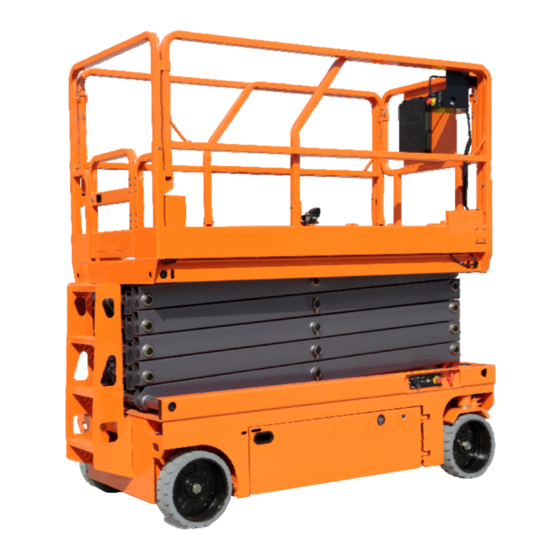
SELF-PROPELLED SCISSOR LIFTS
OPERATOR'S MANUAL
For S0608EH/S0808EH/S0812EH/S1012EH/S1212EH/S1412-EHXC
For S0608E/S0808E/S0812E/S1012E/S1212E/S1412-EXC
Part Number: SM0110111A_Rev4.0
Zhejiang Dingli Machinery Co., Ltd.
with Maintenance Information
( Hydraulic Motor / DC Motor Drive )
THE M ANUFACTURER SHALL NOT BE HELD LIABLE IN CASE OF FAULTS
OR ACCIDENTS DUE TO NEGLIGENCE, INCAPACITY, INSTALLATION BY
UNQUALIFIED TECHNICIANS AND IM PROPER USE OF THE MACHINE
DO NOT OPERATE THIS M ACHINE UNTIL YOU READ AND UNDERSTAND
ALL THE DANGERS,W ARNINGS AND CAUTIONS IN THIS MANUAL
WARNING
Fourth Edition, October 2018 Printing
Advertisement
Table of Contents


Need help?
Do you have a question about the S0608EH and is the answer not in the manual?
Questions and answers