Table of Contents
Advertisement
Quick Links
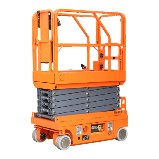
SELF-PROPELLED SCISSOR LIFTS
OPERATOR'S MANUAL
Part Number: SM0117119A_Rev1.1
Zhejiang Dingli Machinery Co., Ltd.
with Maintenance Information
( For S056-RS )
THE M AN UFACTU RER SHALL NO T BE HELD LIABLE IN CASE OF FAULTS
O R AC CI DENTS D UE TO NEG LI GENC E, I NCAPACITY, INSTALLATION BY
U NQ UALIFIED TEC HN IC IAN S AN D IMPROPER USE OF THE MACHINE
D O NO T OPERATE TH IS M AC HI NE U N TI L YOU READ AND UNDERSTAND
ALL THE D ANG ER S,W ARN IN GS AND CAUTIONS IN THIS MANUAL
WARNING
First Edition, August 2018 Printing
Advertisement
Table of Contents

Related Manuals for DINGLI S056-RS


Summary of Contents for DINGLI S056-RS
- Page 1 SELF-PROPELLED SCISSOR LIFTS OPERATOR’S MANUAL with Maintenance Information ( For S056-RS ) WARNING THE M AN UFACTU RER SHALL NO T BE HELD LIABLE IN CASE OF FAULTS O R AC CI DENTS D UE TO NEG LI GENC E, I NCAPACITY, INSTALLATION BY...
-
Page 3: Table Of Contents
Comply with employer, job site and the machine at all times. If you have any governmental rules. questions, please call DINGLI Machinery. Read, understand and follow the instructions in this and other manuals supplied with this machine. -
Page 5: Safety Rules
OPERATOR’S MANUAL with Maintenance Information Safety Rules Danger Decal Legend Failure to obey the instructions and DINGLI product decals use symbols, color coding and signal words to identify the safety rules in this manual will following: result in death or serious injury. - Page 6 Keep operator safety in mind at all times. maximum capacity of the platform extension. Use mild soap and water to clean safety signs. Maximum capacity – S056-RS Do not use solvent-based cleaners because Maximum occupants (Indoor use ONLY) they may damage the safety sign material.
- Page 7 Application Do not place ladders or scaffolds in the force occupants platform or against any part of this machine. S056-RS Indoor 400N Do not transport tools and materials unless Do not use the machine as a crane. they are evenly distributed and can be safely...
- Page 8 Be aware of extended platform position(s) Maximum side slope rating stowed when moving the machine. Model Check the work area for overhead obstructions or other possible hazards. S056-RS 25% (14°) 25% (14°) Note: Slope rating is subject to ground conditions and adequate traction.
- Page 9 OPERATOR’S MANUAL with Maintenance Information Safety Rules Explosion and Fire Hazard Do not operate the machine or charge the batteries in hazardous locations where potentially flammable or explosive gases or particles may be present. Be aware of crushing hazards when grasping the platform guard rail.
- Page 10 OPERATOR’S MANUAL with Maintenance Information Safety Rules Tip-over Hazard Do not use batteries that weigh less than the original equipment. Batteries are used as counterweight and are critical to machine stability. Each battery must weigh 32.7 kg. The Batteries contain acid. Always wear protective batteries must weigh a minimum of 65.4 kg.
-
Page 11: Legend
OPERATOR’S MANUAL with Maintenance Information Legend Legend 10 Ground control Platform control 11 Battery charger Platform guard rails 12 Main power switch Platform extension release pedal 13 Steer wheels Platform entry gate 14 Scissor arms Main platform 15 Safety arm Lift cylinder 16 Lanyard anchorage point Entry ladder... -
Page 12: Decals
09310031 Decal, Instructions-Maximum wheel load 570kg 09310004 Decal, Instructions-Emergency lower 09310034 Decal, Notice-Main power switch operation 09330001 Decal, Instructions-Safety arm 09640065 Decal, Cosmetic-S056-RS 09440007 Decal, Caution-Max. manual force 400N 09940003 Decal, Label-E-Tech 09440011 Decal, Label-Lanyard anchorage point 09540001 Decal, Label-CE... - Page 13 OPERATOR’S MANUAL with Maintenance Information Decals Safety tape...
- Page 14 OPERATOR’S MANUAL with Maintenance Information Decals...
-
Page 15: Specifications
It should be used only with Controls Proportional adequate safety factors. AC outlet in platform Standard Continuous improvement of our products is a DINGLI policy. Product specifications are subject to change without notice or obligation... -
Page 16: Control Panel
OPERATOR’S MANUAL with Maintenance Information Control Panel Ground Control Panel 5 Alarm 1 LED readout screen 4 Red Emergency Stop button Diagnostic readout Push in the red Emergency Stop button to the off position to stop all functions. Pull out 2 Platform up / down switch the red Emergency Stop button to the on position to operate the machine. - Page 17 OPERATOR’S MANUAL with Maintenance Information Control Panel Platform Control Panel Drive function select button Function enable switch Drive speed button Thumb rocker switch LED readout screen Proportional control handle Red Emergency Stop button Horn button Lift function select button...
- Page 18 OPERATOR’S MANUAL with Maintenance Information Control Panel Platform Control Panel Horn Button Function enable switch Press this button and the horn will sound. Press and hold the function enable switch Release the button and the horn will stop. to enable the drive/lift function. Thumb rocker switch Lift function select button Press the thumb rocker switch in either...
-
Page 19: Pre-Operating Instructions
OPERATOR’S MANUAL with Maintenance Information Pre-operation Inspection Do Not Operate Unless: Fundamentals √ You learn and practice the principles of It is the responsibility of the operator to perform a pre-operation inspection and routine safe machine operation contained in this maintenance. - Page 20 OPERATOR’S MANUAL with Maintenance Information Pre-operation Inspection Pre-operation Inspection Be sure that the operator’s manual are Check entire machine for: complete, legible and in the storage Cracks in welds or structural container located in the platform. components Be sure that all decals are legible and in ...
-
Page 21: Workplace Inspection
OPERATOR’S MANUAL with Maintenance Information Workplace Inspection Fundamentals Do Not Operate Unless: The workplace inspection helps the operator √ You learn and practice the principles of determine if the workplace is suitable for safe safe machine operation contained in this machine operation. -
Page 22: Function Tests
OPERATOR’S MANUAL with Maintenance Information Function Tests Fundamentals Do Not Operate Unless: The function tests are designed to discover √ You learn and practice the principles of any malfunctions before the machine is put safe machine operation contained in this into service. - Page 23 OPERATOR’S MANUAL with Maintenance Information Function Tests Select a test area that is firm, level and 10 Move up and hold the platform up / down free of obstruction. switch. Be sure the battery pack is connected. ⊙ Result: No function should operate. Pull out the main power switch to “on”...
- Page 24 OPERATOR’S MANUAL with Maintenance Information Function Tests 28 Press the drive function select button. The ⊙ Result: No functions should operate. indicator light should turn on. 19 Pull out the red Emergency Stop button to 29 Press and hold the function enable switch the on position.
- Page 25 OPERATOR’S MANUAL with Maintenance Information Function Tests Note: The brakes must be able to hold the ⊙ Result: The drive function should not work machine on any slope it is able to climb. in either direction. 46 Lower the platform and drive the machine Test Limited Drive Speed off the block.
- Page 26 OPERATOR’S MANUAL with Maintenance Information Function Tests 54 Press and hold the function enable switch on the control handle. 55 Depress the thumb rocker switch on top of the control handle in the direction identified by the blue and yellow arrow on the control panel.
-
Page 27: Operating Instructions
OPERATOR’S MANUAL with Maintenance Information Operating Instructions Fundamentals Do Not Operate Unless: This machine is a self-propelled hydraulic lift √ You learn and practice the principles of equipped with a work platform on the scissor safe machine operation contained in this mechanism. - Page 28 OPERATOR’S MANUAL with Maintenance Information Operating Instructions Move the control handle according to the Emergency Stop markings on the control panel. Push in the red Emergency Stop button to the To Steer off position at the ground controls or the platform controls to stop all machine functions.
- Page 29 OPERATOR’S MANUAL with Maintenance Information Operating Instructions Driving on a slope Operation from Ground with Determine the slope and side slope ratings for Controller the machine and determine the slope grade. Maintain safe distances between operator, Maximum slope rating, stowed position 25%, machine and fixed objects.
- Page 30 OPERATOR’S MANUAL with Maintenance Information Operating Instructions Remove the platform controls. To Extend and Retract Platform From inside the platform, remove the two Press the platform lock pin pedal on the front extension deck wire lock pins. extension deck by foot. Fold down the front rail assembly.
- Page 31 OPERATOR’S MANUAL with Maintenance Information Operating Instructions WARNING CODE DESCRIPTION warning Warning Description Denied motion code ECU ALARM PCU ALARM TM1 ALARM PRESS SENSOR ERROR Machine traction & steering (cage-up LOCK TRACTION IF CAGE UP traction speed must be 0 ) LEVEL SENSOR ERROR cage lifting MACHINE OVERLOAD...
- Page 32 OPERATOR’S MANUAL with Maintenance Information Operating Instructions warning Warning Description Denied motion code GPS LOCKER RenewRental 1 month RenewRental 3 month RenewRental 6 month RenewRental 12 month TRACTION MOTOR RIGHT SIDE NONE. Warning only OVERLOAD TRACTION MOTOR LEFT SIDE NONE. Warning only OVERLOAD TM1 PCB HIGH TEMPERATURE NONE.
- Page 33 OPERATOR’S MANUAL with Maintenance Information Operating Instructions ALARM CODE DESCRIPTION Alarm Denied Alarm Description code motion ECU E2PROM ALARM ECU WATCHDOG FAULT LMI OverLoad_Start ECU Thermal Calib. Init. Data Logger E2P Save On Err TMParameter Modified Password Inserted LMI OverLoad_End PCU CPU0 CANBUS TIMEOUT1 PCU CPU0 CANBUS TIMEOUT2 PCU CPU1 CANBUS TIMEOUT1...
- Page 34 OPERATOR’S MANUAL with Maintenance Information Operating Instructions Alarm Denied Alarm Description code motion ECU PIN48, INP13 REDUNDANT CHECK FAULT ECU PIN49, INP14 REDUNDANT CHECK FAULT ECU PIN50, INP15 REDUNDANT CHECK FAULT ECU PIN19, INP RELAY REDUNDANT CHECK FAULT ECU PIN20, INP BRAKE REDUNDANT CHECK FAULT ECU PIN23, INP M1 REDUNDANT CHECK FAULT ECU PIN24, INP M2 REDUNDANT CHECK FAULT PRESSURE SENSOR N.1 OPEN CIRCUIT OR SHORT TO GND...
- Page 35 OPERATOR’S MANUAL with Maintenance Information Operating Instructions Alarm Denied Alarm Description code motion ECU PIN01 OUT00 OPEN CIRCUIT ECU PIN01 OUT00 SHORT CIRCUIT ECU PIN02 OUT01 SHORT TO +VB ECU PIN02 OUT01 INTERNAL FAULT ECU PIN02 OUT01 CHECK FAULT ECU PIN02 OUT01 OPEN CIRCUIT ECU PIN02 OUT01 SHORT CIRCUIT ECU PIN04 OUT02 SHORT TO +VB ECU PIN04 OUT02 INTERNAL FAULT...
- Page 36 OPERATOR’S MANUAL with Maintenance Information Operating Instructions Alarm Denied Alarm Description code motion ECU PIN11 OUT06 OPEN CIRCUIT ECU PIN11 OUT06 SHORT CIRCUIT ECU PIN13 OUT07 SHORT TO +VB ECU PIN13 OUT07 INTERNAL FAULT ECU PIN13 OUT07 CHECK FAULT ECU PIN13 OUT07 OPEN CIRCUIT ECU PIN17 OUT07 SHORT CIRCUIT Pump Current Offset error Traction motor 1 Current Offset error...
- Page 37 OPERATOR’S MANUAL with Maintenance Information Operating Instructions Alarm Denied Alarm Description code motion TM OUT3 Over Current TM WatchDog Error TM WatchDog Validity Error TM Pump Open Circuit Tractor Motor1 Open circuit Tractor Motor2 Open circuit Traction Motor1 Wiring Error Traction Motor2 Wiring Error TM Excitation Open Circuit TM Excitation Wiring Error...
- Page 38 OPERATOR’S MANUAL with Maintenance Information Operating Instructions Alarm Denied Alarm Description code motion ECU OUT10 SHORT TO +VB ECU OUT10 INTERNAL FAULT ECU OUT10 CHECK FAULT ECU OUT10 OPEN CIRCUIT ECU OUT10 SHORT CIRCUIT ECU RELAY OUTPUT SHORT TO +VB ECU RELAY OUTPUT INTERNAL FAULT ECU RELAY OUTPUT CHECK FAULT ECU RELAY OUTPUT OPEN CIRCUIT...
- Page 39 OPERATOR’S MANUAL with Maintenance Information Operating Instructions Troubleshooting chart Code Possible failure reason Suggested operation Vehicle is overloaded Reduce the vehicle load The vehicle tilting level is greater than the Bring the vehicle to leveled ground, or to threshold setting. descend the platform to minimum position Check the system or to calibrate the ECU If you are certain the ground is well leveled...
- Page 40 OPERATOR’S MANUAL with Maintenance Information Operating Instructions Code Possible failure reason Suggested operation There is obstacle under the vehicle platform Remove the obstacle “ultrasonic” input failure Check the ultrasonic sensor The platform safety door is open Close the platform safety door Platform safety door switch failure Check the safety door micro switch When the platform is at minimum position,...
- Page 41 OPERATOR’S MANUAL with Maintenance Information Operating Instructions Code Possible failure reason Suggested operation There is too much load in the cage. Pump motor is in overload Reduce the weight. The empty load calibration of LMI function Redo the empty load calibration does not finish successfully The laden load calibration of LMI function Redo the empty load calibration...
- Page 42 OPERATOR’S MANUAL with Maintenance Information Operating Instructions Code Possible failure reason Suggested operation ECU Tilt sensor Y axis value failure Redo vehicle 0° level calibration Replace ECU, or redo vehicle 0° level ECU tilt sensor internal failure calibration Check the ECU key switch signal ECU key switch failure (diagnostic screen) ECU internal failure...
- Page 43 OPERATOR’S MANUAL with Maintenance Information Operating Instructions Code Possible failure reason Suggested operation ECU pin n.20 (IN BRAKE) failure Contact assistance, or replace ECU ECU internal failure Contact assistance, or replace ECU ECU pin n.23 (IN M1) failure Contact assistance, or replace ECU ECU internal failure Contact assistance, or replace ECU ECU pin n.24 (IN M2) failure...
- Page 44 OPERATOR’S MANUAL with Maintenance Information Operating Instructions Code Possible failure reason Suggested operation Scissor angle potentiometer n.1 converted Contact assistance, check the value too low potentiometer parameter setting Scissor angle potentiometer n.1 converted Contact assistance, check the value too high potentiometer parameter setting Scissor angle potentiometer n.1 internal Replace potentiometer...
- Page 45 OPERATOR’S MANUAL with Maintenance Information Operating Instructions Code Possible failure reason Suggested operation ECU pin n.02 (OUT 01): external load is Check harness and connection open circuit ECU internal failure Contact assistance, or replace ECU unit ECU pin n.02 (OUT 01): external load is Check harness and connection short circuit ECU internal failure...
- Page 46 OPERATOR’S MANUAL with Maintenance Information Operating Instructions Code Possible failure reason Suggested operation ECU watchdog failure ( internal short circuit ) replace ECU unit ECU internal failure Contact assistance, or replace ECU unit ECU pin n.08 (OUT 04): external load is Check harness and connection open circuit ECU internal failure...
- Page 47 OPERATOR’S MANUAL with Maintenance Information Operating Instructions Code Possible failure reason Suggested operation ECU pin n.13 (OUT 07) internal failure Contact assistance, or replace ECU unit ECU internal failure Contact assistance, or replace ECU unit ECU watchdog failure ( internal short circuit ) replace ECU unit ECU internal failure Contact assistance, or replace ECU unit ECU pin n.13 (OUT 07): external load is...
- Page 48 OPERATOR’S MANUAL with Maintenance Information Operating Instructions Code Possible failure reason Suggested operation M1(right side) traction motor harness short Check harness and connection circuit M1(right side) traction motor internal short Replace traction motor circuit Check TM parameter “Trac. Short R. Wrong TM1 parameter setting Setting”...
- Page 49 OPERATOR’S MANUAL with Maintenance Information Operating Instructions Code Possible failure reason Suggested operation Stop using the vehicle and cool down the Traction module internal temperature is high traction module Change the working location or reduce the The working surrounding of vehicle is too hot location temperature TM internal failure Replace TM...
- Page 50 OPERATOR’S MANUAL with Maintenance Information Operating Instructions Code Possible failure reason Suggested operation In the excitation circuit, there is no traction motor connected or traction motor is open Check traction motor connection, check circuit harness [valid for Separate Excitation TM only] Defective TM Replace TM Wrong excitation circuit connection:...
- Page 51 OPERATOR’S MANUAL with Maintenance Information Operating Instructions Code Possible failure reason Suggested operation ECU watchdog failure ( internal short circuit ) replace ECU unit ECU internal failure Contact assistance, or replace ECU unit ECU pin n.18 (OUT 09): external load is Check harness and connection open circuit ECU internal failure...
- Page 52 Contact assistance, or replace ECU unit ECU pin n.26 (OUT BRAKE 2): external load Check harness and connection is short circuit ECU internal failure Contact assistance, or replace ECU unit For more information, please consult the appropriate Dingli Service Dept.
- Page 53 Do not overfill. √ Use proper AC input voltage for charging as indicated on the charger. Dry Battery Filling and √ Use only a Dingli authorized battery and charger. Charging Instructions Remove the battery vent caps and permanently remove the plastic seal from To Charge Battery the battery vent openings.
-
Page 54: Transport And Lifting Instructions
OPERATOR’S MANUAL with Maintenance Information Transport and Lifting Instructions Observe and Obey: Brake Release Operation Chock the wheels to prevent the machine √ Common sense and planning must be from rolling. applied to control the movement of the Pull out the red Emergency Stop button to machine when lifting it with a crane or the on position at both the ground and forklift. - Page 55 OPERATOR’S MANUAL with Maintenance Information Transport and Lifting Instructions Securing to Truck or Trailer for Transit Always chock the machine wheels in preparation for transport. Retract and secure the extension deck(s). Turn the key switch to the off position and remove the key before transporting.
-
Page 56: Maintenance
OPERATOR’S MANUAL with Maintenance Information Maintenance Pre-delivery Preparation Report Observe and Obey: The pre-delivery preparation report contains √ Only routine maintenance items specified in checklists for each type of scheduled this manual shall be performed by the inspection. operator. Make copies of the Pre-delivery Preparation √... - Page 57 OPERATOR’S MANUAL with Maintenance Information Maintenance Pre-delivery Preparation Report Fundamentals Instructions It is the responsibility of the dealer to perform Use the operator’s manual on your machine. the Pre-delivery Preparation. The Pre-delivery Preparation consists of The Pre-delivery Preparation is performed completing the Pre-operation Inspection, the prior to each delivery.
- Page 58 OPERATOR’S MANUAL with Maintenance Information Maintenance Maintenance Inspection Report Model Checklist A Y N R Serial number A-1 Inspect the manuals and decals Date A-2 Pre-operation inspection Hour meter A-3 Check the Batteries Machine owner A-4 Check the Hydraulic Oil Level Inspected by (print) A-5 Function tests Inspector signature...
- Page 59 Decals Note: Contact your authorized DINGLI alert operators and personnel to the many distributor or DINGLI machinery if replacement possible hazards associated with using this manuals or decals are needed. machine. They also provide users with operation and maintenance information.
- Page 60 OPERATOR’S MANUAL with Maintenance Information Maintenance Perform Pre-operation Inspection Check the Batteries Completing a Pre-operation Inspection is essential to safe machine operation. The Pre-operation Inspection is a visual inspection Proper battery condition is essential to good performed by the operator prior to each work machine performance and operational safety.
- Page 61 OPERATOR’S MANUAL with Maintenance Information Maintenance Check the Hydraulic Oil Level Perform Function Tests Completing the function tests is essential to safe machine operation. Function tests are designed to discover any malfunctions before Maintaining the hydraulic oil at the proper level the machine is put into service.
- Page 62 OPERATOR’S MANUAL with Maintenance Information Maintenance Perform 30 Day Service The 30 day maintenance procedure is a one time procedure to be performed after the first 30 days or 40 hours of usage. After this interval, refer to the maintenance tables for continued scheduled maintenance.
- Page 63 Maintenance Checklist B Procedures Inspect the Batteries Remove the battery vent caps and check DINGLI requires that this procedure be the specific gravity of each battery cell with performed every 250 hours or quarterly, a hydrometer. Note the results. whichever comes first.
- Page 64 Note: If you have any further questions is less than 1.177. Replace the battery. regarding the battery charger operation, please contact the DINGLI Service 11 Check the battery acid level. If needed, Department. replenish with distilled water to 3 mm below the bottom of the battery fill tube.
- Page 65 OPERATOR’S MANUAL with Maintenance Information Maintenance Inspect the Electrical Wiring DINGLI requires that this procedure be Crushing hazard. Keep performed every 250 hours or quarterly, hands clear of the safety arm when lowering whichever comes first. the platform. Maintaining electrical wiring in good condition...
- Page 66 Maintenance Inspect the Tires and Wheels Test the Emergency Stop (including lock nut torque) DINGLI requires that this procedure be performed every 250 hours or quarterly, whichever comes first. DINGLI requires that this procedure be A properly functioning Emergency Stop is performed every 250 hours or quarterly, essential for safe machine operation.
- Page 67 OPERATOR’S MANUAL with Maintenance Information Maintenance Test the Key Switch Test the Automotive-style Horn (if equipped) DINGLI requires that this procedure be performed every 250 hours or quarterly, DINGLI requires that this procedure be whichever comes first. performed every 250 hours or quarterly, whichever comes first.
- Page 68 OPERATOR’S MANUAL with Maintenance Information Maintenance Test the Drive Brakes DINGLI requires that this procedure be ¤ Result: The machine does not stop within performed every 250 hours or quarterly, the specified braking distance. whichever comes first. Note: The brakes must be able to hold the Proper brake action is essential to safe machine on any slope it is able to climb.
- Page 69 Maintenance Test the Drive Speed - Stowed Test the Drive Speed-Raised Position Position DINGLI requires that this procedure be performed every 250 hours or quarterly, DINGLI requires that this procedure be whichever comes first. performed every 250 hours or quarterly, Proper drive functions are essential to safe whichever comes first.
- Page 70 Maintenance B-10 B-11 Test the Slow Drive Speed Perform Hydraulic Oil Analysis DINGLI requires that this procedure be DINGLI requires that this procedure be performed every 250 hours or quarterly, performed every 250 hours or quarterly, whichever comes first. whichever comes first.
- Page 71 Inspect the Hydraulic Tank Cap Check the Module Tray slider Venting System Components DINGLI requires that this procedure be DINGLI requires that this procedure be performed every 250 hours or quarterly, performed quarterly or every 250 hours, whichever comes first.
- Page 72 Maintenance Checklist C Procedures Test the Platform Overload System (if equipped) DINGLI requires that this procedure be performed every 500 hours or six months, whichever comes first or when the machine fails to lift the maximum rated load. Testing the platform overload system regularly is essential to safe machine operation.
- Page 73 OPERATOR’S MANUAL with Maintenance Information Maintenance Replace the Hydraulic Tank Breather DINGLI requires that this procedure be Press the [ESC] button then return to the performed every 500 hours or semi-annually, display page of step 5. whichever comes first. Fully raise the platform. Hold the toggle The hydraulic tank is a vented-type tank.
- Page 74 Checklist D Procedures Check the Scissor Arm Wear Pads Measure the distance between the number DINGLI requires that this procedure be one arm cross tube and the chassis deck performed every 1000 hours or annually, at the right side of the steer end of the whichever comes first.
- Page 75 OPERATOR’S MANUAL with Maintenance Information Maintenance Checklist E Procedure Test or Replace the Hydraulic Oil DINGLI requires that this procedure be Remove the oil drain plug at bottom. performed every 2000 hours or every two Drain all of the oil into a suitable container.
- Page 76 OPERATOR’S MANUAL with Maintenance Information Maintenance Component damage hazard. The pump can be damaged if operated without oil. Be careful not to empty the hydraulic tank while in the process of filling the hydraulic system. Do not allow the pump to cavitate.
-
Page 77: Schematic
OPERATOR’S MANUAL with Maintenance Information Schematic Hydraulic Schematic Upper Lift Cylinder Lift Cylinder Flat overload Option ( ) Sensor SCV3 SCV4 150Bar Steer Cylinder 0.7mm 1.5mm 1.0mm 1.0mm SCV2 SCV1 RPCV1 100bar 160bar Pump unit... - Page 78 OPERATOR’S MANUAL with Maintenance Information Schematic Electrical Schematic...
-
Page 79: Inspection And Repair Log
OPERATOR’S MANUAL with Maintenance Information Inspection and Repair Log Inspection and Repair Log Date Comments...
Need help?
Do you have a question about the S056-RS and is the answer not in the manual?
Questions and answers