Advertisement
Table of Contents
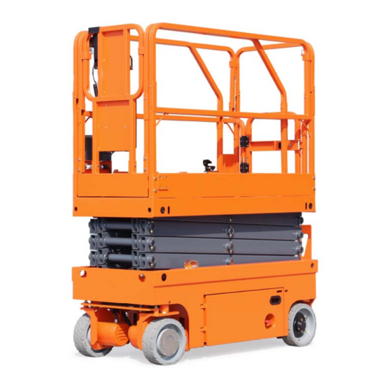
SELF-PROPELLED SCISSOR LIFTS
OPERATOR'S MANUAL
Part Number: SM0110113A_Rev8.1
Zhejiang Dingli Machinery Co., Ltd.
with Maintenance Information
S06-EH / S06-E
(Series 3)
THE M AN UFACTU RER SHALL NO T BE HELD LIABLE IN CASE OF FAULTS
O R AC CI DENTS D UE TO NEG LI GENC E, I NCAPACITY, INSTALLATION BY
U NQ UALIFIED TEC HN IC IAN S AN D IMPROPER USE OF THE MACHINE
D O NO T OPERATE TH IS M AC HI NE U N TI L YOU READ AND UNDERSTAND
ALL THE D ANG ER S,W ARN IN GS AND CAUTIONS IN THIS MANUAL
WARNING
Eighth Edition, August 2018 Printing
Advertisement
Table of Contents

Related Manuals for DINGLI S06-EH


Summary of Contents for DINGLI S06-EH
- Page 1 D O NO T OPERATE TH IS M AC HI NE U N TI L YOU READ AND UNDERSTAND ALL THE D ANG ER S,W ARN IN GS AND CAUTIONS IN THIS MANUAL Part Number: SM0110113A_Rev8.1 Zhejiang Dingli Machinery Co., Ltd. Eighth Edition, August 2018 Printing...
-
Page 3: Table Of Contents
Comply with employer, job site and part of your machine and should remain with governmental rules. the machine at all times. If you have any questions, please call DINGLI Machinery. Read, understand and follow the instructions in this and other manuals supplied with this machine. -
Page 5: Safety Rules
Safety Rules Danger Decal Legend Failure to obey the instructions and safety rules in this manual will DINGLI product decals use symbols, color coding and signal words to identify the result in death or serious injury. following: Do Not Operate Unless: Safety alert symbol —... - Page 6 Maximum capacity – S06-EH Maximum capacity – S06-E Maximum occupants (Indoor use) Maximum occupants (Outdoor use)
- Page 7 For outdoor use machine, do not raise the force occupants platform when wind speeds may exceed 12.5 m/s. If wind speeds exceed 12.5 m/s when the Outdoor 200N S06-EH platform is raised, lower the platform and do Indoor 400N not continue to operate the machine. Outdoor 200N...
- Page 8 Maximum side slope rating stowed increase the weight in the platform and the surface area of the platform or the load. Model Do not place ladders or scaffolds in the S06-EH 25% (14°) 25% (14°) platform or against any part of this machine. S06-E 25% (14°)
- Page 9 OPERATOR’S MANUAL with Maintenance Information Safety Rules Observe and use color-coded direction arrows on the platform controls for drive and steer functions. Do not operate a machine in the path of any crane or moving overhead machinery unless the controls of the crane have been locked out and/or precautions have been taken to prevent Do not climb down from the platform when any potential collision.
- Page 10 OPERATOR’S MANUAL with Maintenance Information Safety Rules Conduct a thorough pre-operation inspection Explosion Hazard of the machine and test all functions before each work shift. Immediately tag and remove from service a damaged or malfunctioning machine. Be sure all maintenance has been performed as specified in this manual Be sure all decals are in place and legible.
- Page 11 OPERATOR’S MANUAL with Maintenance Information Safety Rules Lockout after Each Use Select a safe parking location - firm level surface, clear of obstruction and traffic. Lower the platform. Turn the key switch to the off position and remove the key to secure from unauthorized use.
-
Page 12: Legend
OPERATOR’S MANUAL with Maintenance Information Legend Legend Platform guard rails 10 Non-steer tire Platform controls 11 Entry ladder Manual storage container 12 Battery charger (on opposite side of machine) (on the entry ladder end of machine) Platform extension 13 Safety arm Scissor Arms 14 Platform extension release pedal 6 Lift Cylinder... -
Page 13: Decals
Decal, Notice-Main power switch operation 09540001 Decal, Label-CE 09410001 Decal, Danger-Explosion/burn hazard 09430001 Decal, Danger-Safety arm 09430003 Decal, Danger-Keep away from moving parts 09640066 Decal, Cosmetic-S06-EH S06-EH 09640067 Decal, Cosmetic-S06-E S06-E Decal, Caution-Max. manual force 400N (Indoor) 09440009 200N (Outdoor) 09940003 Decal, Label-E-Tech... - Page 14 OPERATOR’S MANUAL with Maintenance Information Decals Safety tape...
- Page 15 OPERATOR’S MANUAL with Maintenance Information Decals...
-
Page 16: Specifications
Controls Proportional configurations. It should be used only with adequate safety factors. AC outlet in platform Standard Continuous improvement of our products is a DINGLI policy. Product specifications are subject to change without notice or obligation. - Page 17 Controls Proportional configurations. It should be used only with adequate safety factors. AC outlet in platform Standard Continuous improvement of our products is a DINGLI policy. Product specifications are subject to change without notice or obligation.
-
Page 18: Control Panel
OPERATOR’S MANUAL with Maintenance Information Control Panel Ground Control Panel For S06-EH Key switch Circuit breaker Turn the key switch to the platform position When the current was overloaded, the and the platform controls will operate. Turn circuit breaker will cut off the circuit. - Page 19 OPERATOR’S MANUAL with Maintenance Information Control Panel For S06-E Key switch Brake release switch. Turn the key switch to the platform Press this switch to “ON” position to position and the platform controls will activate the brake release function. operate. Turn the key switch to the off Press this switch.to “OFF”...
- Page 20 OPERATOR’S MANUAL with Maintenance Information Control Panel Platform Control Panel Thumb rocker switch Horn button Drive function select button Lift function select button Drive speed button Proportional control handle Red Emergency Stop button Function enable switch LED readout screen...
- Page 21 OPERATOR’S MANUAL with Maintenance Information Control Panel Platform Control Panel Thumb rocker switch Lift function select button Press the thumb rocker switch in either Press this button to activate the lift direction to activate steer function. function. Drive function select button Proportional control handle Press this button to activate the drive Lift function: Press and hold the function...
-
Page 22: Pre-Operation Inspection
OPERATOR’S MANUAL with Maintenance Information Pre-operation inspection Fundamentals Do Not Operate Unless: It is the responsibility of the operator to √ You learn and practice the principles of perform a pre-operation inspection and routine safe machine operation contained in this maintenance. - Page 23 OPERATOR’S MANUAL with Maintenance Information Per-operation inspection Pre-operation Inspection Check entire machine for Be sure that the operator’s manual are complete, legible and in the storage Cracks in welds or structural container located in the platform. components Be sure that all decals are legible and in ...
-
Page 24: Workplace Inspection
OPERATOR’S MANUAL with Maintenance Information Workplace Inspection Fundamentals Do Not Operate Unless: The workplace inspection helps the operator √ You learn and practice the principles of determine if the workplace is suitable for safe safe machine operation contained in this machine operation. -
Page 25: Function Tests
OPERATOR’S MANUAL with Maintenance Information Function Tests Fundamentals Do Not Operate Unless: The function tests are designed to discover √ You learn and practice the principles of any malfunctions before the machine is put safe machine operation contained in this into service. - Page 26 OPERATOR’S MANUAL with Maintenance Information Function Tests Select a test area that is firm, level and 10 Turn the key switch to off or platform free of obstruction. position. Be sure the battery pack is connected. 11 Move up and hold the platform up / down switch.
- Page 27 OPERATOR’S MANUAL with Maintenance Information Function Tests Test the Steering At the Platform Controls Note: When performing the steer and drive Test Emergency Stop function tests, stand in the platform facing the 19 Push in the platform red Emergency Stop steer end of the machine.
- Page 28 OPERATOR’S MANUAL with Maintenance Information Function Tests arrow on the control panel until the 44 Press the drive function select button. machine begins to move, then return the 45 Press and hold the function enable switch handle to the center position. on the control handle.
- Page 29 OPERATOR’S MANUAL with Maintenance Information Function Tests 53 Press and hold the function enable switch on the control handle. 54 Move the control handle in the direction indicated by the blue up arrow, and then move the control handle in the direction indicated by the yellow down arrow.
-
Page 30: Operating Instructions
OPERATOR’S MANUAL with Maintenance Information Operating Instructions The Operating Instructions section provides Do Not Operate Unless: instructions for each aspect of machine √ You learn and practice the principles of operation. safe machine operation contained in this It is the operator's responsibility to follow all operator's manual. - Page 31 OPERATOR’S MANUAL with Maintenance Information Operating Instructions Press and hold the function enable switch Emergency Stop on the control handle. Push in the red Emergency Stop button to the Move the control handle according to the off position at the ground controls or the markings on the control panel.
- Page 32 OPERATOR’S MANUAL with Maintenance Information Operating Instructions Driving on a slope Operation from Ground with Controller Determine the slope and side slope ratings for the machine and determine the slope grade. Maintain safe distances between operator, Maximum slope rating, stowed position 25%, machine and fixed objects.
- Page 33 OPERATOR’S MANUAL with Maintenance Information Operating Instructions Remove the platform controls. To Extend and Retract Platform From inside the platform, remove the two Press the platform lock pin pedal on the front extension deck wire lock pins. extension deck by foot. Fold down the front rail assembly.
- Page 34 OPERATOR’S MANUAL with Maintenance Information Operating Instructions Error indicator readout The LED readout screen displays fault codes that provide information about the machine operating status and about malfunctions. The fault codes listed in the following charts describe malfunctions and can aid in troubleshooting the machine by pinpointing the area or component affected.
- Page 35 OPERATOR’S MANUAL with Maintenance Information Operating Instructions Display Description Lift Reaction Motor Controller Hardware Failsafe Fault Controller Dependent Motor Controller Motor Output Fault Controller Dependent Motor Controller SRO Fault Controller Dependent Motor Controller Throttle Fault Controller Dependent Motor Controller Emergency Reverse Fault Controller Dependent Motor Controller HPD Fault Controller Dependent...
- Page 36 OPERATOR’S MANUAL with Maintenance Information Operating Instructions Display Description Lift Reaction Motor Field Open Disable Lifting and Driving Over 90% Load Warning Warning Only Left Motor Field Short Disable Lifting and Driving Right Motor Field Short Disable Lifting and Driving Over 99% Load Warning Warning Only Overloaded Platform Fault...
- Page 37 Joystick or PCU. Platform Joystick not in neutral at power-up Message: Make sure that the Joystick is in the neutral (upright) position. Check the neutral zone parameter setting in Dingli Scissor Programmer. If it’s OK, consider replacing the Joystick or the PCU.
- Page 38 Motor Controller Motor Output fault: Check wiring first then cycle power. If needed replace controller. Motor Controller SRO Fault: Look at motor enable delay with the Dingli Scissor Programmer, it may be too short. Make sure other Motor Controller parameters are properly selected.
- Page 39 Machine Tilted Beyond Safe Limits Fault: If the machine is tilted, find a way to make it level. If the machine is level, check the wiring to the tilt sensor and then the sensor itself. For more information, please consult the appropriate Dingli Service Dept.
- Page 40 Do not overfill. √ Use proper AC input voltage for charging as indicated on the charger. √ Use only a Dingli authorized battery and Dry Battery Filling and charger. Charging Instructions...
-
Page 41: Transport And Lifting Instructions
OPERATOR’S MANUAL with Maintenance Information Transport and Lifting Instructions Brake Release Operation Observe and Obey: For the Hydraulic Motor Drive Model √ Common sense and planning must be applied to control the movement of the Chock the wheels to prevent the machine machine when lifting it with a crane or from rolling. - Page 42 OPERATOR’S MANUAL with Maintenance Information Transport and Lifting Instructions Securing to Truck or Trailer for Transit Use a minimum of four chains or straps. Always chock the machine wheels in preparation for transport. Use chains or straps of ample load capacity. Retract and secure the extension deck(s).
- Page 43 OPERATOR’S MANUAL with Maintenance Information Transport and Lifting Instructions Observe and Obey: Lifting the Machine with a Forklift √ Only qualified riggers should rig and lift the machine. Be sure the extension deck, controls and component trays are secure. Remove all loose √...
- Page 44 Model X Axis Y Axis decks, controls and covers are secure. Remove all loose items on the machine. S06-EH 64.8 cm 59.1 cm Determine the center of gravity of your machine using the table and the picture on this S06-E 64.8 cm...
-
Page 45: Maintenance
OPERATOR’S MANUAL with Maintenance Information Maintenance Pre-delivery Preparation Report Observe and Obey: The pre-delivery preparation report contains √ Only routine maintenance items specified in checklists for each type of scheduled this manual shall be performed by the inspection. operator. Make copies of the Pre-delivery Preparation √... - Page 46 OPERATOR’S MANUAL with Maintenance Information Maintenance Pre-delivery Preparation Report Fundamentals Instructions It is the responsibility of the dealer to perform Use the operator’s manual on your machine. the Pre-delivery Preparation. The Pre-delivery Preparation consists of The Pre-delivery Preparation is performed completing the Pre-operation Inspection, the prior to each delivery.
- Page 47 OPERATOR’S MANUAL with Maintenance Information Maintenance Maintenance Inspection Report Checklist A Y N R Model A-1 Inspect the manuals and decals Serial number A-2 Pre-operation inspection Date A-3 Check the Batteries Hour meter A-4 Check the Hydraulic Oil Level Machine owner A-5 Function tests Inspected by (print) Perform after 40 hours:...
- Page 48 Decals Note: Contact your authorized DINGLI alert operators and personnel to the many distributor or DINGLI machinery if replacement possible hazards associated with using this manuals or decals are needed. machine. They also provide users with operation and maintenance information.
- Page 49 OPERATOR’S MANUAL with Maintenance Information Maintenance Perform Pre-operation Inspection Check the Batteries Completing a Pre-operation Inspection is essential to safe machine operation. The Pre-operation Inspection is a visual inspection Proper battery condition is essential to good performed by the operator prior to each work machine performance and operational safety.
- Page 50 ⊙ Result: The hydraulic oil level should be at the mark of the fuel tank. (Refer to the following table). Model Scale line(L) S06-EH/S06-E Add oil if necessary. Do not overfill. Original Hydraulic oil specifications:L-HV46 Customers shall choose the appropriate hydraulic oil according to the ambient temperature used.
- Page 51 OPERATOR’S MANUAL with Maintenance Information Maintenance Perform 30 Day Service Grease the Steer Yokes DINGLI requires that this procedure be The 30 day maintenance procedure is a one performed every 100 hours of operation. time procedure to be performed after the first 30 days or 40 hours of usage.
- Page 52 OPERATOR’S MANUAL with Maintenance Information Maintenance Checklist B Procedures Inspect the Batteries Models without maintenance-free or sealed DINGLI requires that this procedure be batteries: performed every 250 hours or quarterly, whichever comes first. Remove the battery vent caps and check...
- Page 53 Note: For best results, use an extension of adequate size with a length no longer than 15m. Note: If you have any further questions regarding the battery charger operation, please contact the DINGLI Service Department. batteries b 250A fuse quick disconnect...
- Page 54 OPERATOR’S MANUAL with Maintenance Information Maintenance Inspect the Electrical Wiring Lower the platform until the safety arm DINGLI requires that this procedure be rests securely on the link. Keep clear of performed every 250 hours or quarterly, the safety arm when lowering the platform.
- Page 55 Maintenance Inspect the Tires and Wheels Test the Emergency Stop (including castle nut torque) DINGLI requires that this procedure be performed every 250 hours or quarterly, whichever comes first. DINGLI requires that this procedure be A properly functioning Emergency Stop is performed every 250 hours or quarterly, essential for safe machine operation.
- Page 56 OPERATOR’S MANUAL with Maintenance Information Maintenance Test the Key Switch Test the Automotive-style Horn (if equipped) DINGLI requires that this procedure be performed every 250 hours or quarterly, DINGLI requires that this procedure be whichever comes first. performed every 250 hours or quarterly, whichever comes first.
- Page 57 OPERATOR’S MANUAL with Maintenance Information Maintenance Test the Drive Brakes Choose a point on the machine; i.e., DINGLI requires that this procedure be contact patch of a tire, as a visual performed every 250 hours or quarterly, reference for use when crossing the test whichever comes first.
- Page 58 Test the Drive Speed - Stowed Position Choose a point on the machine; i.e., DINGLI requires that this procedure be contact patch of a tire, as a visual performed every 250 hours or quarterly, reference for use when crossing the start whichever comes first.
- Page 59 OPERATOR’S MANUAL with Maintenance Information Maintenance Test the Drive Speed - Raised Position Press and hold the function enable switch DINGLI requires that this procedure be on the joystick. performed every 250 hours or quarterly, whichever comes first. Raise the platform approximately 1.2 m from the ground.
- Page 60 B-10 Test the Slow Drive Speed Choose a point on the machine; i.e., DINGLI requires that this procedure be contact patch of a tire, as a visual performed every 250 hours or quarterly, reference for use when crossing the start whichever comes first.
- Page 61 B-11 B-12 Perform Hydraulic Oil Analysis Inspect the Hydraulic Tank Cap Venting System DINGLI requires that this procedure be performed every 250 hours or quarterly, DINGLI requires that this procedure be whichever comes first. performed quarterly or every 250 hours, whichever comes first.
- Page 62 Test the Down Limit Switch, the Components Pothole Limit Switches and the Level Sensor DINGLI requires that this procedure be performed every 250 hours or quarterly, DINGLI requires that this procedure be whichever comes first. performed every 250 hours or quarterly, whichever comes first.
- Page 63 OPERATOR’S MANUAL with Maintenance Information Maintenance 6-pin Deutsch connector under the chassis sound. Replace the down limit switch. deck. 15 Raise the platform until the pothole guards Securely install the platform control box are deployed. harness plug into the 6-pin Deutsch ⊙...
- Page 64 OPERATOR’S MANUAL with Maintenance Information Maintenance ⊙ Result: The pothole guard contacts the Level sensor block and does not fully deploy, the LED 28 Move the machine onto a grade which readout screen shows code 18, an alarm exceeds the rating of the level sensor. sounds and the platform will lift to 2m or Refer to the serial label on the machine.
- Page 65 Maintenance B-15 Test the Up Limit Switch Put the safe arm to home position. DINGLI requires that this procedure be performed every 250 hours or quarterly, Lower the platform to the stowed position. whichever comes first. Maintaining the limit switches is essential to safe operation and good machine performance.
- Page 66 Maintenance Checklist C Procedures Test the Platform Overload System (if equipped) DINGLI requires that this procedure be performed every 500 hours or six months, whichever comes first or when the machine fails to lift the maximum rated load. Testing the platform overload system regularly is essential to safe machine operation.
- Page 67 OPERATOR’S MANUAL with Maintenance Information Maintenance 15 Lower the platform until the distance of the two sets of scissor at least 0.5m. 16 Lift the safety arm, move it to the center of the scissor arm and rotate down to a vertical position.
- Page 68 OPERATOR’S MANUAL with Maintenance Information Maintenance Replace the Hydraulic Tank Breather DINGLI requires that this procedure be performed every 500 hours or semi-annually, whichever comes first. The hydraulic tank is a vented-type tank. The breather cap has an internal air filter that can become clogged or, over time, can deteriorate.
- Page 69 OPERATOR’S MANUAL with Maintenance Information Maintenance Checklist D Procedures Check the Scissor Arm Wear Pads DINGLI requires that this procedure be Measure the distance between the number performed every 1000 hours or annually, one arm cross tube and the chassis deck whichever comes first.
- Page 70 OPERATOR’S MANUAL with Maintenance Information Maintenance Replace the Hydraulic Tank Return Filter Element DINGLI requires that this procedure be Inspect the filter and related components performed every 1000 hours or annually, to be sure that there are no leaks. whichever comes first.
- Page 71 OPERATOR’S MANUAL with Maintenance Information Maintenance Checklist E Procedure Test or Replace the Hydraulic Oil DINGLI requires that this procedure be Tag and disconnect the hydraulic pump performed every 2000 hours or every two inlet line and remove the line from the tank.
- Page 72 OPERATOR’S MANUAL with Maintenance Information Maintenance 13 Install the hydraulic pump inlet line into the tank. Install the fitting onto the pump and torque. 14 Install the hydraulic pump return line into the tank. Install the fitting onto the hydraulic filter head and torque. 15 Fill the tank with hydraulic oil until the fluid is full in the hydraulic tank.
-
Page 73: Schematic
OPERATOR’S MANUAL with Maintenance Information Schematic Hydraulic Schematic For S06-EH Platform loading ( Option ) Lift cylinder Steer cylinder 1.5mm Lower valve NBCY-1001A-11 150bar 80bar 3.45bar 235bar 1.1mm Valve 5805-0116R Pump Hand pump 5802-4-12 5805-0412(960020A10) Tank... - Page 74 OPERATOR’S MANUAL with Maintenance Information Schematic For S06-E Platform loading ( Option ) Lift cylinder Steer cylinder Lower valve 1.5mm NBCY-1001A-11 150bar 80bar FRRV1 Function valve DPH-0918-10 Pump 5802-3.2-14 Tank...
- Page 75 OPERATOR’S MANUAL with Maintenance Information Schematic Electrical Schematic For S06-EH...
- Page 76 OPERATOR’S MANUAL with Maintenance Information Schematic For S06-E...
-
Page 77: Inspection And Repair Log
OPERATOR’S MANUAL with Maintenance Information Inspection and Repair Log Inspection and Repair Log Date Comments...
Need help?
Do you have a question about the S06-EH and is the answer not in the manual?
Questions and answers