Federal Signal Corporation PA4000 Installation, Operation And Service Instructions
Electronic sirens
Hide thumbs
Also See for PA4000:
- Installation, operation and service instructions (17 pages) ,
- Installation maintenance and service manual (21 pages) ,
- Installation and maintenance instructions manual (28 pages)

Related Manuals for Federal Signal Corporation PA4000


Summary of Contents for Federal Signal Corporation PA4000
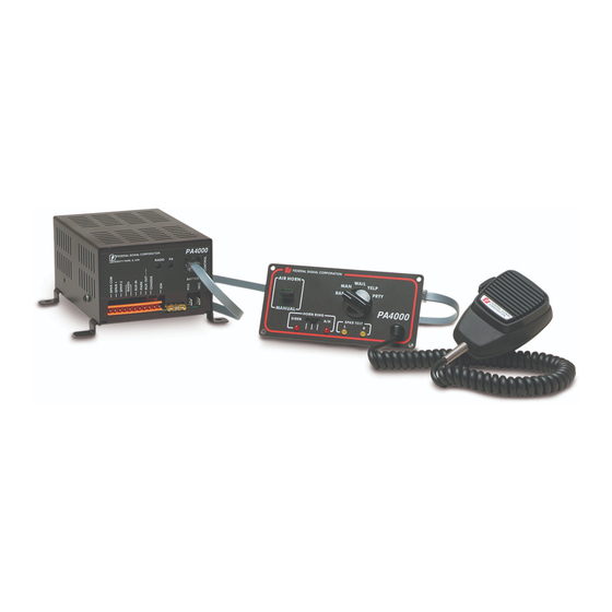
- Page 1 MODEL PA4000 ELECTRONIC SIRENS INSTALLATION, OPERATION, AND SERVICE INSTRUCTIONS 255292 D0 0519...
- Page 2 A copy of this limited warranty can also be obtained by written request to Federal Signal Corporation, 2645 Federal Signal Drive, University Park, IL 60484, email to info@fedsig. com or call +1 708-534-3400.
-
Page 3: Table Of Contents
Contents SECTION I GENERAL DESCRIPTION 4 SECTION II SPECIFICATIONS 5 SECTION III INSTALLATION 6 3-1. UNPACKING ............................................. 8 3-2. AMPLIFIER INSTALLATION ......................................8 3-3. CONTROL HEAD INSTALLATION ....................................8 3-4. ELECTRICAL INSTALLATION ....................................... 9 3-5. INSPECTION AND FINAL INSTALLATION ................................12 SECTION IV OPERATION 13 4-1. - Page 4 • Park-Siren Deactivator can deactivate siren tones when the vehicle is shifted into PARK. The Model PA4000 is designed to drive one or two • A diagnostic capability for speaker testing 100 watt speakers. Using two 100-watt speakers uses two LEDs for visual indication and four will provide maximum traffic clearing power.
- Page 5 SECTION II SPECIFICATIONS Input Voltage 11 Vdc to 16 Vdc Polarity Negative ground electrical systems only Standby Current 250mA (backlighting extinguished) Operating Current (Control Head & Ampl.) 13A ±1A (at 13.6V with 5.5-ohm load) Frequency Range 725 to 1600 Hz (nominal) Cycle Rate Wail- 14 cycles/min.
-
Page 6: Section Iii Installation
SECTION III INSTALLATION SAFETY MESSAGE TO INSTALLERS ELECTRONIC SIRENS damage the components. You should verify or test your combination to make sure the system works together properly and meets federal, state People’s lives depend on your proper installation and local standards or guidelines. and servicing of Federal Signal products. - Page 7 After Installation • Mounting the speakers behind the grille will reduce the sound output and warning • After installation, test the siren and light system effectiveness of the siren system. Before to ensure that it is operating properly. mounting speakers behind the grille, make sure the vehicle operators are trained and understand •...
-
Page 8: Unpacking
UNPACKING thread-forming screws are to be used, drill 3/16" holes at the drill position marks. After unpacking the Model PA4000, examine it Drill 9/32" holes at the position marks if for damage that may have occurred in transit. If the 1/4-20 cap screws, lockwashers and the equipment has been damaged, file a claim nuts will be used. -
Page 9: Electrical Installation
3. Drill four 0.120 diameter (#31 drill) mounting c. If routing the cable requires drilling a hole in sheet metal or other material, drill a 5/8" holes at the marks scribed in step B. hole in the material. Install a 5/8" grommet 4. - Page 10 SHOWN HERE IGNITION SWITCH 290A2697B DASH LIGHT OR IGNITION SWITCH Figure 3-1. PA4000 Wiring. connect user-supplied 18 gauge wires to positions 4 position connector. Connect the other end of the wire to a vehicle circuit that is, depending on the and 5 of the eleven-position connector.
- Page 11 This connector should When making the power connections to the be installed on the mating 4-pin connector (J2) PA4000, each wire must be terminated with an located on the Control Head PC board, and should appropriate 1/4" female, insulated, quick-connect be oriented so that the white wire is closest to terminal.
-
Page 12: Inspection And Final Installation
4. Connect the black wire to the negative battery terminal. A secure mechanical and electrical connection is required. 3-5. INSPECTION AND FINAL INSTALLA- TION 1. Plug the eleven-position connector into the mating connector on the unit, and apply pressure until it locks into place. HIGH CURRENT ARCING: Do not connect this system to the vehicle battery until ALL other electrical connections are made and you have... -
Page 13: Section Iv Operation
SECTION IV OPERATION SAFETY MESSAGE TO OPERATORS OF FEDERAL SIGNAL ELECTRONIC SIRENS AND LIGHT/SOUND SYSTEMS effectiveness of the siren system and may damage the components. You should verify or test your combination to make sure the system People’s lives depend on your proper installation works together properly and meets federal, state and servicing of Federal Signal products. - Page 14 After Installation • Mounting the speakers behind the grille will reduce the sound output and warning • After installation, test the siren and light effectiveness of the siren system. Before system to ensure that it is operating properly. mounting speakers behind the grille, make sure the vehicle operators are trained and understand •...
-
Page 15: General
HORN RING SWITCH All controls utilized during normal operation of The horn ring switch determines the function of the the Model PA4000 are located on the Control Head vehicle horn ring. (see figure 4-1). 1. In the center position, the vehicle’s horn will 4-2. -
Page 16: Aux In Function
Move the shift lever to another position to sound the siren tone. 4-11. PA AND RADIO GAIN ADJUSTMENT The PA4000 comes from the factory with the PA and radio gain set to maximum. To decrease the gain settings, proceed as follows while referring to figure 3-1. -
Page 17: Section V Service And Maintenance
• Electronic repairs must be performed by a Most of the component electronic parts used in qualified and competent electronics technician. the Model PA4000 are standard items that can be Your hearing and the hearing of others, in or obtained from any radio or electronics supply shop. -
Page 18: Siren
Before reinstalling the repaired PA4000, make certain that the speaker(s) is (are) not defective. 5-2. SIREN General... - Page 19 Transistor, TIP35C, NPN, Power Fuse, 20A, 32V 148A142A Lamp, Panel 149A120 LP1, 2 Insulator (Q106, Q109) 235A150A Amplifier Power Circuit Board, PA4000 2001191A-01 (with parts installed) Amplifier Power Circuit Board, PA4000NY 2005002A-02 (with parts installed) Amplifier Logic Circuit Board 2005001B...
Need help?
Do you have a question about the PA4000 and is the answer not in the manual?
Questions and answers