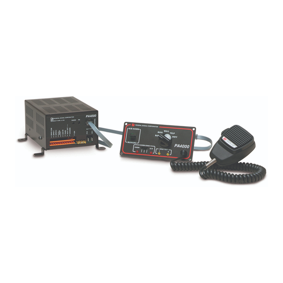
Federal Signal Corporation PA4000 Installation Maintenance And Service Manual
Electronic siren
Hide thumbs
Also See for PA4000:

Related Manuals for Federal Signal Corporation PA4000


Summary of Contents for Federal Signal Corporation PA4000
- Page 1 PA4000 Electronic Siren Installation, Maintenance, and Service Manual 255292 REV. D1 1220 Printed in U.S.A. © Copyright 1994-2020 Federal Signal Corporation...
- Page 2 A copy of this limited warranty can also be obtained by written request to Federal Signal Corporation, 2645 Federal Signal Drive, University Park, IL 60484, email to info@fedsig.com or call +1 708-534-3400.
-
Page 3: Table Of Contents
Table 2 Tap II Functions ..........................17 Table 3 Tap II Functions ........................... 18 Table 4 Replacement parts ..........................19 Figures Figure 1 PA4000 wiring ............................ 13 Figure 2 PA 4000 control head ........................17 Installation, Maintenance, and Service Manual Federal Signal www.fedsig.com... -
Page 4: Safety Messages For Installers And Operators
If drilling must be done near the unit, place an ESD- approved cover over the unit to prevent metal shavings from entering the unit. Inspect the unit after mounting to ensure that there are no shavings present in or near the unit. PA4000 Electronic Siren System Federal Signal www.fedsig.com... - Page 5 Safety Messages for Installers and Operators • Do NOT connect this system to the vehicle battery until ALL other electrical connections are made, mounting of all components is complete, and you have verified that no shorts exist. If wiring is shorted to vehicle frame, high current conductors can cause hazardous sparks, resulting in electrical fires or flying molten metal.
- Page 6 • In order to be an effective warning device, this product produces bright light that can be hazardous to your eyesight when viewed at a close range. Do not stare directly into this lighting product at a close range, or permanent damage to your eyesight may occur. PA4000 Electronic Siren System Federal Signal www.fedsig.com...
- Page 7 Safety Messages for Installers and Operators • It is important that you fully understand how to safely operate this warning system before use. • Operate your vehicle and its light/sound system in accordance with your department’s Standard Operating Procedures. • If a selected function does not perform properly or if any of the lamps remain illuminated when the control is off, disconnect the power connector from the control unit and contact the nearest service center.
-
Page 8: Introduction
PA use. PA and radio volume are preset at the factory for maximum gain. The Model PA4000 is designed to drive one or two 100-watt speakers. Using two 100-watt speakers will provide maximum traffic clearing power. -
Page 9: Installing The Amplifier
Installing the Amplifier Table 1 Specifications Input Voltage 11 Vdc to 16 Vdc Polarity Negative ground electrical systems only Standby Current 250 mA (backlighting extinguished) Operating Current 13 A ±1 A (at 13.6V with 5.5-ohm load) (Control Head & Ampl.) Frequency Range 725 to 1600 Hz (nominal) Cycle Rate... -
Page 10: Installing The Control Head
2. Place the mounting template, supplied in the accessory kit, over the selected mounting location. Scribe a mark for each of the four mounting holes. Also scribe a cut mark along the heavy, dark line on the template. PA4000 Electronic Siren System Federal Signal www.fedsig.com... -
Page 11: Making The Electrical Connections
Making the Electrical Connections DRILLING PRECAUTIONS: Before drilling holes, check the area into which you plan to drill to ensure that you do not damage vehicle components. All drilled holes should be deburred and all sharp edges should be smoothed. 3. -
Page 12: Connecting The Siren
“2” to position 1 of the eleven-position connector. Connect one of the speaker leads marked “1” to position 2 of the eleven- position connector. Connect the other speaker lead marked “1” to position 3 of the eleven position connector. PA4000 Electronic Siren System Federal Signal www.fedsig.com... -
Page 13: Figure 1 Pa4000 Wiring
Connecting the Siren Figure 1 PA4000 wiring CONTROL CABLE PA4000 SPEAKER 11 PIN NO. 1 UNIVERSITY PARK, IL. U.S.A. CONNECTOR RADIO 18 GA. (10) SPEAKER NO. 2 BATTERY WIRE STRIPPING TYPICAL 9 10 11 FUSE BATTERY 2 WAY POS. AND NEG. - Page 14 However, in order to utilize the Tap II and horn ring controlled Air Horn features of the siren, the following procedure must be performed. 1. Locate the wire that connects the vehicle horn ring switch to the horn or horn relay. Cut this wire. PA4000 Electronic Siren System Federal Signal www.fedsig.com...
- Page 15 The Control Head can now be secured to the vehicle dashboard. Amplifier Power Connections When making the power connections to the PA4000, each wire must be terminated with an appropriate 1/4-inch female, insulated, quick-connect terminal. Complete the wiring to the unit as follows: 1.
-
Page 16: Finishing The Installation
After testing is complete, provide a copy of this manual to all operating personnel. Operating the Siren All controls utilized during normal operation of the Model PA4000 are located on the Control Head. See Figure 2. Figure 2 PA 4000 control head... -
Page 17: Table 2 Tap Ii Functions
Operating the Siren Selector Switch The Selector switch is a five-position rotary switch used to select the mode of operation. The following are positions on the Selector switch. • Radio: In this position, incoming radio messages are amplified by the siren and rebroadcast over the outside speaker. -
Page 18: Table 3 Tap Ii Functions
PA and Radio Gain Adjustment The PA4000 comes from the factory with the PA and Radio Gain set to maximum. To decrease the gain settings, proceed as follows while referring to Figure 1 on page 13. - Page 19 Operating the Siren Installation, Maintenance, and Service Manual Federal Signal www.fedsig.com...
-
Page 20: Getting Technical Support And Service
125B437B Fuse, 20A, 32V 148A142A LP1, 2 Lamp, Panel 149A120 Insulator (Q106, Q109) 235A150A Amplifier Power Circuit Board, PA4000 2001191A-01 (with parts installed) Amplifier Power Circuit Board, PA4000NY 2005002A-02 (with parts installed) Amplifier Logic Circuit Board 2005001B (with parts installed) - Page 21 Return Material Authorization (RMA). Obtain a RMA from a local Distributor or Manufacturer’s Representative. Provide a brief explanation of the service requested, or the nature of the malfunction. Address all communications and shipments to the following: Federal Signal Corporation Service Department 2645 Federal Signal Drive University Park, IL 60484-3167...
Need help?
Do you have a question about the PA4000 and is the answer not in the manual?
Questions and answers