
Subscribe to Our Youtube Channel
Related Manuals for Federal Signal Corporation Pathway


Summary of Contents for Federal Signal Corporation Pathway
- Page 1 Pathway ™ Installation and Maintenance Instructions 25500680 REV A2 0523 Printed in U.S.A. © Copyright 2020-222 Federal Signal Corporation...
- Page 2 A copy of this limited warranty can also be obtained by written request to Federal Signal Corporation, 2645 Federal Signal Drive, University Park, IL 60484, email to info@fedsig.com or call +1 708-534-3400.
-
Page 3: Table Of Contents
Siren Specifications ..............................11 Relay Specifications ..............................12 Pathway Kit Contents .............................. 12 Wiring the Unit ..........................14 General Guidelines for Wiring the Pathway on a Vehicle ................14 Overview of the Pathway Connections ......................16 Convergence Network Ports ......................16 Relay Outputs ............................16 General Purpose Inputs........................16... - Page 4 Table 5 PW100R Kit Contents ............................ 13 Table 6 Pathway Switch Default Programming ....................24 ® Table 7 Pathway Button Default Programming ....................24 Table 8 Pathway Input Default Programming .......................25 Table 9 Service Parts ..............................31 Figures Figure 1 100 W Siren Connections ........................... 15 Figure 2 Battery Connections ............................
-
Page 5: Safety Messages For Installers And Operators
Safety Messages for Installers and Operators For your safety, read and understand this manual thoroughly before installing, operating, and servicing the Pathway siren amplifier/relay module. The safety messages presented in this chapter and throughout the manual are reminders to exercise extreme care at all times. Read and understand the safety instructions to installers (doc. - Page 6 • If a vehicle seat is temporarily removed, verify with the vehicle manufacturer if the seat needs to be recalibrated for proper airbag deployment. • Locate the control head so the vehicle, controls, and microphone can be operated safely. Pathway ™ Federal Signal www.fedsig.com...
- Page 7 Safety Messages for Installers and Operators • When drilling into a vehicle structure, ensure that both sides of the surface are clear of anything that could be damaged. All drilled holes should be deburred and all sharp edges should be smoothed. All wires going through drilled holes should be protected by a grommet or convolute/split-loom tubing.
-
Page 8: Safety Messages To Operators Of Sound/Light Systems
Temperature changes and sunlight can cause suction cups to lose holding power. Periodically check the unit to be sure the suction cups have a firm grip on the Pathway ™ Federal Signal www.fedsig.com... - Page 9 Safety Messages for Installers and Operators mounting surface. An improperly secured light could fall off of the vehicle, causing injury and damage. • The holding power of magnetic mounting systems is dependent upon surface finish, surface flatness, and thickness of the steel mounting surface. Therefore, to promote proper magnetic mounting: •...
-
Page 10: Overview
(Self -Contained), in the trunk, or under the seat (remote) of any vehicle with a 12 V or 24 V negative ground system. The Pathway siren uses class D amplifier technology without the need for a large and heavy transformer. The PW100 provides one 100-watt channel. -
Page 11: Programmable Input Circuits
Overview Programmable Input Circuits Pathway has connections for four general-purpose input circuits, plus dedicated inputs for park, horn and igniton. The inputs are most commonly used for switches that send a signal to the siren when a condition in the vehicle changes. -
Page 12: Relay Specifications
Qty. Description Part Number - PW100 100-Watt Siren/Light Controller, Self-Cont 862303655-100 Keypad Legend Stickers 8572294 Bracket, Bail, Pathway, Plastic 862303559 RS485 25 ft (7.62 m) Cable Assembly 1751357-02 Wire Assemby, Relay 17501359 Wire Assembly, I/O 17501360 Cable, USB 2.0, A Male to Mini-B... -
Page 13: Table 5 Pw100R Kit Contents
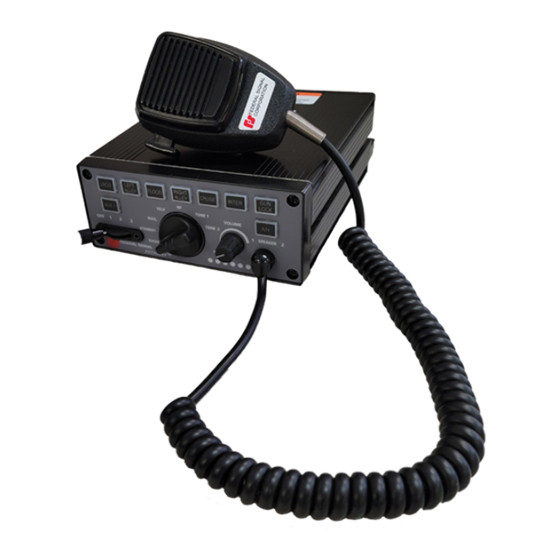
Overview Table 5 PW100R Kit Contents Qty. Description Part Number - PW100R 100-Watt Amplifier, Pathway 862303658-100 Control Head, Remote, Pathway 862303659 Keypad Legend Stickers 8572294 Dynamic Microphone with Mod 258B577-03 Bracket, Bail, Pathway, Plastic 862303559 Bracket, Mtg. Control, Smart 85361065 Cable Assy, RS485, 25ft (7.62 m) -
Page 14: Wiring The Unit
Failure to observe this warning could cause serious injury or death. Before permanently installing the Pathway system, plan all wire routings and select the mounting locations for the siren amplifier/relay module. Read and understand all instructions included with related equipment before installing it. -
Page 15: Figure 1 100 W Siren Connections
Wiring the Unit Figure 1 100 W Siren Connections Ground - Battery + Installation and Maintenance Instructions Federal Signal www.fedsig.com... -
Page 16: Overview Of The Pathway Connections
The Pathway ® has a total of twelve solid-state relay outputs available. Relays 1-8 can each provide up to 5 A switched from the battery terminal on the Pathway. Relays 9-12 can each provide up to 20 mA maximum switched to ground trigger output to another device. -
Page 17: Horn Ring Transfer
9. Connect the other end of the relay coil to the opposite potential of that connected to the switched relay contact terminal in step 7. Speaker Connections The Pathway PW100 is designed to operate with one 11-ohm impedence, 100W speaker. Speaker Diagnostics The Pathway siren is designed to detect speaker faults. -
Page 18: Radio Re-Broadcast
The ignition input is a programmable active high input that can be used to turn on and off the Pathway system. This input can be programmed to keep the system alive for a set time after ignition is removed. By default, this input is set to turn off the system immediately when ignition is removed. -
Page 19: Mounting The Pathway
Mounting the Pathway Mounting the Pathway The next step in the installation after wiring and connecting the system is to permanently mount the siren in the vehicle. Verify that the mounting locations you selected earlier are safe for installing these components. Review the following precautions before mounting the equipment. -
Page 20: Figure 3 Pathway Dimensions
Mounting the Pathway Figure 3 Pathway Dimensions 7.0 in 1.4 in 6.0 in 2.5 in Figure 4 Mounting Hardware Dimensions 0.47 in (1.19 cm) 0.28in (0.71 cm) 4.37 in (11.09 cm) Pathway ™ Federal Signal www.fedsig.com... -
Page 21: Mounting The Siren
Mounting the Pathway Figure 5 Bail Bracket Assembly Mounting the Siren To mount the siren: 1. Use the bracket as a template or use the dimensions shown in Figure 4 to mark the centers of the two mounting holes. 2. Choose a bit appropriate for the installer-supplied mounting hardware and drill the center of the two mounting holes. -
Page 22: Figure 6 Bracket Attached To Back Of Control Head
Mounting the Pathway Figure 6 Bracket Attached to Back of Control Head Figure 7 Brackets Attached to Control Head and Mounting Surface 4. With an 11/64-inch bit, drill two mounting holes at the drill position marks. 5. Secure the mounting bracket to the mounting surface with the #10 thread- forming screws. -
Page 23: Testing The Installation
Test the vehicle only in a controlled environment. After testing is complete, provide a copy of this manual to the instructional staff and all operating personnel. Figure 8 Pathway Default Programming Installation and Maintenance Instructions Federal Signal www.fedsig.com... -
Page 24: Table 6 Pathway ® Switch Default Programming
Priority, dependent on Slide Switch 3 activation Rotary – Tone 2 HI-LO, dependent on Slide Switch 3 activation Turns Off Keypad Backlighting Volume Switch Table 7 Pathway Button Default Programming Button Default Function BTN 1 Step 1 – Left Alley (LB) Step 2 –... -
Page 25: Horn Ring Operation
Testing the Installation Table 8 Pathway Input Default Programming Button Default Function Ignition System Enable Park Siren Mute White Light Cutoff (LB/ILS/CNSM) Horn Ring Siren Tone Override/Control Input 1 Remote SSW1 Activation Input 2 Remote SSW2 Activation Input 3 Remote SSW3 Activation... -
Page 26: Control Head Legends And Safety Messages
Give the operator of the system the card entitled “Safety Message to Operators of Federal Signal Light/Sound Systems” (part no. 256B691). See Figure 10. The operator must read and understand the safety instructions and keep the card in the vehicle for reference. Pathway ™ Federal Signal www.fedsig.com... -
Page 27: Applying The Siren Safety Labels In The Vehicle
Control Head Legends and Safety Messages Applying the Siren Safety Labels in the Vehicle The kit includes a sheet of two labels with siren safety messages (part no. 1612339). See Figure 10. These labels must be installed in the vehicle in which the system is installed. -
Page 28: Safety Messages
Verify or test your combination to make sure the system works together properly and meets both federal, state and local standards or guidelines. Failure to follow all safety precautions and instructions may result in property damage, serious injury, or death. Pathway ™ Federal Signal www.fedsig.com... -
Page 29: Servicing The Unit
Servicing the Unit Servicing the Unit Federal Signal recommends that the siren be returned to your local distributor or Federal Signal for service. External components, such as cabling, are available as replacement parts. (See Table 9.) Except the slide switch in the siren, there are no other user-serviceable parts within the unit. -
Page 30: Figure 12 Slide Switch Replacement
10. Snap the siren bezel to the keypad, connect the ribbon cable and microphone lead to the amp PCBA, and secure the assembly with the four 8-32 shoulder screws. Do not overtighten the screws. Pathway ™ Federal Signal www.fedsig.com... -
Page 31: Ordering Replacement Parts
1-800-264-3578, 7 a.m. to 5 p.m., Monday through Friday (CT) or contact your nearest distributor. Table 9 Service Parts Description Part Number Keypad Legends 8572294 Cable Assembly, RS485, 25-foot 1751357-02 Wire Assembly, Relay, Pathway 17501359 Wire Assembly, I/O, Pathway 17501360 Term, #8, 6AWG 19001363 Slide Switch Assembly 122290 Bezel, Slide Switch... - Page 32 2645 Federal Signal Drive University Park, Illinois 60484-3167 www.fedsig.com Customer Support Police/Fire-EMS: 800-264-3578 • +1 708 534-3400 Work Truck: 800-824-0254 • +1 708 534-3400 Technical Support 800-433-9132 • +1 708 534-3400...
Need help?
Do you have a question about the Pathway and is the answer not in the manual?
Questions and answers