
Related Manuals for Federal Signal Corporation Premium Vision


Summary of Contents for Federal Signal Corporation Premium Vision
- Page 1 Price $15.00 ® PREMIUM VISION WARNING SYSTEM (with Slide Switch Control Head) OPERATION AND CONFIGURATION INSTRUCTIONS...
- Page 3 SECTION I OPERATION SAFETY MESSAGE TO OPERATORS OF FEDERAL SIGNAL LIGHT/SOUND SYSTEMS WARNING • Although your warning system is operating properly, it may not alert everyone. People The lives of people depend on your safe opera- may not hear, see, or heed your warning tion of Federal products.
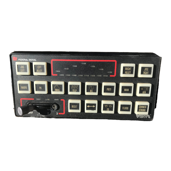
- Page 4 Do not leave the system powered-up The Premium Vision control head is designed to unless the vehicle engine is running. assist the operator’s selection of functions. Each control head switch is recessed and aids guiding the After power is applied, the system will power-up operator’s finger to the switch’s center for activation.
- Page 5 Mode 2 or Mode 3 is selected. NOTE The Premium Vision’s horn ring transfer feature allows activating a light pattern/siren tone associated Operating the foot switch (if installed), or with the vehicle’s horn ring. In this keyboard configu-...
- Page 6 ANY changes to the described keyboard configura- Slide Switch Position 3 (MODE 3). tion. It is YOUR responsibility to understand how Slide switch position 3 activates Mode this system is configured (programmed) to operate. 3. In this keyboard configuration, all seven lights rotate in synchronization at 90 FPM creating a NOTE center-out pattern.
- Page 7 Press switch 5 a fourth time to installer MUST inform you if the system is config- deactivate the SignalMaster directional signal and ured for a common microphone. the switch 5 LED will extinguish. Press switch 10 to activate the PA Switch 6 (TAKE-DOWN).
- Page 8 14. Switch 14 (PRIORITY). 20. Switch 20 (JOG RIGHT). Press switch 14 to select the priority Press switch 20 to manually position siren tone and illuminate the switch 14 LED. Press activated take-down/alley lights for use as a spot- switch 14 again to select no siren tone and extinguish light.
-
Page 9: Section Ii Configuration
CONFIGURATION WARNING Property damage, serious injury, or death to you or others may result if the Premium Vision warning system is improperly configured. Con- figuration, if required, is to be performed at the time of installation. It is NOT intended for operators to “customize”... -
Page 10: Starting Configuration
CONFIGURATION GENERAL Many times, the default just doesn’t meet all the needs for a particular in- stallation. When changes need to be made, the control head is used to reconfigure the system. Since reconfiguration can get some- what complicated, it is best to figure out exactly what needs to be changed be- fore diving into reconfiguration. - Page 11 LEVEL 1 GENERAL Important In LEVEL 1 you have three choices: Note: Always leave the 1. Pressing key 6 will select CLEAR. Slide Switch OFF 2. Pressing key 5 will select Selecting CLEAR or DEFAULT. while programming! DEFAULT will erase all 3.
-
Page 12: Important Notes
LEVEL 2 PROGRAMMING SLIDE HORN RING KEY GENERAL SWITCHES On typical Siren systems that are LEVEL 2 is used to reconfigure indi- equipped with the TAPII function, when vidual keys. Only certain keys are To program the slide switches, simply the Horn is pressed, the Siren changes. - Page 13 LEVEL 2 - KEYS GENERAL PATTERN NUMBER RELAYS In LEVEL 2 - KEYS you can assign To select a pattern number, press keys Press key 19 (RELAY SELECT) until many different functions to a key/switch. 10 through 16 (labeled above as 2 the needed combination of relays are Each key can control: through 8 for convenience) to create...
- Page 14 LEVEL 3 GENERAL NO WHITE LIGHT STANDARD Level 3 configuration is used in areas No White Light makes the pods used If STANDARD is chosen, no special where no white light can shine forward for takedown nonfunctional during pri- functions are activated. Standard is the or a steady red light is needed.
- Page 15 LEVEL 4 GENERAL HORN RING TRANSFER SIREN POWER-UP TONE LEVEL 4 is used to configure the siren Keys 10 through 14 can be configured functions. to turn on automatically during power- The horn ring transfer tone is selected up. Simply turn on the key(s) you wish by pressing key 18.
- Page 16 Loosen the two hexagon head screws CONFIGURATION MODE on the underside of the Amplifier/Relay Unit, near DISABLE/ENABLE. the front edge of the unit. Slide the chassis out of the Disable. case. After the warning system is configured and See the figure below. Solder a jumper fully tested, it may be desirable to disable the con- across J3 on the Amplifier/Relay Unit’s relay circuit figuration mode and prevent reconfiguration by...
- Page 18 2-10...
- Page 19 2-11...
- Page 20 PATTERN PATTERN 175 175 175 175 175 SECONDARY PATTERNS PRIMARY PATTERNS JL JL JL JL JL AUXILIARY UTILITY PATTERNS PATTERNS LEGEND NOTES: ROTATE (nn = SPEED) RA RIGHT ALLEY A. SYNC CENTER OUT. B. SYNC SPECIAL. FLASH TO FRONT LA LEFT ALLEY C.
-
Page 21: Section Iii Microprocessor Installation
Disassemble the Amplifier/Relay Unit 3-2. INSTALLATION. as described in the Service and Maintenance section CAUTION of the Premium Vision Installation and Maintenance The CMOS microprocessors and the Vision’s Instructions (Part No. 255274). circuitry can be destroyed, or damaged, by static discharge. Observe anti-static proce-... - Page 22 IC is facing the same direction as the old one lightbar as described in the Service and Maintenance (toward F1—20-ampere fuse) and that all IC pins are section of the Premium Vision Hardware Installation properly inserted in the socket—not bent under. and Maintenance Instructions (Part No. 255274).
- Page 23 Figure 3-4. Bar Control Microprocessor. cessor IC is facing the same direction as the old one NOTE (toward the seven pod connector cables) and that all IC pins are properly inserted in the socket—not bent If old labels are installed, remove them or under.
- Page 24 255273C REV. C 301 Printed in U.S.A.
Need help?
Do you have a question about the Premium Vision and is the answer not in the manual?
Questions and answers