
Subscribe to Our Youtube Channel
Related Manuals for J&M 275-ST


Summary of Contents for J&M 275-ST
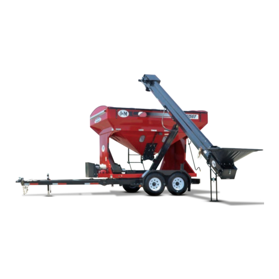
- Page 1 OPERATORS MANUAL 275-ST J. & M. Mfg. Co., Inc. 284 Railroad Street - P.O. Box 547 Fort Recovery, OH 45846 Ph: (419) 375-2376 Fax: (419) 375-2708 www.jm-inc.com...
-
Page 2: Table Of Contents
Table Of Contents 4-6 ........... . General Infortmation 5 . -
Page 4: General Infortmation
General Information TO THE DEALER Read manual instructions and safety rules. Make sure all items on the Dealer’s Pre-Delivery and Delivery Check Lists are completed before releasing equipment to the owner. The dealer must complete the Warranty Registration found on the Dealer Portal website located at dealer.jm-inc.com and return it to J. -
Page 5: Specifications
Specifications 275ST8BC 375ST8BC with 8” Wide Tube Conveyor w/ 8” Tube Conveyor 5’ 4’-10” 2’-10” (Gooseneck Option) 2’-7” (Gooseneck Option) 1’-6” (min) 1’-10” (max) 1’-6” (min) 1’-10” (max) 2’-7” (min) 3’-3” (max) Gooseneck Option 2’-7” (min.) 3’-3” (max.) Gooseneck Option 21’-3”... - Page 6 General Information TO THE OWNER: The purpose of this manual is to assist you in operating and maintaining your seed tender in a safe manner. Read it carefully. It furnishes information and instructions that will help you achieve years of dependable performance and help maintain safe operating conditions.
-
Page 7: Safety Rules
Safety Rules Understand that your safety and the safety of other persons are measured by how you service and operate this machine. Know the positions and functions of all controls before you try to operate them. Make sure to check all controls in a safe area before starting your work. -
Page 8: Decals
Decals * Model 275 Shown Description Part # Stripe Kit Specify Model J&M Oval Decal Medium JM0010179 On/Off Decal JM0014974 Warning, Pinch Point Decal JM0014994 Warning, Moving Parts Decal JM0014993 Warning, Falling/Lowering Decal JM0014992 Warning, Lug Nuts Tight? Decal JM0014996 J&M Oval Tru-Trak Decal JM0037730 Danger, Flowing Grain Traps ST Decal... - Page 9 Decals...
-
Page 10: Operations
1.0 Operations 1.1 Preparing the Towing Vehicle Before towing the Speed Tender, refer to towing vehicle’s owner’s manual for information concerning hitch capacities, hitch adjustments, and tire inflation. Towing vehicle must be equipped with proper electric braking components. NOTE: The Speed Tender is equipped with LED lights. The towing vehicle may require a flasher upgrade for lights to operate properly. - Page 11 1.0 Operations Figure 1.1 1.4 Transporting NOTE: Make sure the jack is in the horizontal position before transporting. NOTE: Check to make sure the boom arm is in the boom rest and the lynch pin is in place with the conveyor ratchet strap securely fastened. NOTE: Make sure that the collapsible hopper is in the up position.
- Page 12 1.0 Operations WARNING: Purge hydraulic system of air before operating Speed Tender to prevent serious injury or death. WARNING: Wear proper hand and eye protection when searching for leaks. Use wood or cardboard instead of hands. Check to make sure all fittings and hardware are in proper operating condition. Replace if worn or broken.
- Page 13 1.0 Operations 1.6 Field Operation WARNING: The Speed Tender must be hooked to the towing vehicle during loading and unloading. Position the Speed Tender next to the planter/drill so the conveyor will reach the planter box. Remove lynch pin from Boom Arm. (Figure 1.3). Start the hydraulic power unit and increase throttle speed.
- Page 14 1.0 Operations Hydraulic Door Wireless Handheld Assembly Remote Control Figure 1.4 Figure 1.5 See Section 4.1 for Remote Options Hopper Up Figure 1.6 Open door on Speed Tender using supplied remote. (Figure 1.4). WARNING: Empty-out the rear compartment first to help prevent the chance of flipping the Speed Tender.
- Page 15 1.0 Operations Position boom above boom rest and lower to allow its full weight on the boom rest. Replace lynch pin in Boom Arm. Make sure that the conveyor hold down ratchet strap is tight enough that the conveyor will not move during transportation.
- Page 16 1.0 Operations Lock collapsible hopper in the up position (Figure 1.6). Position the wagon or bulk seed container over the collapsible hopper. Use the handheld controller or wireless remote to start the conveyor. Fill the Speed Tender to desired level. WARNING: Fill the front compartment first to help prevent the chance of flipping.
- Page 17 1.0 Operations Lower the boom so you can remove the telescoping spout from the discharge end of the conveyor. Undo the conveyor hold down ratchet strap (Figure 1.3). Swing the collapsible hopper end out from under the Speed Tender shell. Place the collapsible hopper in the up position (Figure 1.6) With the discharge end lower than the collapsible hopper end, place the discharge end into a 5 Gal.
- Page 18 1.0 Operations 1.9 Adjusting the Tarp Tension in Hanger Bracket Fully unroll the tarp as shown in Figure 1.11. Remove the two bolts that hold the tarp U-Joint on the splined shaft. Remove the u-joint from the spline shaft. Rotate u-joint and handle three or four spline teeth. NOTE: Clockwise to tighten the tarp or counter-clockwise to loosen it.
-
Page 19: Service
2.0 Service 2.1 Grease Conveyer Bearings Grease the conveyor bearings every 10 hours of operation and before storage. Use only two pumps of grease per bearing (Figure 2.1). NOTE: Over lubrication of these bearings will result in premature failure. NOTE: The conveyor has four bearings that need grease (two at each end). Grease Point Figure 2.1 2.2 Grease Boom Arm... - Page 20 2.0 Service 2.3 Tire Pressure The following is to be used as a general guide for tire inflation. Figures can vary depending on specific brand of tire used. It is im- portant that tires are inspected before and after unit is loaded. Start with the minimum pressure indicated. The tire should stand up with no side wall buckling or distress as tire rolls.
- Page 21 2.0 Service 2.5 Wheel Bearings The wheel bearings need to be cleaned, inspected, and repacked every 12 months or 12,000 miles. Use a number 2 wheel bearing grease to repack the bearings. Bearing Inspection and Service: Jack up Speed Tender. Remove wheel lug-nuts.
- Page 22 2.0 Service 2.6 Hydraulic Power Unit Daily (every 5 hours of use): Check oil level. Inspect for oil leaks and repair as necessary. Check all hoses, fittings, bolts and hardware to make sure that they are secure and properly tightened. Check motor oil level.
- Page 23 2.0 Service Remove Remove Discharge Pan Bearing Mounting Plate Jam Nut Adjustment Bolt Loosen these Figure 2.4 bolts when adjusting belt Conveyer tension. Typical each side. Clean-out Door 2.8 Adjusting Conveyer Belt Tracking Measurments A & B need to be the same. Loosen (Do Not Remove) the 4 bolts on the two bearing mounting plates located at the collapsible hopper end of the conveyor (Figure 2.5).
- Page 24 2.0 Service 2.9 Belt Tensioning NOTE: You need to adjust your belt tension at least once a year. Remove the head pan and head pan gasket (Figure 2.3). Loosen (Do Not Remove) the 4 bolts on the two bearing mounting plates located at the discharge end of the conveyor (Figure 2.3).
- Page 25 2.0 Service How to adjust electric brakes: Park the Speed Tender on firm and level ground. Block the trailer tires on the opposite side securely so that no forward or rearward movement is possible. Jack up the Speed Tender. Secure the trailer on jack stands of adequate capacity front and rear. At the back of the wheel, on the brake backing plate, there is a small rubber plug near the bottom of the backing plate.
- Page 26 2.0 Service Replacing Brake Linings: Remove the brake shoe retract spring. Remove the shoe hold down assembly by holding the back of the pin with one hand and pushing against the spring and twisting with a hold down spring tool until the cup is released. Remove both shoes together leaving the adjuster assembly and spring intact.
- Page 27 2.0 Service Straight Edge Abnormal Wear Normal Wear (Replace) Figure 2.7 Voltage in the system should begin at 0 volts. As the controller bar is slowly actuated, the voltage should gradually increases to about 12 volts. This is referred to as modulation. No modulation means that when the controller begins to apply voltage to brakes it applies an immediate high voltage, which causes the brakes to apply instantaneous maximum power.
- Page 28 2.0 Service Brake Drum Inspection: There are two areas of the brake drum that are subject to wear and require inspection. These two areas are the drum surface where the brake shoes make contact during stopping and the armature surface where the magnet contacts (only in electric brakes). The drum surface should be inspected for excessive wear or heavy scoring.
- Page 29 2.0 Service 2.12 End of the Year Service(Continued) Torque lug-nuts (Section 2.4). Make sure that the tires are properly inflated. Remove all grain from inside the grain tanks. Clean out the Conveyor at the end of every season (Section 1.8). Tension and track the conveyor belt.
- Page 30 2.0 Service 2.14 Troubleshooting Problems Solutions Unit sways during travel a. Check tire pressure. b. Check tow vehicle for loosened hitch parts. c. Check tow vehicle’s hitch height. d. Reduce towing speed. e. Check wheel lug-nuts. f. Check wheel bearings for adjustment (See section 2.5). Tires show excessive wear a.
- Page 31 2.0 Service 2.14 Troubleshooting Problems Solutions Belt has insufficient output speed or R.P.M. - Air in a. Bleed air out of hydraulic system and fill reservoir (See section hydraulic system. 2.6). b. Look for leaking or cracked fittings. Belt has insufficient output speed or R.P.M. - Leak in motor, valve a.
- Page 32 Specifications 2.0 Service 2.15 Bolt Torque Specifications Standard Dry Torque in Foot-Pounds Bolt Dia. Pitch (in.) (threads/ Grade 0-1-2 Grade 3 Grade 5 Grade 6 Grade 7 Grade 8 inch) 74,000 psi 100,000 psi 120,000 psi 133,000 psi 133,000 psi 150,000 psi Low Carbon Med.
-
Page 34: Hydraulics
3.0 Hydraulics 3.1 Hydraulic Schematic Tank /Hydraulic Power Unit Rear Door Front Door Motor Aluminum Valve Block Conv. Drive Pump Conv. Return Tank Swing Cyl. Boom Cyl. - Page 35 3.0 Hydraulics t# Description Part. No. 1/2" male JIC x 1/2" male NPT ; 90 degree elbow JM0033727 1/2" male JIC x 1/2" male NPT ; 90 degree elbow, extra long JM0033728 3/8" male NPT x 3/8" female NPT, swivel, 0.042 orifice; straight JM0033729 3/8"...
- Page 36 5 - Function Manifold Valve Schematic (Aluminum) 2015 & Newer 3.2 Aluminum Valve Block Connector Letter Function Boom swing front (optional) Boom swing rear (optional) Boom Up Boom Down Rear door up (optional) Front door down (optional) Power Front door up (optional) Rear door down (optional) Pump In Conveyor Start...
-
Page 37: Wiring
4.0 Wiring 4.1 Remote Options Controllers/Remotes Description Item # Description Part # Qty. Handheld Controller 1 JM0014991 Conveyor Swing Front Wireless Remote w/ Receiver JM0015005 Conveyor Swing Rear Boom Up BOOM Boom Down REAR SWING FRONT Rear Door Up Front Door Down Red - Power FRONT REAR... -
Page 38: Auto-Scale Shut-Off
Specifications Auto Scale Shutoff In order for the Auto Dispense function to work, the Speed Tender must be equipped with a factory installed and powered on Weigh-Tronix 640XL In order for the Auto Dispense function to work, the Speed Tender must scale indicator with the J&M Mega Remote with Auto Dispense as shown mote be equipped with a factory installed and powered on Weigh-Tronix 640XL... - Page 39 4.0 Wiring 4.2 Light Wiring Harnesses- JM0033700 Main Harness 419-475 To Rear Top To A-Frame or Harness Goosneck Harness To Right Front To Rear Brake Light Marker Right Round Lights Red Marker To Electric Harness Light To Stationary To Scale Box Valve Bank Control Box (optional)
- Page 40 Specifications 4.0 Wiring Rear Top Harness (JM0019964) White 100” 7” 7” 2” 7” 7” To Rear Top Marker Lights Front Harness (JM0019963) White 3” 30” 8” 3” To Front Top Harness 43” 65” To Front Lower Marker Light To Front Lower Marker Light 7-Way Trailer Connection (JM0019962 A-Frame) (JM0019961 Gooseneck)
- Page 41 4.0 Wiring Flood Light Switch Harness (JM0034135) Onboard Controller 60” 2” 2” Black White To Flood Light Harness White To Flood Light Harness Black Flood Light Harness (JM0019965) To Tank Flood Light 170” Black To Conveyor White Flood Light 402” Black White Flood...
-
Page 42: Repair Parts
Repair Parts Description Page Ladder Parts Scale Parts Chassis Parts 5.10 A-Frame Parts 5.11 5.12 Boom Arm Parts Conveyor 46-47 Swing Cylinder Parts Hydraulic Door Parts Shell Parts 5.10 Roll Tarp Parts... - Page 43 5.0 Parts 5.1 Ladder Parts Description Part. No. 5/16”-18 Gr5 Z Centerlock Hex Nut JM0002143 Gas Spring JM0001961 3/8”-16 x 1” Gr5 Z SF Hex Bolt JM0002092 3/8”-16 Gr5 Z SF Hex Nut JM0002152 3/8”-16 x 1” Gr5 Z Hex Bolt JM0001592 3/8”...
- Page 44 Specifications 5.0 Parts 5.2 Scale Parts Description Part. No. Scale Box Display JM0007293 3/8"-16 x 1-1/2" Gr5 Z Hex Bolt JM0001659 3/8" USS Flat Washer JM0003061 Scale Box Door JM0002944 Chrome T-Handle Non-Locking JM0001911 Scale Box JM0009961 3/8"-16 Gr5 Z Centerlock Hex Nut JM0001512 1/4"-20 x 3/4"...
- Page 45 5.0 Parts 5.3 Chassis Parts Description Part. No. Description Part. No. Boom Rest Weldment JM0005876 3/8"-16 Gr5 Z Centerlock Hex Nut JM0001512 1/2"-13 x 1-3/4" Gr5 Z Hex Bolt JM0002101 3/8" USS Flat Washer JM0003061 1/2"-13 Gr5 Z SF Hex Nut JM0002153 J&M Mud Flap JM0001910...
- Page 46 5.0 Parts 5.4 Axle Parts Description Part. No. Dexter No. 085-001-00 Rubber Plug for Dust Cap JM0039538 006-053-00 9/16”-18 Lugnut JM0008525 019-002-00 Cotter Pin 1/8” x 1-3/4” JM0039545 031-017-02 14125A Roller Bearing JM0039542 363906 (Alko) Stud 9/16”-18 x 2.81” JM0020625 031-030-01 25520 Race JM0018102...
-
Page 47: A-Frame Parts
5.0 Parts 5.5 A-Frame Parts Description Part. No. 5/8"-11 x 2" Gr8 Z Hex Bolt JM0001771 5/8"-11 Gr5 Z Centerlock Hex Nut JM0002146 A-Frame Weldment JM0002481 Jack Stand w/ Lynch Pin JM0001480 1/4" x 3/4" Self Tapping Screw JM0001570 Break Away Switch JM0001843 2-5/16"... - Page 48 5.0 Parts 5.6 Boom Arm Parts Description Part. No. 1-1/4"-12 PN Gr5 Hex Jam Nut JM0001606 Upper Boom Pivot Weldment JM0001605 1-1/4" Bronze Bushing (1 1/2" OD) JM0002248 8"-22' Tube Conveyor Boom Arm JM0027453 3/8"-16 x 1" Gr8 Z SF Hex Bolt JM0001509 Vertical Axis Boom Pin Weldment JM0002238...
-
Page 49: Conveyor
5.0 Parts 5.7 Conveyor t# Description Part. No. 2" Wide Ratchet 10,000 lb JM0003084 #8-32 x 1/2" Slotted Hex Washer Head Machine Screw JM0012333 #8-32 Z Nylon Locking Hex Nut JM0012334 Leg Spring Plunger JM0002789 Conveyor Hopper Support Tube - 275/375ST JM0002780 Seed Tender Hopper Tarp JM0008383... - Page 50 5.0 Parts 5.8 Conveyor Idler End Components Description Part. No. 3/8”-16 Gr5 Z SF Hex Nut JM0002152 3/8”-16 x 1” Gr5 Z Carriage Bolt JM0001632 Conveyor Guard Weldment JM0002466 3/8”-16 Gr5 Z Centerlock Hex Nut JM0001512 1-1/4” Diameter 2 Bolt Flange Bearing JM0001811 Bearing Mount JM0002199...
-
Page 51: Swing Cylinder Parts
5.0 Parts 5.9 Swing Cylinder Parts Description Part. No. 1” x 2-1/4” Pin w/ Cotter Pin JM0010201 Dual Swing Linkage JM0002260 Single Swing Linkage JM0002252 1” x 3.4” Clevis Pin w/ Cotter Pins JM0001816 Cylinder 3” x 14” w/Pins and Clips and Fittings JM0002261 5.10 Hydraulic Door Parts Description... - Page 52 5.0 Parts 5.11 Shell Parts Description Part. No. Description Part. No. Amber Round Light Assembly JM0001908 11b Speed Tender-Honda GX340 Engine JM0001749 Amber Round Light JM0001895 1/4"-20 Gr5 Z SF Hex Nut JM0001630 Round Light Grommet JM0001902 1/4"-20 x 1" Gr5 Z Hex Bolt JM0002095 Red Round Light Assembly JM0001905...
-
Page 53: Roll Tarp Parts
5.0 Parts Specifications 5.12 Roll Tarp Parts Description Part. No. Description Part. No. 3/8"-16 Gr5 Z Centerlock Hex Nut JM0001512 14 3/8"-16 Gr5 Z SF Hex Nut JM0002152 1/4"-20 Gr5 Z Centerlock Hex Nut JM0001505 15 Tie-Down Tube JM0007469 Roll Pipe Weldment JM0007041 16 Tarp Stop JM0002448... -
Page 54: Available Options
5.0 Parts 5.13 Available Options Description Product # Gooseneck Frame and Hitch Assembly in place of standard A-Frame 375ST-GNO 5th Wheel Hitch on Gooseneck Frame Assembly in place of standard Truck Hitch. Includes 7-way Flat to 375ST-5WH 7-Way Round Adapter Trailer Mount Kit in place of Standard Chassis (Deluxe All-Function Wireless Remote Control Option Recommended) 275ST-TM Electric Roll Tarp in place of Standard Roll Tarp RT-375ST-E... - Page 55 6.0 Aftermarket Installation Instructions 6.1 Scales Installation Note: For Scale parts see Section 5.3 Slide the weigh bar into the scale mount. Making sure that the Weigh bar sticker is facing up (Figure 6.1). Insert two 3/8”-16 x 3-1/2” Grade 5 Zinc Hex Bolt (#1) into scale mount and tighten using 3/8”-16 Centerlock Hex Nut (#2) (Figure 6.1).
- Page 56 6.0 Aftermarket Installation Instructions Remove the four 1 3/8” grommets located in the four chassis holes (Figure 6.3) Slide one grommet on to each of the weigh bar wires of B,C, and D. (Figure 6.3) NOTE: Spray grommets with a lubricant spray for ease of installation. Route each wire from B,C and D so they exit chassis hole (Figure 6.3).
- Page 57 6.0 Aftermarket Installation Instructions 6.2 Talc Applicator Parts Description Part. No. Tank Saddle JM0029359 3/8"-16 x 1" Gr5 Z SF Hex Bolt JM0002092 3/8"-16 Gr5 Z SF Hex Nut JM0002152 3/8"-16 Gr5 Z Centerlock Hex Nut JM0001512 1/4"-20 x 3/4" Gr5 Z SF Hex Bolt JM0001642 Black UHMW JM0029386...
- Page 58 6.0 Aftermarket Installation Instructions Specifications Back Plate Print Power Cord Weigh Bar Plugin Plugin Plugins (Optional) Wireless Receiver Plugin Figure 6.6 Figure 6.7 NOTES...
Need help?
Do you have a question about the 275-ST and is the answer not in the manual?
Questions and answers