MR TAPCON 230 basic Operating Instructions Manual
Voltage regulator
Hide thumbs
Also See for TAPCON 230 basic:
- Operating instructions manual (130 pages) ,
- Operating instructions manual (172 pages) ,
- Operating instructions manual (108 pages)
Table of Contents
Advertisement
Quick Links
Advertisement
Table of Contents

Related Manuals for MR TAPCON 230 basic


Summary of Contents for MR TAPCON 230 basic
- Page 1 Voltage Regulator ® TAPCON 230 basic Operating Instructions 2117246/05 EN...
- Page 2 © All rights reserved by Maschinenfabrik Reinhausen Dissemination and reproduction of this document and use and disclosure of its content are strictly prohibited unless expressly permitted. Infringements will result in liability for compensation. All rights reserved in the event of the granting of patents, utility models or designs.
-
Page 3: Table Of Contents
Table of contents Table of contents Introduction......................... 7 Manufacturer............................ 7 Subject to change without notice ...................... 7 Completeness............................. 7 Safekeeping............................ 7 Notation conventions .......................... 7 1.5.1 Hazard communication system .......................... 8 1.5.2 Information system.............................. 9 1.5.3 Instruction system .............................. 9 1.5.4 Typographic conventions ............................ 10 Safety.......................... - Page 4 Table of contents 5.1.3 Markings................................ 24 Transportation, receipt and handling of shipments................ 24 Storage of shipments........................ 26 Mounting ........................... 27 Preparation ............................ 27 Mounting device.......................... 27 6.2.1 Flush panel mounting............................ 29 6.2.2 Wall mounting with mounting brackets........................ 30 6.2.3 Cap rail mounting .............................. 31 6.2.4 Wall mounting .............................. 32 6.2.5...
- Page 5 Table of contents 8.2.6 Activating/deactivating the automatic key lock.................... 53 8.2.7 "Function monitoring" message for monitoring messages <30 V................ 54 8.2.8 Setting motor runtime monitoring ........................ 55 8.2.9 Activate manual mode/auto mode........................ 57 8.2.10 Activating Local/Remote ............................. 58 8.2.11 Setting the COM1 password .......................... 58 8.2.12 Setting the password duration.......................... 59 NORMset ............................
- Page 6 Table of contents 8.10.2 Displaying measured values .......................... 93 8.10.3 Display calculated values............................ 94 8.10.4 Carrying out LED test............................ 95 8.10.5 Displaying status of the MIO card ........................ 95 8.10.6 Resetting parameters............................ 96 8.10.7 Displaying memory overview .......................... 97 8.10.8 Displaying event overview........................... 97 Fault elimination ....................... 98 No regulation in AUTO mode......................
-
Page 7: Introduction
1 Introduction 1 Introduction This technical file contains detailed descriptions on the safe and proper in- stallation, connection, commissioning and monitoring of the product. It also includes safety instructions and general information about the prod- uct. This technical file is intended solely for specially trained and authorized per- sonnel. -
Page 8: Hazard Communication System
1 Introduction 1.5.1 Hazard communication system Warnings in this technical file are displayed as follows. 1.5.1.1 Warning relating to section Warnings relating to sections refer to entire chapters or sections, sub-sec- tions or several paragraphs within this technical file. Warnings relating to sections use the following format: Type of danger! WARNING... -
Page 9: Information System
1 Introduction Pictograms warn of dangers: Pictogram Meaning Warning of a danger point Warning of dangerous electrical voltage Warning of combustible substances Warning of danger of tipping Table 2: Pictograms used in warning notices 1.5.2 Information system Information is designed to simplify and improve understanding of particular procedures. -
Page 10: Typographic Conventions
1 Introduction Multi-step instructions Instructions which consist of several process steps are structured as follows: Aim of action ü Requirements (optional). 1. Step 1. ð Result of step (optional). 2. Step 2. ð Result of step (optional). ð Result of action (optional). 1.5.4 Typographic conventions The following typographic conventions are used in this technical file: Typographic convention... -
Page 11: Safety
2 Safety 2 Safety 2.1 General safety information The technical file contains detailed descriptions on the safe and proper in- stallation, connection, commissioning and monitoring of the product. ▪ Read this technical file through carefully to familiarize yourself with the product. -
Page 12: Operator's Duty Of Care
2 Safety 2.5 Operator's duty of care To prevent accidents, disruptions and damage as well as unacceptable ad- verse effects on the environment, those responsible for transport, installa- tion, operation, maintenance and disposal of the product or parts of the prod- uct must ensure the following: ▪... -
Page 13: It Security
3 IT security 3 IT security Observe the following recommendations to operate the product safely. General ▪ Ensure that only authorized personnel have access to the device. Use the device door lock for this purpose. ▪ Only use the device within an ESP (electronic security perimeter). Do not connect the device to the Internet in an unprotected state. -
Page 14: Product Description
4 Product description 4 Product description This chapter contains an overview of the design and function of the product. 4.1 Scope of delivery The following components are included in the delivery: ▪ Voltage Regulator TAPCON® 230 basic ▪ Folder with all device documentation ▪... -
Page 15: Function Description Of The Voltage Regulation
4 Product description Figure 4: Cap rail clip Please note the following: ▪ Check the shipment for completeness on the basis of the shipping docu- ments. ▪ Store the parts in a dry place until installation. 4.2 Function description of the voltage regulation The TAPCON®... -
Page 16: Performance Features
4 Product description Summer Winter Regulation section regulating transformer Load profile of grid Automatic voltage regulator TAPCON® 230 basic Desired value Line voltage Control variable for line voltage Measurement transformer Inputs, digital and analog Figure 5: Overview of voltage regulation 4.3 Performance features The TAPCON®... -
Page 17: Operating Modes
4 Product description 4.4 Operating modes The device can be operated in the following operating modes: Auto mode (AUTO) In auto mode, the voltage is automatically controlled in accordance with the set parameters. You cannot change further device settings in auto mode. There is no active management by a higher level control system in this oper- ating mode. -
Page 18: Name Plate
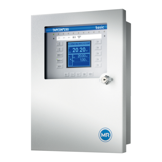
4 Product description Figure 6: Hardware 1 Operating panel with display and 3 Door LEDs 2 Door lock 4 Metric cable glands 4.5.1 Name plate The name plate is on the outside of the device: Figure 7: Name plate ® TAPCON 230 basic 2117246/05 EN Maschinenfabrik Reinhausen GmbH 2019... -
Page 19: Operating Controls
4 Product description 4.5.2 Operating controls The device has 15 pushbuttons. The illustration below is an overview of all the device's operating controls. Figure 8: Operating controls RAISE key: Sends control command for raise tap-change to the motor- drive unit in manual mode. LOWER key: Sends control command for lower tap-change to the motor- drive unit in manual mode. -
Page 20: Display Elements
4 Product description MENU key: Select main menu. F1 to F5 function keys: Select functions displayed on the screen. 4.5.3 Display elements The device has a graphics display and 15 LEDs , which indicate the various operating statuses or events. Figure 9: Indicator elements 1 Operating status LED, green 9 LED 3, function can be freely as-... - Page 21 4 Product description Display Figure 10: Display 1 Status line 6 Time bar for delay time T1 2 Measured voltage U 7 Highlighting for measured voltage 3 Reference voltage U 8 Highlighting for reference voltage 9 Remaining delay time T1 Other measured values (use to switch between them) 5 Bandwidth (upper and lower limit) Other measured values In auto mode and manual mode the measured value display...
-
Page 22: Serial Interface
4 Product description Unit Measured value Phase Phase angle Cosine Table 5: Measured value display Status line Current messages and events are displayed in the status line . You can find more information about messages and events in the Messages chapter. 4.5.4 Serial interface The parameters for the device can be set using a PC. -
Page 23: Mio Card Module
4 Product description 4.5.5 MIO card module The device has an internal module. Carry out wiring in accordance with the supplied connection diagram. Figure 12: MIO card 1 Relay outputs (terminal X4) 4 Current transformer connection (terminal X1) 2 Signal inputs (terminal X4) 5 Voltage transformer connection and network connection (terminal 3 Relay outputs (terminal X3) -
Page 24: Packaging, Transport And Storage
5 Packaging, transport and storage 5 Packaging, transport and storage 5.1 Packaging 5.1.1 Purpose The packaging is designed to protect the packaged goods during transport, loading and unloading as well as periods of storage in such a way that no (detrimental) changes occur. - Page 25 5 Packaging, transport and storage If a crate tips over, falls from a certain height (e.g. when slings tear) or is subject to an unbroken fall, damage must be expected regardless of the weight. Every delivered shipment must be checked for the following by the recipient before acceptance (acknowledgment of receipt): ▪...
-
Page 26: Storage Of Shipments
5 Packaging, transport and storage 5.3 Storage of shipments When selecting and setting up the storage location, ensure the following: ▪ Protect stored goods against moisture (flooding, water from melting snow and ice), dirt, pests such as rats, mice, termites and so on, and against unauthorized access. -
Page 27: Mounting
6 Mounting 6 Mounting This chapter describes how to correctly install and connect the device. Ob- serve the connection diagrams provided. Electric shock! DANGER Risk of fatal injury due to electrical voltage. Always observe the following safety regulations when working in or on electrical equipment. ►... - Page 28 6 Mounting ▪ Wall mounting with mounting brackets ▪ Rail mounting (optional) Preparing for mounting Before commencing mounting, the two mounting brackets back on the rear of the device must be removed and the cable gland plate taken off. To do so, proceed as follows: 1.
-
Page 29: Flush Panel Mounting
6 Mounting 6.2.1 Flush panel mounting For flush panel mounting , the device is inserted through a cutout in the con- trol panel and fixed to the control panel or control cabinet from behind using the mounting brackets. The diagram below shows the dimensions required for the control panel cutout. -
Page 30: Wall Mounting With Mounting Brackets
6 Mounting Proceed with wiring as shown in the connection diagram and as described in the Connecting device [►Section 6.3, Page 34] section. 6.2.2 Wall mounting with mounting brackets As an alternative to mounting the device directly on the wall, it can be fixed to the wall using the mounting brackets supplied. -
Page 31: Cap Rail Mounting
6 Mounting Proceed with wiring as shown in the connection diagram and as described in the Connecting device [►Section 6.3, Page 34] section. 6.2.3 Cap rail mounting As an option, the device can be fitted with a cap rail clip (aluminum extrusion with wire spring integrated at center). -
Page 32: Wall Mounting
6 Mounting 6.2.4 Wall mounting For wall mounting, , the device is fixed directly to the wall. Drill 4 holes, each 5.5 mm in diameter, in the wall as shown in the drilling template below. Figure 20: Drilling template for wall mounting To mount the device directly on the wall, proceed as follows: ü... -
Page 33: Removing The Door
6 Mounting 6.2.5 Removing the door When the door is fitted, the device satisfies protection category IP54. The door may be removed if the device is used solely in a dry atmosphere pro- tected from environmental influences. The device then satisfies protection category IP21. -
Page 34: Connecting Device
6 Mounting 3. Hook the cover strip in the upper and lower suspension mount and fasten it with the provided raised countersunk head screws. Figure 24: Fasten covering strip ð The door is removed and the exposed attachment points for the door are covered. -
Page 35: Cable Recommendation
6 Mounting 2. Crimp stranded wires with wire end sleeves. 6.3.1 Cable recommendation Please note the following recommendation from Maschinenfabrik Rein- hausen when wiring the device. Excessive line capacitance can prevent the relay contacts from breaking the contact current. In control circuits operated with alternating current, take into account the effect of the line capacitance of long control cables on the func- tion of the relay contacts. -
Page 36: Electromagnetic Compatibility
6 Mounting ▪ Be aware of sharp edges because they can damage the fiber-optic cable's coating during laying or can place mechanical loads on the coating later ▪ Provide a sufficient cable reserve near distributor cabinets. Lay the re- serve such that the fiber-optic cable is neither bent nor twisted when tight- ened. - Page 37 6 Mounting Figure 25: Recommended wiring 1 Cable duct for lines causing inter- 3 Cable duct for lines susceptible to ference interference 2 Line causing interference (e.g. 4 Line susceptible to interference power line) (e.g. signal line) ▪ Short-circuit and ground reserve lines. ▪...
- Page 38 6 Mounting Figure 26: Recommended connection of the shielding 1 Connection of the shielding via a 2 Full-surface connection of the single conductor shielding 6.3.3.3 Wiring requirement in control cabinet Note the following when wiring the control cabinet: ▪ The control cabinet where the device will be installed must be prepared in accordance with EMC requirements: –...
-
Page 39: Connecting Cables To The System Periphery
6 Mounting Figure 27: Ground strap connection Ground connection for wiring inside the device The diagram below shows the ground connection for wiring inside the de- vice. Figure 28: Grounding inside the device 6.3.4 Connecting cables to the system periphery To obtain a better overview when connecting cables, only use as many leads as necessary. -
Page 40: Supplying The Voltage Regulator Using Auxiliary Voltage
6 Mounting To connect cables to the system periphery, proceed as follows: ü Use only the specified cables for wiring. Note the cable recommendation. ► Connect the lines to be wired to the device to the system periphery as shown in the connection diagrams supplied. 6.3.5 Supplying the voltage regulator using auxiliary voltage The device is normally supplied by the voltage transformer. -
Page 41: Checking Functional Reliability
Check the following: ▪ Once you have connected the device to the grid, the screen displays the MR logo and then the operating screen. ▪ The green Operating display LED top left on the device's front panel lights The device is fully mounted and can be configured. The actions required for this are described in the following chapter. -
Page 42: Commissioning
7 Commissioning 7 Commissioning You need to set several parameters and perform function tests before com- missioning the device. These are described in the following sections. Damage to device and system periphery NOTICE An incorrectly connected device can lead to damages in the device and sys- tem periphery. -
Page 43: Setting The Language
7 Commissioning 7.2.1 Setting the language You can use this parameter to set the display language for the device. The following languages are available: English Italian German Portuguese French Russian Spanish To set the language, proceed as follows: > Configuration > General. -
Page 44: Function Tests
7 Commissioning 2. Set the bandwidth [►Section 8.4.3.2, Page 66]. 3. Set delay time T1 [►Section 8.4.4, Page 66]. Setting line drop compensation (optional) If you need line drop compensation, you must set all important parameters for this: 1. Select the LDC compensation method [►Section 8.6.1, Page 76]. 2. -
Page 45: Checking Additional Functions
7 Commissioning 7. Set bandwidth depending on step voltage [►Section 8.4.3, Page 65]. 8. Set delay time T1 to 20 seconds [►Section 8.4.4, Page 66]. 9. Set control response T1 to linear [►Section 8.4.5, Page 67]. 10. Press to raise the on-load tap-changer 1 step. 11. - Page 46 7 Commissioning Checking undervoltage blocking U< 1. Press to select manual mode. 2. Set undervoltage U < [%] to 85 %. 3. Set the U< blocking parameter to On [►Section , Page 71]. 4. Set desired value 1 such that the measured voltage Uactual is below the undervoltage U<...
- Page 47 7 Commissioning Checking desired value 2 and desired value 3 1. Press to select manual mode. 2. Set desired value 2 to the value you want. 3. Apply voltage L+ to terminal X4:17 desired value 2 (see connection dia- gram). 4. Press until the main screen is displayed. ð...
- Page 48 7 Commissioning 11. Set the line drop compensation Ur and line drop compensation Ux parameters to the desired operating values. ð The function test for line drop compensation is complete. Checking Z compensation If you want to use Z compensation, you need to run this function test. A load current of ≥ 10 % of the nominal transformer current is needed for the follow- ing function test .
-
Page 49: Operation
8 Operation 8 Operation This chapter describes all the functions and setting options for the device. 8.1 Key lock The device is equipped with a key lock to prevent unintentional operation. You can only set or change the parameters when the key lock is deactivated in manual mode. -
Page 50: Setting The Baud Rate
8 Operation To set the device ID, proceed as follows: > Configuration > General > Press until the desired pa- rameter is displayed. ð Regulator ID. 2. Press to change the first digit. ð If you wish to enter a multi-digit sequence, proceed to step 3. If you do not wish to enter additional digits, proceed to step 7. - Page 51 8 Operation Switching pulse in normal If you set the switching pulse time to 1.5 seconds for example, after the set mode delay time T1 or delay time T2 there will be a switching pulse of 1.5 sec- onds The waiting time between 2 consecutive switching pulses corresponds to the set delay time T1 or delay time T2 Figure 32: Switching pulse time in normal mode 1 Set delay time T1 or T2...
-
Page 52: Setting Operations Counter
8 Operation Switching pulse for rapid If you set the raise switching pulse time or lower switching pulse time to return control 1.5 seconds, for example , the next earliest switching pulse occurs in rapid return control mode 1.5 seconds after the previous switching pulse ended. -
Page 53: Dimming Display
8 Operation To set the operations counter, proceed as follows: > Configuration > General > Press until the desired pa- rameter is displayed. ð Operations counter. 2. Press to highlight a digit. ð The desired position is highlighted and the value can be changed. 3. -
Page 54: Function Monitoring" Message For Monitoring Messages <30 V
8 Operation To set the automatic key lock, proceed as follows: > Configuration > General > Press until the desired pa- rameter is displayed. ð Key lock 2. Press to select On or Off. 3. Press ð Automatic key lock is set. 8.2.7 "Function monitoring"... -
Page 55: Setting Motor Runtime Monitoring
8 Operation To set the delay time for the Function monitoring message, proceed as fol- lows: > Configuration > General > Press until the desired pa- rameter is displayed. ð Delay function monitoring 2. Press to increase the value or to reduce it. - Page 56 8 Operation Wiring control input/output If you want to monitor the motor runtime, the device and motor-drive unit relay must be connected and parameterized as shown below. Figure 35: Wiring for motor runtime monitoring 1 Motor running control input I/O 3 Motor protective switch tripped GPO output relay (optional) 2 Motor protective switch triggered 4 Motor runtime exceeded GPO out-...
-
Page 57: Activate Manual Mode/Auto Mode
8 Operation To set the motor runtime, proceed as follows: > Configuration > General > Press until the desired pa- rameter is displayed. ð Motor runtime. 2. Press to highlight the position. ð The desired position is highlighted and the value can be changed. 3. -
Page 58: Activating Local/Remote
8 Operation 8.2.10 Activating Local/Remote This parameter can be used to activate the Local or Remote operation modes. This parameter has the same functions as the keys. Parameter Function Local You can operate the device using the control panel. Remote You can operate the device using an external con- trol level. -
Page 59: Setting The Password Duration
8 Operation Proceed as follows to set the COM1 password: > Configuration > General > Press until the desired pa- rameter is displayed. ð COM1 password. 2. Enter the current COM1 password. Press to change a charac- ter and to select the next character. 3. - Page 60 8 Operation ▪ Primary voltage ▪ Secondary voltage Line drop compensation cannot be performed in NORMset mode. Set the following parameters to operate the device in NORMset mode. Activating/deactivating NORMset You can use this parameter to activate NORMset mode. A manual tap-change operation is required to activate NORMset. This is how the voltage regulator determines the bandwidth required.
-
Page 61: Control Parameters
8 Operation To set the secondary voltage, proceed as follows: > NORMset > Press until the desired parameter is dis- played. ð Secondary voltage. 2. Press to increase the value or to reduce it. 3. Press ð The secondary voltage is set. Setting desired value 1 With this parameter, you can set the desired value for automatic voltage reg- ulation. - Page 62 8 Operation Behavior only with delay time T1 If the measured voltage U is within the set bandwidth , no control actual commands are issued to the motor-drive unit for the tap-change operation. Control commands will also not be issued to the motor-drive unit if the mea- sured voltage returns to the tolerance bandwidth within the set delay time .
-
Page 63: Setting Desired Value 1
8 Operation delay time T2 starts once delay time T1 is complete. Once delay time T2 is complete, a control impulse is again output to the motor-drive unit for the tap change to return to the tolerance bandwidth. Figure 39: Behavior of the regulation function with delay times T1 and T2 1 + B %: Upper limit 4 Set delay times T1 and T2. -
Page 64: Selecting A Desired Value
8 Operation Options for setting the The device provides the following ways of changing the desired voltage desired values value during operation: ▪ Using the control parameters menu item via the operating screen ▪ Using binary inputs ▪ Using control system protocols if a communication card is ready for opera- tion Reference of kV and V for Desired values set in kV refer to the primary voltage of the voltage trans-... -
Page 65: Bandwidth
8 Operation 8.4.3 Bandwidth You can use this parameter to set the maximum permissible deviation in measured voltage U . The deviation relates to the activated desired value. The following sections describe how you determine and set the bandwidth required. 8.4.3.1 Determining bandwidth In order to set the correct value, the transformer's step voltage and nominal voltage must be known. -
Page 66: Setting Delay Time T1
8 Operation 8.4.3.2 Setting the bandwidth To enter the determined bandwidth, proceed as follows: > Parameter > Control parameter > Press until the de- sired parameter is displayed. 2. Press to highlight the position. ð The desired position is highlighted and the value can be changed. 3. -
Page 67: Setting Control Response T1
8 Operation To set the delay time T1, proceed as follows: > Parameter > Control parameter > Press until the de- sired parameter is displayed. 2. Press to highlight the position. ð The desired position is highlighted and the value can be changed. 3. -
Page 68: Setting Delay Time T2
8 Operation To set the control response T1, proceed as follows: > Parameter > Control parameter > Press until the de- sired parameter is displayed. 2. Press to set the response you want. 3. Press ð The control response T1 is set. 8.4.6 Setting delay time T2 With this parameter, you can set delay time T2. -
Page 69: Limit Values
8 Operation 8.5 Limit values In the Limit values menu item, you can set all the parameters needed for limit value monitoring as relative or absolute values. You can set three limit values: ▪ Undervoltage U< ▪ Overvoltage U> ▪ Overcurrent I> Limit value monitoring is used to reduce damage to the system periphery. - Page 70 8 Operation Behavior If the measured voltage U falls below the set limit value , the red actual LED U< lights up . The switching pulses to the motor-drive unit are blocked at the same time provided you have activated the blocking undervoltage U< parameter.
- Page 71 8 Operation To set the limit value for undervoltage U< as %, proceed as follows: > Control parameter > Limit values > Press until the desired parameter is displayed. ð U< Undervoltage (%) 2. Press to increase the value or to reduce it.
-
Page 72: Setting Overvoltage Monitoring U
8 Operation To activate/deactivate the undervoltage blocking, proceed as follows: > Control parameter > Limit values > Press until the desired parameter is displayed. ð U< blocking. 2. Press for On setting or for Off setting. 3. Press ð Undervoltage blocking is activated/deactivated. Activating/deactivating message for voltages below 30 V You can use this parameter to set whether the Undervoltage message is to be suppressed at a measured value of less than 30 V. - Page 73 8 Operation Response to high-speed If the measured voltage U exceeds the set limit value , the red LED U> actual return and associated signaling relay activate. The Overvoltage U> message ap- pears in the display. At the same time, the high-speed return function is acti- vated without delay time T1.
-
Page 74: Setting Overcurrent Monitoring I
8 Operation Setting overvoltage U> as % The limit value is entered as a relative value (%) of the set desired value. To set the limit value, proceed as follows: > Control parameter > Limit values > Press until the desired parameter is displayed. -
Page 75: Set Undercurrent Monitoring I
8 Operation Setting overcurrent I> as % To set the limit value I> overcurrent for overcurrent blocking, proceed as fol- lows: > Control parameter > Limit values > Press until the desired parameter is displayed. ð Overcurrent I> 2. Press to increase the value or to reduce it. -
Page 76: Activate/Deactivate Active Power Monitoring
8 Operation Activating/deactivating I< undercurrent blocking To activate/deactivate undercurrent monitoring, proceed as follows: > Control parameter > Limit values > Press until the desired parameter is displayed. ð Blocking undercurrent I>. 2. Press to activate (ON)/deactivate (OFF) undercurrent block- ing. 3. - Page 77 8 Operation To set R&X compensation correctly, you need to calculate the ohmic and in- ductive voltage drop in V with reference to the secondary side of the voltage transformer. You also need to correctly set the transformer circuit used. Figure 46: Equivalent circuit Figure 47: Phasor diagram You can calculate the ohmic and inductive voltage drop using the following...
- Page 78 8 Operation Current transformer ratio Voltage transformer ratio Ohmic resistance load in Ω/km per phase Inductive resistance load in Ω/km per phase Length of line in km Nominal current factor Selecting the line drop compensation To select the line drop compensation, proceed as follows: ►...
- Page 79 8 Operation 8.6.1.2 Setting the inductive voltage drop Ux You can use this parameter to set the inductive voltage drop (inductive resis- tance load). The compensation effect can be rotated by 180° in the display using a plus or minus sign. If you do not want to use line drop compensation, you have to set the value 0.0 V.
- Page 80 8 Operation To use Z compensation, you need to calculate the increase in voltage (ΔU) taking the current into account. Use the following formula for this purpose: ∆U Voltage increase I Load current in A Transformer voltage with cur- Nominal current of current-trans- rent I former connection in A (1 A;...
-
Page 81: Transformer Data
8 Operation To set the current dependent voltage increase, proceed as follows: ü Select Z compensation. > Parameter > Compensation > Press until the desired parameter is displayed. ð Z compensation. 2. Press to increase the value or to reduce it. 3. -
Page 82: Setting The Primary Transformer Voltage
8 Operation ▪ Secondary current (current transformer connection) ▪ Transformer circuit The measured values displayed for the device are influenced by the settings for the above parameters. Note the table below. Parameter set Measured value display Primary Secondary Primary cur- Trans- Voltage (main Current (main... -
Page 83: Setting Primary Transformer Current
8 Operation To set the secondary transformer voltage, proceed as follows: > Configuration > Transformer data > Press until the desired parameter is displayed. ð Secondary voltage. 2. Press to highlight the position. ð The desired position is highlighted and the value can be changed. 3. -
Page 84: Setting The Current Transformer Connection
8 Operation 8.7.4 Setting the current transformer connection This parameter can be used to set the current transformer connection. This setting is needed for the device to display the correct secondary current in the info screen. If you select the "Unknown" option, the percentage of current (with reference to the current transformer connection used) is displayed in the info screen. - Page 85 8 Operation Circuit A: 1-phase measurement in 1-phase grid TAPCON® 230 Figure 52: Phase difference 0 1PH ▪ The voltage transformer VT is connected to the outer conductor and neu- tral conductor. ▪ The current transformer CT is looped into the outer conductor. ▪...
- Page 86 8 Operation Circuit C: TAPCON® 230 Figure 54: Phase difference 0 3PH ▪ The voltage transformer VT is connected to the outer conductors L1 and ▪ The current transformer CT1 is looped into the outer conductor L1 and CT2 into the outer conductor L2. ▪...
- Page 87 8 Operation Circuit E TAPCON® 230 Figure 56: Phase difference 30 3PH ▪ The voltage transformer VT is connected to the outer conductors L1 and ▪ The current transformer CT is looped into the outer conductor L2. ▪ The current I is ahead of voltage U by 30°.
-
Page 88: Configurable Inputs And Outputs
8 Operation To set the phase difference for the transformer circuit, proceed as follows: > Configuration > Transformer data > Press until the desired parameter is displayed. ð Transformer circuit. 2. Press to select the required phase difference. 3. Press ð... - Page 89 8 Operation MPS tripped Input for MPS tripped feedback. MD in progr. Input for MD in progr. feedback. DVL 2 Activate desired value level 2 DVL 3 Activate desired value level 3 Blk U raise Block tap-change operations (raise). Blk U low. Block tap-change operations (lower).
-
Page 90: Linking Outputs With Functions
8 Operation 8.8.2 Linking outputs with functions You can assign one of the following functions to the digital outputs (GPO 1 and 2): Function Description No function selected Local/Rem. Message: Local control/remote control Undervoltage Message: Undervoltage blocking Overvoltage Message: Overvoltage blocking Undercurrent Message: Undercurrent blocking Overcurrent... -
Page 91: Led Selection
You can use labeling strips to label the LED. Depending on your device configuration, the following parameters can be used by MR for special functions. In this case, these parameters are pre-as- signed. You may not be able to view or freely assign these parameters. - Page 92 8 Operation Assigning function To assign a function to an LED, proceed as follows: > Configuration > LED selection > Press until the de- sired parameter is displayed. 2. Press to select the option you want. 3. Press ð The function is assigned. All additional LEDs can be assigned as described previously.
-
Page 93: Information About Device
8 Operation 8.10 Information about device 8.10.1 Displaying info screen The info screen displays the following information: Figure 58: Info screen 1 Type designation 4 Additional cards 2 Software version 5 RAM memory 3 Serial number To display the info screen, proceed as follows: ►... -
Page 94: Display Calculated Values
8 Operation The following measured values can be displayed: Figure 59: Measured values 1 Voltage U in V or kV 3 Frequency f in Hz 2 Current I in % or A 4 Measurement performance PMeas in % or MW To display the measured values, proceed as follows: ►... -
Page 95: Carrying Out Led Test
8 Operation To display the calculated values, proceed as follows: ► > Info > Press until the desired display appears. ð Calculated values 8.10.4 Carrying out LED test You can check whether the LEDs are functioning properly. To do this, press the relevant function key to illuminate an LED: LED no. -
Page 96: Resetting Parameters
8 Operation Digital inputs The status of the optocoupler inputs is shown in the "MIO card digital inputs" display. As soon as a continuous signal is present at the input, status 1 is displayed. 0 indicates no signal at the input. Proceed as follows to display the status: ►... -
Page 97: Displaying Memory Overview
8 Operation 8.10.7 Displaying memory overview The memory overview can be used to display various database entries with the relevant number of data records. The information is not relevant for oper- ation. It is only needed for service checks. The following information is dis- played: ▪... -
Page 98: Fault Elimination
9 Fault elimination 9 Fault elimination This chapter describes how to rectify simple operating faults. 9.1 No regulation in AUTO mode Characteristics/detail Cause Remedy Device control commands have LOCAL/REMOTE switch in motor- Check operating mode. Correct if necessary. no effect. drive unit switched to LOCAL. -
Page 99: Man-Machine Interface
9 Fault elimination 9.3 Man-machine interface Characteristics/detail Cause Remedy Keys REMOTE operating mode active Press to activate LOCAL mode. ▪ MANUAL/AUTO operating and LED in key illuminated. mode cannot be changed Keys Parameter error Reset parameters to factory settings. ▪ LEDs in keys not illuminated. -
Page 100: Customized Gpis/Gpos
9 Fault elimination Characteristics/detail Cause Remedy Measured current Transmission ratio not correctly Correct parameterization. parameterized. ▪ Measured value too high. Incorrect input connected. Remove short-circuiting jumper. ▪ Measured value too low. Phase angle Fault in external transformer cir- Check transformer circuit. cuit. -
Page 101: Other Faults
9 Fault elimination Characteristics/detail Cause Remedy Relays chatter Supply voltage too low Check the supply voltage High EMC load Use shielded cables or external filters Poor grounding Check protective ground Table 30: General faults 9.7 Other faults If you cannot resolve a problem, please contact Maschinenfabrik Rein- hausen. -
Page 102: Messages
10 Messages 10 Messages Event (yellow/ Event message Remark red) Undervoltage Message is displayed in the event of undervoltage. Set the Undervoltage U< [►Section , Page 69] parameter. Overvoltage Message is displayed in the event of overvoltage. Set the Overvoltage U> [►Section , Page 72] parameter. Overcurrent Message is displayed in the event of overcurrent. - Page 103 10 Messages Event (yellow/ Event message Remark red) Blocking: Raise blocked because Message is displayed if raise is blocked because the cor- tap position limit reached or ex- responding tap position limit has been reached or ex- ceeded ceeded. Yellow Tap position limit reached or ex- Message is displayed if the set tap position limit has been ceeded...
-
Page 104: Disposal
11 Disposal 11 Disposal Observe the national requirements applicable in the country of use. ® TAPCON 230 basic 2117246/05 EN Maschinenfabrik Reinhausen GmbH 2019... -
Page 105: Overview Of Parameters
12 Overview of parameters 12 Overview of parameters This section contains an overview of the relevant menus and parameters. The availability of individual parameters varies depending on your device function. Parameter Setting range Factory setting Current setting NORMset Normset activation On/Off Desired value 1 49 to 140 V... - Page 106 12 Overview of parameters Parameter Setting range Factory setting Current setting Configuration > Transformer data Primary voltage 0...9999 kV 0 kV Secondary voltage 57 to 123 V 100.0 V Primary current 0...10000 A 0 a Current transformer connection Unknown; 1 A; 5 A Unknown Transformer circuit See [►Section 8.7.5, 0 1PH Page 84] Display kV / V...
- Page 107 12 Overview of parameters Parameter Setting range Factory setting Current setting LED1 See [►Section 8.9, Page GPI 1 LED2 GPI 2 LED3 yellow LED3 green LED4 yellow LED4 red Info Info Measured values Calculated values LED test MIO inputs MIO outputs Default parameter Memory overview Event overview Table 32: Overview of parameters...
-
Page 108: Technical Data
13 Technical data 13 Technical data 13.1 Display elements Display LCD, monochrome, graphics-capable 128 x 128 pixels LEDs 15 LEDs for operation display and mes- sages of which 4 LEDs are freely pro- grammable (2x yellow, 1x yellow/green, 1x yellow/red) Table 33: Display elements 13.2 Electrical data Permissible voltage range... - Page 109 13 Technical data Figure 61: Front view and side view Figure 62: View from above with installed door Figure 63: View from below without door ® Maschinenfabrik Reinhausen GmbH 2019 2117246/05 EN TAPCON 230 basic...
-
Page 110: Ambient Conditions
13 Technical data 13.4 Ambient conditions Operating temperature -25°C...+70°C Storage temperature -40°C...+85°C Table 36: Ambient conditions 13.5 Electrical safety IEC 61010-1 Safety requirements for electrical mea- surement and control and regulation IEC 61010-2-030 equipment and laboratory instruments IEC 61010-2-201 ▪ Protection class 1 ▪... -
Page 111: Environmental Durability Tests
13 Technical data 13.7 Environmental durability tests DIN EN 60529 Determination of protection class for "protection against contact, ingress of foreign objects and water for electrical equipment" Level IP54 IEC 60068-2-1 Dry cold - 25 °C / 16 hours IEC 60068-2-2 Dry heat + 70 °C / 16 hours IEC 60068-2-3 Constant moist heat + 40 °C / 93% / 21... -
Page 112: Glossary
Glossary Glossary Electromagnetic compatibility Light-emitting diode General Purpose Input Maschinenfabrik Reinhausen GmbH General Purpose Output Raise/lower Line drop compensation ® TAPCON 230 basic 2117246/05 EN Maschinenfabrik Reinhausen GmbH 2019... -
Page 113: List Of Key Words
List of key words List of key words Auxiliary supply 40 Factory setting 96, 105 Language 43 Fiber-optic cable LED selection 91 Information about laying 35 Limit value flush panel mounting 29 Limit value monitoring 69 Bandwidth 65 Function monitoring Overvoltage U>... - Page 114 List of key words Parameter Transformer V< also below 30 V 72 Bandwidth 65 Primary current 83 High-speed return 74 Transformer data 81 Overcurrent blocking 74 Current transformer connection Wall mounting 30, 32 Phase difference 84 84 Wiring 34, 40 Primary voltage 60 Primary voltage...
- Page 116 Maschinenfabrik Reinhausen GmbH Falkensteinstrasse 8 93059 Regensburg +49 (0)941 4090-0 +49(0)941 4090-7001 sales@reinhausen.com www.reinhausen.com ® 2117246/05 EN - TAPCON 230 basic - - 08/19 - Maschinenfabrik Reinhausen GmbH 2019 THE POWER BEHIND POWER.
Need help?
Do you have a question about the TAPCON 230 basic and is the answer not in the manual?
Questions and answers