MR TAPCON 230 Quick Reference Manual
Voltage regulator
Hide thumbs
Also See for TAPCON 230:
- Quick manual (34 pages) ,
- Operating instructions manual (130 pages)
Table of Contents
Advertisement
Quick Links
Advertisement
Table of Contents

Related Manuals for MR TAPCON 230


Summary of Contents for MR TAPCON 230
- Page 1 ® Voltage Regulator TAPCON 230 basic Quick reference guide 2117248/02...
- Page 2 © 2012 All rights reserved by Maschinenfabrik Reinhausen Copying and distribution of this document and the utilization and communication of its contents are strictly prohibited unless expressly authorized. Offenders will be held liable for the payment of damages. All rights reserved in the event of the grant of a patent, utility model or ornamental design registration.
- Page 3 Introduction This technical file contains information for quickly starting up the voltage regulator. It does not pro-vide comprehensive operating instructions. This technical file is intended solely for specially trained and authorized personnel. Manufacturer The voltage regulator is manufactured by: Maschinenfabrik Reinhausen GmbH Falkensteinstraße 8 93059 Regensburg, Germany Tel.: (+49) 9 41/40 90-0...
-
Page 4: Supporting Documents
Supporting documents The installation and commissioning instructions, the operating instructions and the accompanying connec- tion diagrams also apply in addition to this technical file. All documents form part of the scope of delivery. In addition, generally applicable statutory and other binding regulations in European and national legisla- tion and the regulations for accident prevention and environmental protection in force in the country of use... - Page 5 Safety This technical file does not replace the Operating Instructions for the voltage regulator. The quick refer- ence guide contains information that will provide a rapid introduction to operating the voltage regulator. • For detailed operation and safety information please read carefully through the voltage regulator operating instructions.
-
Page 7: Product Description
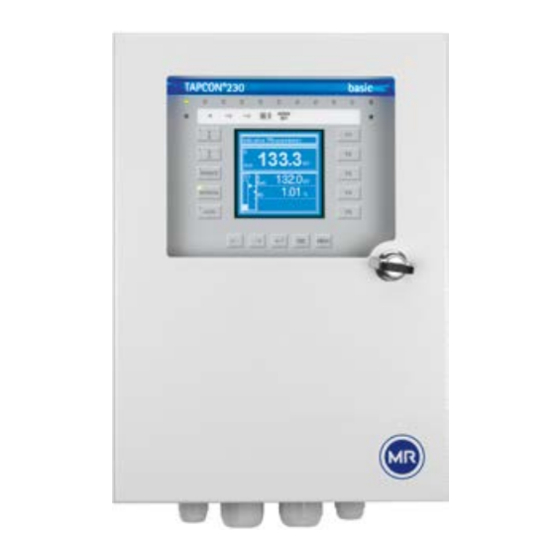
Product description Description of the front panel ® Figure 1 TAPCON 230 front panel LEDs 1...10 Setting options for display contrast Labeling strip for LEDs F1...F5: Function and menu selection keys © Maschinenfabrik Reinhausen 2012... - Page 8 Display 128X128 LCD module negative blue, LED back- ground white Menu selection Escape Accept entry Switching windows within a menu level Parametering interface COM 1 (RS232) Automatic voltage regulation (with auto mode LED green) Manual mode (with manual control LED green) Remote control (with Local/Remote LED green) Control for RAISE/LOWER Status LED...
-
Page 9: Description Of The Display
Description of the display Figure 2 Main screen Status line Actual value display in V/kV Desired value display in V/kV Control deviation Time bar Desired value deviation trend © Maschinenfabrik Reinhausen 2012... -
Page 10: Description Of Key Functions
Description of key functions RAISE In manual mode the motor-drive unit can be oper- ated directly using the RAISE key. LOWER In manual mode the motor-drive unit can be oper- ated directly using the LOWER key. REMOTE Activates the "Remote" operating mode. In this case, manual operation of the RAISE, LOWER, MANUAL and AUTO keys is disabled. - Page 11 F1...F5 The function keys are menu selection keys. They are also used to scroll through the menu sub- groups and input masks. © Maschinenfabrik Reinhausen 2012...
-
Page 13: Functions And Settings
Functions and settings This chapter provides a short summary of all the func- tions and possible settings of the voltage regulator. Please refer to the voltage regulator operating instruc- tions for detailed information on each of the functions and settings. Before carrying out the parameterization, proceed as follows: 1. - Page 14 NORMset The NORMset mode enables easy and user-friendly commissioning of the voltage regulator with a limited set of parameters. For switching to the NORMset mode, the following additional parameters must be set: • Desired value 1 • Primary voltage • Secondary voltage 4.2.1 Activating NORMset...
- Page 15 4.2.2 Setting desired value 1 Setting range Step size Fact. settings 49 V...140 V 0.1 V 100 V Table 1 Setting range for desired value 1 in V Setting range Step size Fact. settings 0 kV...9999 kV 1 kV 1 kV 0 kV...999.9 kV 0.1 kV 0 kV...99.99 kV...
-
Page 16: Control Parameters
Control parameters 4.3.1 Setting desired value Setting range Step size Fact. settings 49 V...140 V 0.1 V 100 V Table 3 Setting range for desired value in V Setting range Step size Fact. settings 0 kV...9999 kV 1 kV 1 kV 0 kV...999.9 kV 0.1 kV 0 kV...99.99 kV... - Page 17 4.3.2 Selecting desired value "Select desired value" is used to define an active desired value on the screen menu. > (Control Parameters) > (Voltage Regulation) > <03> Select Desired Value. 2. Press to select an active desired value. 3. Press to save the setting.
- Page 18 4.3.3 Setting the bandwidth Calculation of the bandwidth in accordance with the following formula: [ ±B % ] ≥ 0.6 · · 100 % Setting range: Setting range Step size Fact. settings 0.5 %...9 % 0.1 % Table 5 Setting range for bandwidth >...
- Page 19 4.3.4 Setting delay time T1 Setting range Step size Fact. settings 0 s...600 s 40 s Table 6 Setting range for delay time T1 > (Control Parameters) > (Voltage Regulation) > <05> Delay Time T1. 2. Press in order to highlight the position. 3.
- Page 20 4.3.5 Setting the control response T1 (linear/integral) Linear: With "Linear Time" the regulator responds with a con- stant delay time which is independent of the control deviation. Integral: The delay time decreases depending on the relation- ship of the control deviation to the set tolerance band- width B, to a minimum of 1 second.
- Page 21 4.3.6 Activating delay time T2 The delay time T2 only comes into effect when more than one tap-change operation is necessary and the first tap-change operation (end of T1) has already taken place. > (Control Parameters) > (Voltage Regulation) > ...
- Page 22 4.3.7 Setting delay time T2 In general, the delay time T2 should be greater than the pulse duration and the maximum operating time of the motor-drive unit. This applies to continuous set- tings in particular. Setting range Step size Fact. settings 1 s...10 s 0.1 s 10 s...
-
Page 23: Displaying The Info Screen
Displaying the info screen Information on the device can be viewed here. The fol- lowing information is displayed: • Device model • Firmware version number • Serial number • • Additional cards > (Info) <00> Info By pressing , the following infor- mation is also displayed: •... - Page 24 • Memory overview (<07> 7x • Event overview (8x © Maschinenfabrik Reinhausen 2012...
- Page 26 2117248/02 EN • 03/12 Maschinenfabrik Reinhausen GmbH Fon: +49 (0)941 40 90-0 Falkensteinstraße 8 Fax: +49 (0)941 40 90-7001 93059 Regensburg E-Mail: sales@reinhausen.com Internet: www.reinhausen.com...
Need help?
Do you have a question about the TAPCON 230 and is the answer not in the manual?
Questions and answers