Table of Contents
Advertisement
Quick Links
Advertisement
Table of Contents

Related Manuals for MR TAPCON 230 Expert


Summary of Contents for MR TAPCON 230 Expert
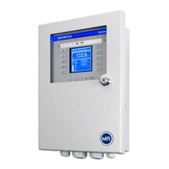
- Page 1 Voltage regulator ® TAPCON 230 Expert Operating instructions 7817454/02 EN...
- Page 2 © All rights reserved by Maschinenfabrik Reinhausen Dissemination and reproduction of this document and use and disclosure of its content are strictly prohibited unless expressly permitted. Infringements will result in liability for compensation. All rights reserved in the event of the granting of patents, utility models or designs.
-
Page 3: Table Of Contents
Table of contents Table of contents Introduction......................... 7 Manufacturer............................ 7 Completeness............................. 7 Safekeeping............................ 7 Notation conventions .......................... 7 1.4.1 Hazard communication system .......................... 7 1.4.2 Information system.............................. 9 1.4.3 Instruction system .............................. 9 1.4.4 Typographic conventions ............................ 10 Safety.......................... 11 Appropriate use .......................... 11 Inappropriate use.......................... - Page 4 Table of contents 4.5.6 Connection diagram and grounding screw...................... 26 4.5.7 Visualization ................................ 27 Packaging, transport and storage .................. 33 Suitability, structure and production .................... 33 Markings ............................ 33 Transportation, receipt and handling of shipments................ 33 Storage of shipments........................ 34 Mounting ........................... 35 Preparation ............................
- Page 5 Table of contents Operation........................... 67 System.............................. 67 9.1.1 General ................................ 67 9.1.2 Configuring the network ............................ 69 9.1.3 Setting the device time............................ 70 9.1.4 Setting the screensaver ............................ 71 9.1.5 Configuring syslog............................... 72 9.1.6 SCADA................................ 74 9.1.7 Linking signals and events .......................... 80 9.1.8 Configuring analog inputs ........................... 83 9.1.9 Configuring digital inputs and outputs ......................... 85 9.1.10...
- Page 6 Table of contents Fault elimination ...................... 141 11.1 General faults .......................... 141 11.2 No regulation in AUTO mode...................... 141 11.3 Unwanted on-load tap-change operation.................. 142 11.4 Human-machine interface....................... 142 11.5 Incorrect measured values ...................... 142 11.6 Parallel operation faults ........................ 143 11.7 Tap position capture incorrect ......................
-
Page 7: Introduction
Download the operating instruc- tions from the device. The operating instructions are also available on the Maschinenfabrik Reinhausen GmbH website and in the MR Customer Portal. 1.4 Notation conventions 1.4.1 Hazard communication system Warnings in this technical file are displayed as follows. - Page 8 1 Introduction 1.4.1.1 Warning relating to section Warnings relating to sections refer to entire chapters or sections, sub-sec- tions or several paragraphs within this technical file. Warnings relating to sections use the following format: Type of danger! WARNING Source of the danger and outcome. ►...
-
Page 9: Information System
1 Introduction Pictograms warn of dangers: Pictogram Definition Warning of a danger point Warning of dangerous electrical voltage Warning of combustible substances Warning of danger of tipping Warning of danger of crushing Table 2: Pictograms used in warning notices 1.4.2 Information system Information is designed to simplify and improve understanding of particular procedures. -
Page 10: Typographic Conventions
1 Introduction Aim of action ü Requirements (optional). ► Step 1 of 1. ð Result of step (optional). ð Result of action (optional). Multi-step instructions Instructions which consist of several process steps are structured as follows: Aim of action ü Requirements (optional). 1. -
Page 11: Safety
2 Safety 2 Safety ▪ Read this technical file through to familiarize yourself with the product. ▪ This technical file is a part of the product. ▪ Read and observe the safety instructions provided in this chapter. ▪ Read and observe the warnings in this technical file in order to avoid func- tion-related dangers. -
Page 12: Inappropriate Use
2 Safety 2.2 Inappropriate use Use is considered to be inappropriate if the product is used other than as de- scribed in the Intended use section. In addition, observe the following: ▪ The product is not a protective device. Do not use it to handle safety-re- lated functions. - Page 13 2 Safety Invisible laser radiation Looking directly into the beam or the reflected beam can cause eye damage. The beam is emitted at the optical connections or at the end of the fiber-optic cables connected to them on the assemblies. Read the chapter "Technical Data"...
-
Page 14: Personnel Qualification
2 Safety Ambient conditions To ensure reliable and safe operation, the product must only be operated under the ambient conditions specified in the technical data. ▪ Observe the specified operating conditions and requirements for the in- stallation location. Modifications and conversions Unauthorized or inappropriate changes to the product may lead to personal injury, material damage and operational faults. -
Page 15: Personal Protective Equipment
2 Safety Operator The operator uses and operates the product in line with this technical file. The operating company provides the operator with instruction and training on the specific tasks and the associated potential dangers arising from im- proper handling. Technical Service We strongly recommend having maintenance, repairs and retrofitting carried out by our Technical Service department. -
Page 16: Security
3 IT security 3 IT security Observe the following recommendations to operate the product safely. 3.1 General ▪ Ensure that only authorized personnel have access to the device. ▪ Only use the device within an ESP (electronic security perimeter). Do not connect the device to the Internet in an unprotected state. -
Page 17: Communication Interfaces
Default setting; if you have modified the port for the control system proto- col, only the set port is open. Port is closed if you activate the device's SSL encryption. SSH is disabled when MR service access is disabled. 3.5 Encryption standards The device supports the following TLS versions: ▪... - Page 18 3 IT security The device uses the following cipher suites for a TLS-secured connection: Key exchange Authentication Encryption Key length Operating Hash func- mode tion ECDHE WITH SHA265 ECDHE ECDSA SHA256 ECDH SHA256 SHA384 Table 6: Cipher suite The device uses the SHA512 hash function to save passwords. ®...
-
Page 19: Product Description
4 Product description 4 Product description 4.1 Scope of delivery Check the shipment for completeness based on the shipping documents. ▪ Voltage regulator ▪ RJ45 patch cables ▪ Shield clamps ▪ Plug connectors ▪ Tension clamps ▪ Technical documents ▪ Additional nameplate ▪... -
Page 20: Performance Features
4 Product description Summer Winter Control path Regulating transformer Automatic voltage regulator Load profile of the grid Desired value Line voltage Control variable Line voltage Measurement transformer Inputs Digital and analog Automatic voltage regulator SCADA Such as for parallel operation of up to 16 transformers Long-distance communication and control center Figure 2: Overview of voltage regulation... -
Page 21: Operating Modes
4 Product description – Reactive power monitoring – Power factor monitoring ▪ Display of all measured values such as voltage, current, active power, ap- parent power and reactive power ▪ Tap position capture – Via BCD code – Via dual code –... -
Page 22: Design
4 Product description Remote mode (REMOTE) In remote mode, you can make entries and issue commands using digital in- puts. AVR AUTO AVR MANUAL LOCAL REMOTE LOCAL REMOTE Automatic regulation Tap-change operation via operating controls Tap-change operation via inputs Tap-change operation via SCADA Value adjustment via SCADA... -
Page 23: Leds
4 Product description 8 ENTER key Confirm selection/save modified parame- ters 9 LEFT cursor Navigate to the left in the menu 10 RIGHT cursor Navigate to the right in the menu 11 BACK key Exit the current menu. Return to the pre- vious menu level Only possible in manual mode. -
Page 24: Connections And Fuses
4 Product description 4.5.3 Connections and fuses The connections are located on the rear of the device. You will find more in- formation on the connections in the Technical data [►Section 13, Page 147] section. Figure 5: Rear 1 F2 Internal fuse for the 2 X9 Power supply power supply... -
Page 25: Nameplate
4 Product description Connections and terminals Figure 6: Connections/terminals 1 COM-X6 CAN bus/SCADA 2 COM-X5 Interface for patch cable for interface RS485/re- SCADA via fiber-optic cable sistor contact series 3 COM-X4 Fiber-optic cable 4 COM-X3 SCADA interface RS232 (SFP cage for the SFP module) 5 COM-X2 Interface for visual- 6 COM-X1... -
Page 26: Safety Markings
4 Product description 4.5.5 Safety markings Warning of a danger point. Read the information given in the product oper- ating instructions. 4.5.6 Connection diagram and grounding screw Figure 8: Connection diagram/grounding screw 1 Grounding screw 2 Connection diagram ® TAPCON 230 Expert 7817454/02 EN Maschinenfabrik Reinhausen GmbH 2021... -
Page 27: Visualization
4 Product description 4.5.7 Visualization 4.5.7.1 Main screen Home Measured values Communication Transformer name Home 101.5 V Position Events 20 s 100.4 V Voltage 100.0 V 0.3% Information Current 40 mA 98.5 V Power factor Change Reboot admin 2020-04-15 10:08 Settings Figure 9: Home 1 Secondary navigation or naviga- 2 Primary navigation tion path 3 Status bar... - Page 28 4 Product description Measured values/display Transformer name Position Measured values Communication Voltage 100.4 V Transformer name Home 101.5 V Position 0.3% Events Current 40 mA 20 s 100.4 V Voltage 100.0 V 0.3% Power factor Information Current 40 mA 98.5 V Power factor Change Reboot admin 2020-04-15 10:08 Settings Figure 10: Measured values 1 Transformer name (can be edited)
- Page 29 4 Product description 4.5.7.2 Operating concept You can operate the device using the controls on the front panel or using the web-based Intuitive Control Interface visualization on a PC. The scope of function and structure of both options is virtually identical. User rights and user roles The device is equipped with a rights system and a roles system.
- Page 30 4 Product description 5. Select Time. In these operating instructions, the path for navigating to a parameter is al- ways shown in an abridged form: Go to Settings > Parameters > System > Time synchronization. Setting parameters There are various ways to configure the settings, depending on the parame- ter.
- Page 31 4 Product description Entering text 1. Use to select the text box and press ð If operating via the front panel, the keyboard appears. Figure 13: Entering text 2. Enter the desired text and confirm with 3. Press the Accept button to save the modified parameter. Parameter search You can use the quick search function in the parameter menu to search for a parameter.
- Page 32 4 Product description Expert mode The device has an expert mode for entering the parameters. You can enter the parameters directly on the overview screen of the respective menu in this mode. Figure 15: Expert mode To activate the expert mode, proceed as follows: 1.
-
Page 33: Packaging, Transport And Storage
5 Packaging, transport and storage 5 Packaging, transport and storage 5.1 Suitability, structure and production The goods are packaged in a sturdy cardboard box. This ensures that the shipment is secure when in the intended transportation position and that none of its parts touch the loading surface of the means of transport or touch the ground after unloading. -
Page 34: Storage Of Shipments
5 Packaging, transport and storage Visible damage If external transport damage is detected on receipt of the shipment, proceed as follows: ▪ Immediately record the transport damage found in the shipping docu- ments and have this countersigned by the carrier. ▪... -
Page 35: Mounting
6 Mounting 6 Mounting DANGER Electric shock! Risk of fatal injury due to electrical voltage. Always observe the following safety regulations when working in or on electrical equipment. ► Disconnect the equipment. ► Lock the equipment to prevent an unintentional restart. ►... -
Page 36: Minimum Distances
6 Mounting 6.2 Minimum distances NOTICE Damage to the device! Insufficient circulation of ambient air can result in damage to the device due to overheating. ► Keep the ventilation slots clear. ► Ensure sufficient distance to neighboring components. ► Only mount device in horizontal position (ventilation slots are at the top and bottom). - Page 37 6 Mounting Dimensions for the control panel cutout B: 202 mm (7.95 in) Figure 17: Dimensions for the cutout 1. Cut out the section for the control panel. Figure 18: Cutting out the section for the control panel 2. Slide the device into the cutout from the front and insert tension clamps. Figure 19: Inserting the device into the cutout ®...
-
Page 38: Wall Mounting With Housing (Optional)
6 Mounting 3. Secure the device using the tension clamps. Figure 20: Securing device ð The device is mounted and can be wired up. 6.3.2 Wall mounting with housing (optional) For wall mounting, the device is fixed to the wall in a housing. The housing is an optional accessory. - Page 39 6 Mounting ► Fix the device on the wall from behind using 4 screws (M5) Figure 22: Wall mounting ð The device is mounted and can be wired up Proceed with wiring as shown in the connection diagram and as described in the Connecting device section.
-
Page 40: Connecting Device
6 Mounting 6.4 Connecting device WARNING Electric shock! Connection errors can lead to death, injury or property damage. ► Ground the device with a protective conductor using the grounding screw on the housing. ► Note the phase difference of the secondary terminals for the current transformer and voltage transformer. -
Page 41: Electromagnetic Compatibility
6 Mounting Excessive line capacitance can prevent the relay contacts from interrupting the contact current. In control circuits operated with alternating current, take into account the effect of the line capacitance of long control cables on the function of the relay contacts. If you want to route Ethernet connections from a control cabinet or building, we recommend using fiber-optic cables (in accordance with the IEC 61850-90-4 recommendation). - Page 42 6 Mounting ▪ Separate system parts must be joined by a potential equalization. ▪ The device and its wiring must be at least 10 m away from circuit-break- ers, load disconnectors and busbars. 6.4.2.2 Wiring requirement of operating site Note the following when wiring the operating site: ▪...
- Page 43 6 Mounting Figure 24: Recommended connection of the shielding 1 Connection of the shielding via a 2 Full-surface connection of the single conductor shielding 6.4.2.3 Wiring requirement in control cabinet Note the following when wiring in the control cabinet: ▪ The control cabinet where the device will be installed must be prepared in accordance with EMC requirements: –...
-
Page 44: Connecting Cables To The System Periphery
6 Mounting Figure 25: Ground strap connection 6.4.3 Connecting cables to the system periphery To obtain a better overview when connecting cables, only use as many leads as necessary. To connect cables to the system periphery, proceed as follows: ü Use only the specified cables for wiring. Note the cable recommendation. ►... - Page 45 6 Mounting Variant 1: The connected devices share the same potential 1. Connect all devices to a potential equalization rail to equalize the poten- tial. 2. Connect the CAN bus cable shielding to all connected devices. Variant 2: The connected devices have different potential levels Note that the shielding is less effective with this variant.
- Page 46 6 Mounting ► Position the cable shielding, screw into place using the shield clamp pro- vided and provide strain relief (using a cable tie). Figure 27: Shield clamp and strain relief 6.4.4.2 Mounting terminating resistor of CAN bus If you want to operate the device in parallel operation, you need to mount a 120 Ω...
-
Page 47: Connecting Scada
6 Mounting 6.4.5 Connecting SCADA NOTICE Damage to the device! Using the wrong data cable may damage the device. ► Only use data cables which comply with the description below. Depending on the control system used, you have to connect the device with one of the following versions. - Page 48 6 Mounting 6.4.5.2 Serial RS232 (D-SUB 9-pole) interface Data cable To connect the device via the RS232 interface, use a data cable with the fol- lowing structure: Figure 31: RS232 data cable (9-pole) D-SUB 9-pole plug connection Only use 9-pole D-SUB plugs with the following characteristics: ▪...
- Page 49 6 Mounting Connection 1. Connect the D-SUB 9-pole connector to the COM-X3 interface. 2. Connect the COM-X1 RJ45 interface to the CPU-X5 interface using the supplied patch cable. 6.4.5.3 Fiber-optic cable To ensure error-free data transmission, observe the information from the manufacturer of the fiber-optic cable and the following instructions: ▪...
- Page 50 6 Mounting 2. Remove the SFP module dust plug. Figure 34: Remove the dust protection 3. Insert the fiber-optic cable with LC duplex into the SFP module COM-X4 interface. 4. Connect the COM-X5 to the CPU-X2 using the supplied patch cable. Figure 35: Connecting CPU-X5 and COM-X2 ®...
-
Page 51: Wiring Voltage Measurement/Current Measurement Ui
6 Mounting Serial fiber-optic cable You will need the CM-0847 FO converter if you want to connect your control system via the serial fiber-optic cable. ► Connect the serial fiber-optic cable and the converter to the CPU-X5 inter- face. 6.4.5.4 Ethernet interface ►... -
Page 52: Wiring Analog Inputs Ai
6 Mounting 2. Current measurement: Feed the wires into the terminals UI:X7-2 (l) and UI:X7-1 (k) and fasten them using a screwdriver. Figure 37: UI:X7-2/1 6.4.7 Wiring analog inputs AI NOTICE Damage to the device and sensors! Incorrectly connected and configured analog inputs/outputs may result in damage to the device and sensor. -
Page 53: Wiring Digital Inputs Di
6 Mounting Block diagram and wiring versions CAN bus AI 4 Controller Reinforced insulation Connection of a 2- Connection of a 4- Connection of a 3- Connection of a 4- conductor measuring conductor measuring conductor measuring conductor measuring transducer with current transducer with voltage transducer with current transducer with current... -
Page 54: Wiring Digital Outputs Do
6 Mounting 6.4.9 Wiring digital outputs DO CAN bus DO 8 Controller Reinforced insulation 1-pole with 1-pole with connected connected 2-pole positive negative Figure 39: Block diagram for digital outputs 1. Feed the wires into the terminal of the plug connection diagram and fasten them using a screwdriver. - Page 55 6 Mounting Connecting the power supply ► Connect the power supply in accordance with the connection diagram [►Section 13.14, Page 160]. ® Maschinenfabrik Reinhausen GmbH 2021 7817454/02 EN TAPCON 230 Expert...
-
Page 56: Performing Tests
► Prior to commissioning, check the supply voltage and the measured volt- age. ► Connecting the device to mains. ð The display shows the MR logo and then the operating screen. ð The voltage display LED on the top left of the device's front panel lights ®... -
Page 57: Initial Steps
7 Initial steps 7 Initial steps NOTICE Damage to device and system periphery An incorrectly connected device can cause damage to the device and sys- tem periphery. ► Check the entire configuration before commissioning. As soon as the device has powered up and the start screen is displayed, you will be asked to make the following settings: 7.1 Establishing connection to visualization A connection to the visualization can be established using two interfaces:... - Page 58 7 Initial steps 3. Connect the PC and the device via the front interface using an Ethernet cable (RJ45 plug). Figure 41: Establishing a connection via the front interface 4. Enter the visualization's IP address http://192.168.165.1, or if SSL encryption is active, enter https://192.168.165.1 in the browser on the PC.
- Page 59 Download the operating instructions from the device to start device parame- terization. ► Select the MR logo in the status line. ð The operating instructions will be downloaded. The document is also available for download in the MR Customer Portal and on our website www.reinhausen.com. ® Maschinenfabrik Reinhausen GmbH 2021...
-
Page 60: Commissioning
8 Commissioning 8 Commissioning NOTICE Damage to device and system periphery An incorrectly connected device can cause damage to the device and sys- tem periphery. ► Check the entire configuration before commissioning. 8.1 Commissioning wizard If you want the device to help when setting the relevant parameters, you can use the commissioning wizard. -
Page 61: Checking Measured Values And Status Of Digital Inputs And Outputs
8 Commissioning When in delivery status, you can log in as the administrator as follows: ▪ User name: admin ▪ Password: admin During the function test, you must set the most important parameters. Details on the parameters listed can be found in the Operation [►Section 9, Page 67] chapter. -
Page 62: Checking Parallel Operation
8 Commissioning 14. Press to select auto mode. ð If the actual voltage is outside the bandwidth, the device returns the on-load tap-changer to the original operating position after 20 sec- onds. 15. Press to select manual mode. 16. Set the delay time T2 to 10 seconds and activate it [►Page 117]. 17. - Page 63 8 Commissioning 8.2.3.1 Testing circulating reactive current minimization Note that the following prerequisites must be met for the "circulating reactive current minimization" parallel operation method: ▪ You must use current transformers with the same connection values for all transformers in parallel operation. ▪...
- Page 64 8 Commissioning 8.2.3.2 Testing the circulating reactive current blocking limit This section describes how to run the function test for circulating reactive current blocking. ü Set the circulating reactive current blocking limit to a value of 20%. 1. Press on one voltage regulator to select manual mode. 2.
- Page 65 8 Commissioning 8.2.3.3 Checking tap synchronization method NOTICE Damage resulting from formation of a circulating reactive cur- rent If the parameters are not set correctly, damage may result from the forma- tion of circulating reactive current and the resulting overload of transmission lines and transformers.
- Page 66 8 Commissioning 8. Press on the follower to select auto mode. ð The follower switches to the same tap position as the master. 9. Press on the master to select auto mode. 10. Press on the follower to select manual mode. 11.
-
Page 67: Operation
9 Operation 9 Operation This chapter describes all the functions and setting options for the device. 9.1 System 9.1.1 General You can set general parameters in this menu item. 9.1.1.1 Setting general device functions You can set general device functions with the following parameters. 1. - Page 68 9 Operation Setting Description Hardware only The device accepts commands through digital inputs. SCADA only The device accepts commands via SCADA. Hardware and SCADA The device accepts commands via digital inputs and SCADA. Table 13: Selecting remote behavior 9.1.1.2 Set up automatic logout You can change the settings so that the device of a logged-in user automati- cally logs the user out after a certain period of inactivity.
-
Page 69: Configuring The Network
9 Operation When in delivery status, you can log in as the administrator as follows: ▪ User name: admin ▪ Password: admin 1. Go to Settings > Parameters > System > General > Service user ac- cess activation. 2. Select the desired option. 3. -
Page 70: Setting The Device Time
9 Operation Be sure to enter a valid network mask that is not 0.0.0.0, otherwise it will not be possible to connect to the device. Gateway address You can use this parameter to set the gateway's IP address. If you set the value to 0.0.0.0, no gateway is used. SSL/TLS encryption You can use this parameter to set whether the process for accessing the vi- sualization should be carried out over an SSL/TLS-encrypted connection. -
Page 71: Setting The Screensaver
9 Operation Time synchronization via SNTP You can use this parameter to activate time synchronization using an SNTP time server. SNTP time server You can use this parameter to enter the IP address of a SNTP time server. If you are using a time server, the device uses the time of the time server as the system time. -
Page 72: Configuring Syslog
9 Operation 1. Go to Settings > Parameters > System > Screensaver. 2. Select the desired parameter. 3. Set the parameter. 4. Press the Accept button to save the modified parameter. Screensaver If you activate this function, the device fully switches off the display when the adjustable waiting period has expired if no key is pressed. - Page 73 9 Operation Activate syslog You can use this parameter to activate transmission of syslog messages via the device. Syslog standard You can use this parameter to adjust the transmission process and the for- mat for the syslog messages. You can select the following options: Standard Transport Message format...
-
Page 74: Scada
9 Operation Severity level You can set which syslog messages the device will send. You can also acti- vate or deactivate messages for each severity level. Severity level Description The system is unusable. Emergency Immediate intervention required. Alert Critical state Critical Error state Error... - Page 75 9 Operation 9.1.6.2 Configuring IEC 60870-5-101 If you want to use the IEC 60870-5-101 control system protocol, you must set the following parameters. 1. Go to Settings > Parameters > System > IEC 60870-5-101. 2. Select the desired parameter. 3. Set the parameter. 4.
- Page 76 9 Operation Number of cause of transmission octets You can use this parameter to set how many octets are provided for the cause of transmission. ASDU single character confirmation You can use this parameter to set whether a confirmation is to be sent as single characters instead of as a complete message.
- Page 77 9 Operation ASDU sequence optimization With this parameter, you can set which method is to be used for optimizing the ASDU types. The standard enables optimization in order to be able to transfer multiple value changes in a telegram in a sequence of ascending in- formation object addresses.
- Page 78 9 Operation Receiver IP address You can use this parameter to set the IP address of the receiver. Modbus address You can use this parameter to set the Modbus address. Serial interface You can use this parameter to select the serial interface for data transmis- sion.
- Page 79 9 Operation 9.1.6.5.1 DNP3 transmission type You can use this parameter to set the transmission type. You can select the following options: ▪ TCP ▪ Serial Serial interface You can use this parameter to select the serial interface for data transmis- sion.
-
Page 80: Linking Signals And Events
9 Operation Timeout for response confirmation You can use this parameter to set the timeout for response confirmation for unsolicited messages. Unsolicited messages You can use this parameter to set whether the device is to support unso- licited messages. If you activate unsolicited messages, the device sends a message via the control system every time a value is changed. - Page 81 9 Operation 9.1.7.1 Linking functions You can link the General purpose input or Generic SCADA command events with device functions. This allows you to remotely control the device using digital inputs or commands via the control system (SCADA). To establish the link, you have to enter the corresponding event number in the desired parameter.
- Page 82 9 Operation Target-tap-position operation If the assigned event is active, the device switches to the defined target tap position. Activate desired value 1 If the assigned event is active, the device activates the desired value 1. Activate desired value 2 If the assigned event is active, the device activates the desired value 2.
-
Page 83: Configuring Analog Inputs
9 Operation 9.1.7.3 Linking status messages You can link each event with a status message. The device provides 10 generic status messages for this purpose. When you link a message to an event, the device sets the data point to "On" when the event occurs. When the event stops, the device sets the data point to "Off". - Page 84 9 Operation Correction factor and offset Setting a correction offsets systematic errors of the analog signals. The cor- rection is determined by multiplying a factor by the sum of the offset. The minimum and maximum values of the function values apply as a limit value for the correction.
-
Page 85: Configuring Digital Inputs And Outputs
9 Operation Property Options Correction factor Set the correction factor (m) for the correction of the func- tion value (x). The corrected function value (y) is: y = (m * x) + t Correction offset Set the offset (t) for the correction of the function value (x). - Page 86 9 Operation Ensure that the configuration of the digital inputs and outputs is suitable for the functions used. Otherwise, malfunctions may occur in the device and the connected periphery. The following information is displayed in tabular form for configuring the digi- tal inputs and outputs.
-
Page 87: Event Management
9 Operation 9.1.10 Event management The device is equipped with event management, which allows you to detect various device operating statuses and to adapt the behavior of the device. An overview of all possible events is given in the Event messages chapter. 9.1.10.1 Displaying and acknowledging events Displaying events ►... -
Page 88: User Administration
9 Operation Events Event Time Home 18.03.2020 Limit value P>> 04:35:17/576 17.03.2020 Limit value P> 10:56:59/669 Events 16.03.2020 Limit value Q<< 08:22:11/125 12.03.2020 Limit value Q< 01:33:22/845 Information 10.02.2020 Ambient conditions ... 14:21:49/602 1 / 100+ Filter Recorder Export CHANGE REBOOT admin 06.04.2020 13:08... - Page 89 9 Operation 9.1.11.1 User roles The access rights to the device functions and settings are controlled using a hierarchical system of roles. The system has five different roles with different access rights. Some of these access rights are fixed, but you can configure the access rights to particular parameters and events.
- Page 90 9 Operation Function Data display Diagnostics Operator Parameter Administrator configurator Set date and time Calibrate resistor contact se- ries Actuation of the RAISE, LOWER, REMOTE, AVR AUTO, and AVR MAN- UAL keys Configuring analog inputs and outputs Configuring digital inputs and outputs Table 25: Access rights permanently linked to the roles 9.1.11.2 Changing password All users can change their passwords provided that the user account is not...
- Page 91 9 Operation ▪ Active: You can activate or deactivate the user. Deactivated users cannot log in. The user data is still stored in the device. ▪ Auto login: You can activate the Auto-login function for a user. This user is automatically logged in when the system is restarted or another user logs out.
-
Page 92: Hardware
9 Operation You can only change access rights if you are assigned an administrator role. When in delivery status, you can log in as the administrator as follows: ▪ User name: admin ▪ Password: admin 1. Go to Settings > Administration > Parameters/events. ð... - Page 93 9 Operation Option Description Event memory All event memory entries. Parameter list Parameter list with descriptive text and values (min, max, cur- rent). Event list Complete list of all possible events. SCADA configu- Control system configuration ration Operating In- Operating instructions, protocol specifications. structions Settings Configuration of parameters and events.
- Page 94 9 Operation 9.1.14.2 Importing data You can import the following data: Option Description System image Complete image of the system (software and configura- tion), with or without history. Settings All device settings: ▪ Parameter settings ▪ Event settings ▪ Administrative settings (users, access rights) The settings can also be imported from another device.
-
Page 95: Power Grid
9 Operation 9.2 Power grid 9.2.1 Transformer data The transformation ratios and measuring set-up for the voltage and current transformers used in the system can be set with the following parameters. The device uses this information to calculate the corresponding measured values on the primary side of the current transformer (and therefore the transformer) from the recorded measured values. - Page 96 9 Operation Voltage-transformer circuit You can use this parameter to set your voltage transformer's circuit. You can select the following options: Option Description 1 Ph phase voltage Measurement in 1-phase grid between the conductor and neutral conductor. 3 Ph differential voltage Measurement in 3-phase grid between 2 conductors 3 Ph phase voltage...
- Page 97 9 Operation 9.2.1.2.1 1-phase measurement Circuit 1-A ▪ The voltage transformer VT is connected to the phase conductor and the neutral conductor. ▪ The current transformer CT is looped into the phase conductor. ▪ The voltage U and current I are in phase.
- Page 98 9 Operation ▪ The voltage U and current I are in phase. ▪ The voltage drop on a phase conductor is determined by the current I If you use this circuit, set the device as follows: Parameter Option Voltage-transformer circuit 3 Ph phase voltage Current-transformer circuit 3 Ph phase current...
- Page 99 9 Operation Circuit 1-D ▪ The voltage transformer VT is connected to the phase conductors L1 and ▪ The current transformer CT is looped into the phase conductor L3. ▪ The current I is ahead of voltage U by 90°. This corresponds to a phase shift of -90°.
-
Page 100: Voltage Monitoring
9 Operation If you use this circuit, set the device as follows: Parameter Option Voltage-transformer circuit 3 Ph differential voltage Current-transformer circuit 3 Ph phase current Phase angle correction 30° Table 34: Circuit 1-E Circuit 1-F ▪ The voltage transformer VT is connected to the phase conductors L1 and ▪... - Page 101 9 Operation If the measured value is higher than the upper limit (> or >>) or lower than the lower limit (< or <<), the device transmits an event message. U>> U> U< U<< Figure 45: Example of voltage monitoring with the limit value Overvoltage U> being exceeded U>>...
-
Page 102: Current Monitoring
9 Operation Reaction You can use this parameter to set the behavior of the device if the measured value is higher than the upper limit (> or >>) or lower than the lower limit (< or <<). You can select the following options: Setting Behavior No reaction. - Page 103 9 Operation If the measured value is higher than the upper limit (> or >>) or lower than the lower limit (< or <<), the device transmits an event message. I>> I> I< I<< Figure 46: Example of current monitoring with the limit value I> being exceeded I>>...
-
Page 104: Power Monitoring
9 Operation Reaction You can use this parameter to set the behavior of the device if the measured value is higher than the upper limit (> or >>) or lower than the lower limit (< or <<). You can select the following options: Setting Behavior No reaction. - Page 105 9 Operation Delay time You can use this parameter to set the delay time in order to delay the issuing of the event message. Reaction You can use this parameter to set the behavior of the device if the measured value is higher than the upper limit (>...
-
Page 106: Power Flow Monitoring
9 Operation 9.2.5 Power flow monitoring A reversal of power flow occurs if the active power is negative. You can set the following parameters for this: ▪ Hysteresis ▪ Delay time ▪ Behavior 1. Go to Settings > Parameters > Grid > Power flow monitoring. 2. -
Page 107: Tapcon® 2Xx Retrofit
9 Operation Setting Behavior Auto/manual blocking ▪ The Reversal of power flow event is issued. ▪ If Z compensation is activated, this function is deacti- vated. ▪ Automatic regulation is blocked. ▪ You cannot perform tap-change operations in manual mode. Target tap position ▪... - Page 108 9 Operation 1. Go to Settings > Parameters > Grid > TAPCON® 2xx retrofit. 2. Select the desired parameter. 3. Set the desired parameter. 4. Press the Accept button to save the modified parameter. TAPCON® 2xx retrofit You can use this parameter to activate or deactivate the Retrofit TAPCON® 2xx function.
-
Page 109: On-Load Tap-Changer Regulator
9 Operation 9.3 On-load tap-changer regulator 9.3.1 Voltage regulation All of the parameters required for the control function are described in this section. 1. Go to Settings > Parameters > On-load tap-changer regulator > Volt- age regulation. 2. Select the desired parameter. 3. - Page 110 9 Operation 1. Go to Settings > Parameters > On-load tap-changer > Voltage regula- tion > Change remote desired value setting. 2. Select the desired option in the list. 3. Press the Accept button to save the modified parameter. Selecting a desired value You can use this parameter to select the desired value used for control.
- Page 111 9 Operation Setting desired value 1 1. Go to Settings > Parameters > Grid > Control > Desired value. 2. Enter the desired value. 3. Press the Accept button to save the modified parameter. Setting max. desired value setting With this parameter, you can set the desired value that corresponds to the maximum level of the analog signal level (e.g.
- Page 112 9 Operation Figure 49: Active power-dependent adjustment of desired voltage value Desired value Minimum desired value Measured active power Maximum desired value meas Active power at minimum de- Set desired value when mea- sired value sured active power = 0 Active power at maximum de- sired value Response to active power P being exceeded...
- Page 113 9 Operation Linear dependency with negative active power: If the measured active power P ≤ P ≤ 0, the desired value is calculated meas using the following equation: × P meas 0 - P Linear dependency with positive active power: If the measured active power 0 ≤ P ≤ P , the desired value is calculated meas...
- Page 114 9 Operation TDSC U0 You can use this parameter to set the desired value which is to be used when the measured active power is 0. 1. Go to Settings > Parameters > Control > TDSC U0. 2. Enter desired value at active power 0. 3.
- Page 115 9 Operation The following transformer values are used to determine the minimum band- width: Nominal voltage U = 11000 V Step voltage in tap position 4 U = 11275 V Step4 Step voltage in tap position 5 U = 11000 V Step5 Delay time T1 Delay time T1 delays the issuing of a tap-change command for a defined pe- riod.
- Page 116 9 Operation change command is issued after expiration of the set delay time T1. The on-load tap-changer carries out a tap-change in a raise or lower direction to return to the tolerance bandwidth. Figure 50: Behavior of the control function with delay time T1 1 Upper limit of bandwidth 4 Set delay time T1 2 Desired value...
- Page 117 9 Operation the device responds faster to large voltage changes in the grid. Regulation accuracy improves as a result but the frequency of tap-changes increases too. Figure 51: Diagram for integral time response ΔU/B Control deviation "ΔU" as % of desired value in relation to the set band- width "B"...
-
Page 118: Line Drop Compensation
9 Operation starts to count down. Once delay time T2 is complete, a control impulse is again issued to the motor-drive unit for the tap change to return to the tol- erance bandwidth. Figure 52: Behavior of the regulation function with delay times T1 and T2 1 Upper limit of bandwidth 4 Set delay times T1 and T2. - Page 119 9 Operation 9.3.2.1 R&X compensation R&X compensation can compensate for voltage losses on the lines and therefore ensure correct voltage at the load. This requires precise line data. After you have entered all of the line data, the device automatically calcu- lates the ohmic and inductive voltage drop and takes this into account for au- tomatic voltage regulation.
- Page 120 9 Operation Ohmic resistance load You can use this parameter to set the ohmic resistance load. Inductive resistance load You can use this parameter to set the inductive resistance load. Length of line You can use this parameter to set the length of line. 9.3.2.2 Z compensation To keep the voltage constant for the consumer, you can use Z compensation to activate a current-dependent voltage increase.
-
Page 121: Parallel Operation
9 Operation 1. Go to Settings > Parameters > On-load tap-changer regulator > Com- pensation. 2. Select the desired parameter. 3. Set the desired parameter. 4. Press the Accept button to save the modified parameter. Voltage increase You can use this parameter to set the current-dependent voltage increase ∆U. - Page 122 9 Operation 9.3.3.1.1 Tap synchronization With the tap synchronization parallel operation method, one voltage regu- lator works as the master and all others as followers. Master Follower Tap position CAN bus Figure 56: Tap synchronization The master handles voltage regulation and transmits its current tap positions to all followers via the CAN bus.
- Page 123 9 Operation Parameter Auto Master Follower Master/follower current blocking Master/follower switching characteristics Maximum tap difference Yes (if follower) Error if no communication present Behavior if no communi- cation present Parallel operation error delay time Table 42: Parameter 9.3.3.1.2 Circulating reactive current minimization with CAN bus communication With the circulating reactive current parallel operation method, parallel op- eration is carried out using the circulating reactive current minimization method.
- Page 124 9 Operation The circulating reactive current method is suited to transformers connected in parallel with a similar nominal output and short-circuit voltage U and to vector groups with the same and different step voltages. This does not re- quire any information about the tap position. Note that the following prerequisites must be met for the "circulating reactive current minimization"...
- Page 125 9 Operation current is added to the independently regulating voltage regulators as a cor- rection for the control deviation determined on the basis of the measurement voltage. This extra control deviation depends on how much the measured power factor deviates from the desired power factor. To use the power factor method, you need to know the conditions of your network in order to correctly set the device parameters.
- Page 126 9 Operation Only change the parallel operation method when the on-load tap-changers are not performing tap-change operations. Option Description Master The device is designated as Tap synchronization parallel the master. operation method Follower The device is designated as the follower. Auto.
- Page 127 9 Operation Desired power factor You can use this parameter to set the power factor, which the transformer has under normal operating conditions. If the measured power factor devi- ates from the desired one, the device calculates a correction which is added to the control deviation.
- Page 128 9 Operation 9.3.3.2.7 Setting master/follower switching characteristics You can use this parameter to set the switching characteristics for the tap synchronization parallel operation method. You can select the following op- tions: ▪ Sequentially: When a tap-change operation takes place, the master com- municates its new tap position to the followers via the CAN bus as soon as the master has completed its tap-change operation.
- Page 129 9 Operation You can select the following options: Option Description Independent regula- The device switches from parallel operation to normal auto- tion matic voltage regulation Auto blocking Automatic voltage regulation is blocked. cosφ interpolation Continuation of parallel operation with interpolated values (only possible with circulating reactive current parallel oper- ation method) Power factor...
-
Page 130: U Bandwidth Monitoring
9 Operation 9.3.4 U bandwidth monitoring The following limit values are monitored via bandwidth monitoring. The set bandwidth [►Page 114] (upper/lower) of the voltage regulation is used for this purpose. Behavior If the measured value is higher than the upper limit or lower than the lower limit, the device triggers the Upper bandwidth limit value / Lower bandwidth limit value message. - Page 131 9 Operation Delay time You can use this parameter to set the delay time in order to delay the issuing of the event message. ® Maschinenfabrik Reinhausen GmbH 2021 7817454/02 EN TAPCON 230 Expert...
-
Page 132: On-Load Tap-Changer
9 Operation 9.4 On-load tap-changer 9.4.1 Tap position monitoring You can set the limit value parameter for tap position monitoring: 1. Go to Settings > Parameters > On-load tap-changer > Tap position monitoring. 2. Select the desired parameter. 3. Set the desired parameter. 4. -
Page 133: Tap Position Capture Method
9 Operation 9.4.2 Tap position capture method The current tap position of the on-load tap-changer is transmitted from the motor-drive unit to the device. You can use this parameter to select the type of tap position capture. In order to ensure proper function of the tap position capture, make sure that the inputs of the corresponding tap position capture method are acti- vated and correctly wired. - Page 134 9 Operation Pos. at min. analog signal You can use this parameter to set the tap position of the on-load tap- changer corresponding to the minimum analog signal (e.g. 4 mA for 4...20 mA signal). 1. Go to Settings > Analog tap position capture > Pos. at min. analog signal.
-
Page 135: Target-Tap-Position Operation
9 Operation 9.4.3 Target-tap-position operation When target-tap-position operation is activated, the device automatically switches to this target tap position. 1. Go to Settings > Parameters > On-load tap-changer > Move to the de- fined target tap position. 2. Enter the target tap position. 3. -
Page 136: Motor-Drive Unit And Control Cabinet
9 Operation 9.5 Motor-drive unit and control cabinet 9.5.1 Control of the motor-drive unit 9.5.1.1 Setting the switching pulse for controlling the motor-drive unit You can use the parameters Switching pulse type, Switching pulse time and Switching pulse pause to adapt the device switching pulse to the require- ments of the motor-drive unit controller. - Page 137 9 Operation Figure 60: Switching pulse time and switching pulse pause 1 Switching pulse time 2 Switching pulse pause Switching pulse time You can use this parameter to set the maximum duration of the switching pulse. The switching pulse resets after the switching pulse time has elapsed or if the device receives the Motor running signal beforehand or the tap posi- tion is changed.
- Page 138 9 Operation 3. Set the parameter. 4. Press the Accept button to save the modified parameter. Motor runtime You can use this parameter to set the motor runtime. Motor runtime monitoring You can use this parameter to activate or deactivate motor runtime monitor- ing.
- Page 139 9 Operation Switching direction monitoring is not active if you control the motor-drive unit with a continuous pulse [►Section 9.5.1.1, Page 136]. Also refer to 2 Setting the switching pulse for controlling the motor-drive unit [► 136] ® Maschinenfabrik Reinhausen GmbH 2021 7817454/02 EN TAPCON 230 Expert...
-
Page 140: Maintenance And Care
10 Maintenance and care 10 Maintenance and care The device is maintenance-free. You can clean the device's housing with a dry cloth. ® TAPCON 230 Expert 7817454/02 EN Maschinenfabrik Reinhausen GmbH 2021... -
Page 141: Fault Elimination
11 Fault elimination 11 Fault elimination This chapter describes how to rectify simple operating faults. 11.1 General faults Characteristics/details Cause Remedy No function No power supply Check the power supply. ▪ Power supply LED does not Fuse tripped Contact Maschinenfabrik Reinhausen GmbH. light up No function Configuration error... -
Page 142: Unwanted On-Load Tap-Change Operation
11 Fault elimination Characteristics/detail Cause Remedy Parallel operation active. Device is follower in parallel oper- No error. If necessary, deactivate parallel opera- ation. tion. CAN bus communication failure "Auto blocking" behavior is set. Check configuration. Table 49: No regulation in AUTO mode 11.3 Unwanted on-load tap-change operation Characteristics/detail Cause... -
Page 143: Parallel Operation Faults
11 Fault elimination Characteristics/details Cause Remedy Measured voltage Voltage drop on the measuring Check the measured voltage. line. ▪ Measured value too low Measured voltage Possible sources of interference: Check the measured voltage. ▪ Measured value fluctuates ▪ Cables laid in parallel. Increase the distance from the source of inter- ference. -
Page 144: Tap Position Capture Incorrect
11 Fault elimination Characteristics/details Cause Remedy Problem with master/follower par- Master and followers have differ- Check tap position capture or check why the allel operation method: ent tap positions. tap-change operation has not been undertaken (e.g. mechanical defect), then perform one of ▪... -
Page 145: Other Faults
11 Fault elimination 11.8 Other faults If you cannot resolve a problem, please contact Maschinenfabrik Rein- hausen. Please have the following data to hand: ▪ Serial number – Nameplate – Info screen ▪ Software version Please provide answers to the following questions: ▪... -
Page 146: Disposal
12 Disposal 12 Disposal Observe the national requirements applicable in the country of use. ® TAPCON 230 Expert 7817454/02 EN Maschinenfabrik Reinhausen GmbH 2021... -
Page 147: Technical Data
13 Technical data 13 Technical data 13.1 Display elements Display 5″ TFT colour display LEDs 3 LEDs for operation display and messages ▪ POWER, AVR STATUS, ALARM ▪ RAISE, LOWER, AUTO, MANUAL, REMOTE 13.2 Materials Front Aluminum, plastic Tray/rear Stainless steel 13.3 Dimensions W x H x D 218 mm x 324 mm x 130 mm (8.58 in x 12.76 in x... -
Page 148: Voltage Measurement And Current Measurement
13 Technical data Auxiliary power supply AUX DC DI 110 V DC for digital inputs The auxiliary power supply is used exclusively for the acquisition of up to 16 floating contacts. Output voltage : 110 V DC ± 2% (short-circuit proof) Max. output power 5 W Overvoltage category OC III... -
Page 149: Central Processing Unit
13 Technical data Overload capability continu- 12.5 A Overload capacity short-term 500 A / 1 s Surge test voltage 5 kV, 1.2 µs / 50 µs (IEC 60255-27) Interface Description VT (U : 100/230/400 V AC) Table 59: Connection UI:X7 13.6 Central processing unit Processor ARM Cortex A9 processor 800 MHz 512 MB NVRAM (SRAM with battery 256 kB backup) Application memory... - Page 150 13 Technical data Interfaces Interface Description ER_NO ER_NC ER_COM WD_NO WD_NC WD_COM Table 60: Plug terminal CPU:X1 Interface X2, X3 Description RXD- RXD+ TXD- TXD+ Table 61: Ethernet interface CPU:X2/X3 Interface X4 Description TXD+/RXD+ TXD-/RXD- Table 62: Serial interface RS485 CPU:X4 ® TAPCON 230 Expert 7817454/02 EN Maschinenfabrik Reinhausen GmbH 2021...
-
Page 151: Digital Inputs
13 Technical data Interface X5 Description DTR (O) DCD (I) RXD (I) TXD (O) VCC/OUT 5 V/12 V RTS (O) CTS (I) Table 63: Serial interface RS232 CPU:X5 13.7 Digital inputs DI 16 Inputs (plug-based electrical 2 x 8 isolation) Nominal voltage 110 V DC Max. operating voltage 143 V DC Logical 0 ≤... -
Page 152: Digital Outputs
13 Technical data Interface Description Common reference (common) Common reference (common) Input 17 Input 16 Input 15 Input 14 Input 13 Input 12 Input 11 Input 10 Table 66: Connector X2 (group 1) 13.8 Digital outputs Voltage regulator ▪ 16 relays Relay outputs DC 24 up to 220 V, AC ▪... - Page 153 13 Technical data Figure 61: Contact load capacity of digital outputs with resistive load Electric shock! CAUTION The outputs of the DO assembly have plug-based electrical isolation. A mix- ture of voltage ranges (e.g. extra low voltage and low voltage) or various phases within a plug can lower the protection against electric shock.
-
Page 154: Analog Inputs
13 Technical data Interface Description Common reference (common) output 5 Common reference (common) output 4 Output 5 Output 4 Table 70: Connector X3 (group 2) Interface Description Common reference (common) output 7 Common reference (common) output 6 Output 7 Output 6 Table 71: Connector X4 (group 3) 13.9 Analog inputs AI 4 Inputs (electrically isolated) - Page 155 13 Technical data Interface Description V0 U- voltage input V0 I- current input V0 I+ current output V0 U+ voltage output Table 73: Connector X1 (group 0) Interface Description V1 U- voltage input V1 I- current input V1 I+ current output V1 U+ voltage output Table 74: Connector X2 (group 1) Interface Description V2 U- voltage input...
-
Page 156: Communication Interfaces
13 Technical data 13.10 Communication interfaces Description Assembly for converting interfaces and media Interfaces 1x RS232/RS485 (RJ45): COM X1 2x Ethernet (RJ45): COM X2, COM X5 1x RS232 (D-SUB): COM X3 1x duplex LC (SFP): COM X4 1x plug terminal 10-pin: COM X6 COM X1 Internal system interface for connecting the COM X6 interface to the central processing... - Page 157 13 Technical data Interface Description TxD+ TxD- RxD+ RxD- Table 78: COM X2, COM X5 (RJ45) Interface Description Table 79: COM X3 (RS232) Interface Description Fiber glass 50/125 and 62.5/125 multimode Table 80: COM X4 (duplex LC SFP) Interface Description GND (resistor contact series) I out (resistor contact series) U+ in (resistor contact series) U- in (resistor contact series)
-
Page 158: Tap Position Capture / Resistor Contact Series
13 Technical data 13.11 Tap position capture / resistor contact series Electrical isolation Test voltage power-frequency withstand volt- age: 500 V ; 50 Hz; 1 min Tap position capture 35 tap positions, 2,000 ohms 13.12 Ambient conditions Operating temperature -25...+70°C Storage temperature -30...+85°C (with battery) Relative humidity 5...95%, non-condensing Contamination level... - Page 159 13 Technical data Climatic ambient conditions IEC 60068-2-1 (-25°C; 96 h) cold IEC 60068-2-2 (+70°C; 96 h) dry heat IEC 60068-2-78 (+40°C / 93% rH, 96 h) moist heat, constant IEC 60068-2-30 (+55°C, 6 cycles 12 + 12 hours) moist heat, cyclical Degree of protection test IEC 60529 Environmental durability tests IEC 60255-21-1 vibrations class 1 (3 cy- cles, 0.5g acceleration, 1 octave/min or 60 cycles, 1.0g acceleration, 1 octave/...
-
Page 160: Connection Diagrams
13 Technical data 13.14 Connection diagrams Also refer to 2 TAPCON® 230 Expert [► 161] ® TAPCON 230 Expert 7817454/02 EN Maschinenfabrik Reinhausen GmbH 2021... -
Page 161: Tapcon® 230 Expert
TAPCON® 230 - EXPERT CENTRAL PROCESSING UNIT POWER SUPPLY DIGITAL OUTPUTS DO 8-1 DIGITAL INPUTS DI 16-110V AC/DC N (L-) L1 (L+) 110V DC LANGUAGE: PROJECT: DATE 22.01.2021 X7,X1,X6 connection 01.10.21 LAINER EXEC. BECK TAPCON® 230 EXPERT BCD Signal 30.06.21 KAHN VERIFIED SHEET... - Page 162 TAPCON® 230 - EXPERT CENTRAL PROCESSING UNIT DIGITAL OUTPUTS DO 8-2 ANALOG INPUTS AI 4 COM - 120 Ω (II) 100% TAP POSITION POSITION TRANSMITTER MODULE, RESISTOR-TYPE (III) Ω LANGUAGE: PROJECT: DATE 22.01.2021 X7,X1,X6 connection 01.10.21 LAINER EXEC. BECK TAPCON® 230 EXPERT BCD Signal 30.06.21 KAHN...
- Page 163 CUSTOMER VISU / SERVICE RJ45 RJ45 RJ45 RJ45 SCADA ETHERNET LC 1310nm RJ45 RJ45 RJ45 SCADA SERIAL SIGNAL RS232 RJ45 SIGNAL Data - RS485 Data + RJ45 LANGUAGE: PROJECT: DATE 22.01.2021 X7,X1,X6 connection 01.10.21 LAINER EXEC. BECK TAPCON® 230 EXPERT BCD Signal 30.06.21 KAHN...
-
Page 164: Glossary
Glossary Glossary Electromagnetic compatibility Abbreviation for fiber-optic cable SCADA General Purpose Input Technical processes are monitored and con- trolled using a computer system (Supervisory Control and Data Acquisition) General Purpose Output SNTP NTP (Network Time Protocol) is a standard for synchronizing clocks in computer systems using IED Capability Description packet-based communication networks. - Page 166 Maschinenfabrik Reinhausen GmbH Falkensteinstrasse 8 93059 Regensburg +49 (0)941 4090-0 sales@reinhausen.com www.reinhausen.com ® 7817454/02 EN - TAPCON 230 Expert - - 10/21 - Maschinenfabrik Reinhausen GmbH 2021 THE POWER BEHIND POWER.
Need help?
Do you have a question about the TAPCON 230 Expert and is the answer not in the manual?
Questions and answers