MR TAPCON 230 Basic Operating Instructions Manual
Voltage regulator
Hide thumbs
Also See for TAPCON 230 Basic:
- Operating instructions manual (116 pages) ,
- Operating instructions manual (172 pages) ,
- Operating instructions manual (108 pages)
Table of Contents
Advertisement
Quick Links
Advertisement
Table of Contents

Related Manuals for MR TAPCON 230 Basic


Summary of Contents for MR TAPCON 230 Basic
- Page 1 Voltage regulator ® TAPCON 230 Basic Operating instructions 7817441/03 EN...
- Page 2 © All rights reserved by Maschinenfabrik Reinhausen Dissemination and reproduction of this document and use and disclosure of its content are strictly prohibited unless expressly permitted. Infringements will result in liability for compensation. All rights reserved in the event of the granting of patents, utility models or designs.
-
Page 3: Table Of Contents
Table of contents Table of contents Introduction......................... 7 Manufacturer............................ 7 Completeness............................. 7 Safekeeping............................ 7 Notation conventions .......................... 7 1.4.1 Hazard communication system .......................... 7 1.4.2 Information system.............................. 9 1.4.3 Instruction system .............................. 9 1.4.4 Typographic conventions ............................ 10 Safety.......................... 11 Appropriate use .......................... 11 Inappropriate use.......................... - Page 4 Table of contents 4.5.6 Connection diagram and grounding screw...................... 26 4.5.7 Visualization ................................ 27 Packaging, transport and storage .................. 33 Suitability, structure and production .................... 33 Markings ............................ 33 Transportation, receipt and handling of shipments................ 33 Storage of shipments........................ 34 Mounting ........................... 35 Preparation ............................
- Page 5 Table of contents 9.1.3 Setting the device time............................ 58 9.1.4 Setting the screensaver ............................ 59 9.1.5 Configuring syslog............................... 60 9.1.6 Linking signals and events .......................... 61 9.1.7 Configuring digital inputs and outputs ......................... 63 9.1.8 Event management ............................. 64 9.1.9 User administration ............................. 66 9.1.10 Hardware................................ 70 9.1.11 Software ................................ 70 9.1.12 Import/export manager............................ 70...
- Page 6 Table of contents 11.4 Human-machine interface....................... 110 11.5 Incorrect measured values ...................... 110 11.6 Tap position capture incorrect ...................... 111 11.7 Other faults ............................. 111 Disposal........................... 113 Technical data......................... 114 13.1 Display elements .......................... 114 13.2 Materials ............................ 114 13.3 Dimensions .............................
-
Page 7: Introduction
Download the operating instruc- tions from the device. The operating instructions are also available on the Maschinenfabrik Reinhausen GmbH website and in the MR Customer Portal. 1.4 Notation conventions 1.4.1 Hazard communication system Warnings in this technical file are displayed as follows. - Page 8 1 Introduction 1.4.1.1 Warning relating to section Warnings relating to sections refer to entire chapters or sections, sub-sec- tions or several paragraphs within this technical file. Warnings relating to sections use the following format: Type of danger! WARNING Source of the danger and outcome. ►...
-
Page 9: Information System
1 Introduction Pictograms warn of dangers: Pictogram Definition Warning of a danger point Warning of dangerous electrical voltage Warning of combustible substances Warning of danger of tipping Warning of danger of crushing Table 2: Pictograms used in warning notices 1.4.2 Information system Information is designed to simplify and improve understanding of particular procedures. -
Page 10: Typographic Conventions
1 Introduction Aim of action ü Requirements (optional). ► Step 1 of 1. ð Result of step (optional). ð Result of action (optional). Multi-step instructions Instructions which consist of several process steps are structured as follows: Aim of action ü Requirements (optional). 1. -
Page 11: Safety
2 Safety 2 Safety ▪ Read this technical file through to familiarize yourself with the product. ▪ This technical file is a part of the product. ▪ Read and observe the safety instructions provided in this chapter. ▪ Read and observe the warnings in this technical file in order to avoid func- tion-related dangers. -
Page 12: Inappropriate Use
2 Safety 2.2 Inappropriate use Use is considered to be inappropriate if the product is used other than as de- scribed in the Intended use section. In addition, observe the following: ▪ The product is not a protective device. Do not use it to handle safety-re- lated functions. - Page 13 2 Safety Invisible laser radiation Looking directly into the beam or the reflected beam can cause eye damage. The beam is emitted at the optical connections or at the end of the fiber-optic cables connected to them on the assemblies. Read the chapter "Technical Data"...
-
Page 14: Personnel Qualification
2 Safety Ambient conditions To ensure reliable and safe operation, the product must only be operated under the ambient conditions specified in the technical data. ▪ Observe the specified operating conditions and requirements for the in- stallation location. Modifications and conversions Unauthorized or inappropriate changes to the product may lead to personal injury, material damage and operational faults. -
Page 15: Personal Protective Equipment
2 Safety Operator The operator uses and operates the product in line with this technical file. The operating company provides the operator with instruction and training on the specific tasks and the associated potential dangers arising from im- proper handling. Technical Service We strongly recommend having maintenance, repairs and retrofitting carried out by our Technical Service department. -
Page 16: Security
3 IT security 3 IT security Observe the following recommendations to operate the product safely. 3.1 General ▪ Ensure that only authorized personnel have access to the device. ▪ Only use the device within an ESP (electronic security perimeter). Do not connect the device to the Internet in an unprotected state. -
Page 17: Communication Interfaces
Default setting; if you have modified the port for the control system proto- col, only the set port is open. Port is closed if you activate the device's SSL encryption. SSH is disabled when MR service access is disabled. 3.5 Encryption standards The device supports the following TLS versions: ▪... - Page 18 3 IT security The device uses the following cipher suites for a TLS-secured connection: Key exchange Authentication Encryption Key length Operating Hash func- mode tion ECDHE WITH SHA265 ECDHE ECDSA SHA256 ECDH SHA256 SHA384 Table 6: Cipher suite The device uses the SHA512 hash function to save passwords. ®...
-
Page 19: Product Description
4 Product description 4 Product description 4.1 Scope of delivery Check the shipment for completeness based on the shipping documents. ▪ Voltage regulator ▪ RJ45 patch cables ▪ Shield clamps ▪ Plug connectors ▪ Tension clamps ▪ Technical documents ▪ Additional nameplate ▪... -
Page 20: Performance Features
4 Product description Summer Winter Control path Regulating transformer Automatic voltage regulator Load profile of the grid TAPCON® 230 Desired value Line voltage Control variable Line voltage Measurement transformer Inputs Digital and analog Long-distance communication and control center Figure 2: Overview of voltage regulation 4.3 Performance features ▪... -
Page 21: Operating Modes
4 Product description 4.4 Operating modes Auto mode (AVR AUTO) In auto mode, the device automatically regulates the voltage in accordance with the set parameters. It is not possible to perform manual tap-change op- erations using operating controls or inputs. Manual mode (AVR MANUAL) In manual mode, you can perform manual tap-change operations to increase or decrease the voltage. -
Page 22: Design
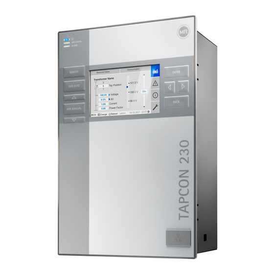
4 Product description 4.5 Design 4.5.1 Display, operating elements and front interface Figure 3: Voltage regulator 1 1 REMOTE key Activate REMOTE mode 2 AUTO key Activate AUTO mode 2 3 RAISE key Send a control command to the motor- drive unit to increase the voltage. 4 MANUAL key Activate MANUAL mode 2... -
Page 23: Leds
4 Product description 4.5.2 LEDs AVR STATUS EVENT Figure 4: LEDs 1 Power supply LED Blue Illuminates when the device is sup- plied with power. 2 AVR STATUS LED Illuminates when the device is in the error state. Yellow Illuminates when the device starts or has been paused;... -
Page 24: Connections And Fuses
4 Product description 4.5.3 Connections and fuses The connections are located on the rear of the device. You will find more in- formation on the connections in the Technical data [►Section 13, Page 114] section. Figure 5: Rear 1 F2 Internal fuse for the 2 X9 Power supply power supply... -
Page 25: Nameplate
4 Product description Connections and terminals Figure 6: Connections/terminals 1 COM-X6 CAN bus/SCADA 2 COM-X5 Interface for patch cable for interface RS485/re- SCADA via fiber-optic cable sistor contact series 3 COM-X4 Fiber-optic cable 4 COM-X3 SCADA interface RS232 (SFP cage for the SFP module) 5 COM-X2 Interface for visual- 6 COM-X1... -
Page 26: Safety Markings
4 Product description 4.5.5 Safety markings Warning of a danger point. Read the information given in the product oper- ating instructions. 4.5.6 Connection diagram and grounding screw Figure 8: Connection diagram/grounding screw 1 Grounding screw 2 Connection diagram ® TAPCON 230 Basic 7817441/03 EN Maschinenfabrik Reinhausen GmbH 2021... -
Page 27: Visualization
4 Product description 4.5.7 Visualization 4.5.7.1 Main screen Home Measured values Communication Transformer name Home 101.5 V Position Events 20 s 100.4 V Voltage 100.0 V 0.3% Information Current 40 mA 98.5 V Power factor Change Reboot admin 2020-04-15 10:08 Settings Figure 9: Home 1 Secondary navigation or naviga- 2 Primary navigation tion path 3 Status bar... - Page 28 4 Product description Measured values/display Transformer name Position Measured values Communication Voltage 100.4 V Transformer name Home 101.5 V Position 0.3% Events Current 40 mA 20 s 100.4 V Voltage 100.0 V 0.3% Power factor Information Current 40 mA 98.5 V Power factor Change Reboot admin 2020-04-15 10:08 Settings Figure 10: Measured values 1 Transformer name (can be edited)
- Page 29 4 Product description 4.5.7.2 Operating concept You can operate the device using the controls on the front panel or using the web-based Intuitive Control Interface visualization on a PC. The scope of function and structure of both options is virtually identical. User rights and user roles The device is equipped with a rights system and a roles system.
- Page 30 4 Product description 5. Select Time. In these operating instructions, the path for navigating to a parameter is al- ways shown in an abridged form: Go to Settings > Parameters > System > Time synchronization. Setting parameters There are various ways to configure the settings, depending on the parame- ter.
- Page 31 4 Product description Entering text 1. Use to select the text box and press ð If operating via the front panel, the keyboard appears. Figure 13: Entering text 2. Enter the desired text and confirm with 3. Press the Accept button to save the modified parameter. Parameter search You can use the quick search function in the parameter menu to search for a parameter.
- Page 32 4 Product description Expert mode The device has an expert mode for entering the parameters. You can enter the parameters directly on the overview screen of the respective menu in this mode. Figure 15: Expert mode To activate the expert mode, proceed as follows: 1.
-
Page 33: Packaging, Transport And Storage
5 Packaging, transport and storage 5 Packaging, transport and storage 5.1 Suitability, structure and production The goods are packaged in a sturdy cardboard box. This ensures that the shipment is secure when in the intended transportation position and that none of its parts touch the loading surface of the means of transport or touch the ground after unloading. -
Page 34: Storage Of Shipments
5 Packaging, transport and storage Visible damage If external transport damage is detected on receipt of the shipment, proceed as follows: ▪ Immediately record the transport damage found in the shipping docu- ments and have this countersigned by the carrier. ▪... -
Page 35: Mounting
6 Mounting 6 Mounting DANGER Electric shock! Risk of fatal injury due to electrical voltage. Always observe the following safety regulations when working in or on electrical equipment. ► Disconnect the equipment. ► Lock the equipment to prevent an unintentional restart. ►... -
Page 36: Minimum Distances
6 Mounting 6.2 Minimum distances NOTICE Damage to the device! Insufficient circulation of ambient air can result in damage to the device due to overheating. ► Keep the ventilation slots clear. ► Ensure sufficient distance to neighboring components. ► Only mount device in horizontal position (ventilation slots are at the top and bottom). - Page 37 6 Mounting Dimensions for the control panel cutout B: 202 mm (7.95 in) Figure 17: Dimensions for the cutout 1. Cut out the section for the control panel. Figure 18: Cutting out the section for the control panel 2. Slide the device into the cutout from the front and insert tension clamps. Figure 19: Inserting the device into the cutout ®...
-
Page 38: Wall Mounting With Housing (Optional)
6 Mounting 3. Secure the device using the tension clamps. Figure 20: Securing device ð The device is mounted and can be wired up. 6.3.2 Wall mounting with housing (optional) For wall mounting, the device is fixed to the wall in a housing. The housing is an optional accessory. - Page 39 6 Mounting ► Fix the device on the wall from behind using 4 screws (M5) Figure 22: Wall mounting ð The device is mounted and can be wired up Proceed with wiring as shown in the connection diagram and as described in the Connecting device section.
-
Page 40: Connecting Device
6 Mounting 6.4 Connecting device WARNING Electric shock! Connection errors can lead to death, injury or property damage. ► Ground the device with a protective conductor using the grounding screw on the housing. ► Note the phase difference of the secondary terminals for the current transformer and voltage transformer. -
Page 41: Electromagnetic Compatibility
6 Mounting Excessive line capacitance can prevent the relay contacts from interrupting the contact current. In control circuits operated with alternating current, take into account the effect of the line capacitance of long control cables on the function of the relay contacts. If you want to route Ethernet connections from a control cabinet or building, we recommend using fiber-optic cables (in accordance with the IEC 61850-90-4 recommendation). - Page 42 6 Mounting ▪ Separate system parts must be joined by a potential equalization. ▪ The device and its wiring must be at least 10 m away from circuit-break- ers, load disconnectors and busbars. 6.4.2.2 Wiring requirement of operating site Note the following when wiring the operating site: ▪...
- Page 43 6 Mounting Figure 24: Recommended connection of the shielding 1 Connection of the shielding via a 2 Full-surface connection of the single conductor shielding 6.4.2.3 Wiring requirement in control cabinet Note the following when wiring in the control cabinet: ▪ The control cabinet where the device will be installed must be prepared in accordance with EMC requirements: –...
-
Page 44: Connecting Cables To The System Periphery
6 Mounting Figure 25: Ground strap connection 6.4.3 Connecting cables to the system periphery To obtain a better overview when connecting cables, only use as many leads as necessary. To connect cables to the system periphery, proceed as follows: ü Only use the specified cables for wiring. Note the cable recommendation [►Section 6.4.1, Page 40]. -
Page 45: Wiring Digital Inputs Di
6 Mounting 1. Voltage measurement: Feed the wires into the terminals UI:X7-4 (N con- ductor) and UI:X7-3 (L conductor) and fasten them using a screwdriver. Figure 26: UI:X7-4/3 2. Current measurement: Feed the wires into the terminals UI:X7-2 (l) and UI:X7-1 (k) and fasten them using a screwdriver. Figure 27: UI:X7-2/1 6.4.5 Wiring digital inputs DI If you use digital inputs, these have to be supplied with an auxiliary voltage... -
Page 46: Wiring Digital Outputs Do
6 Mounting Auxiliary power supply for digital inputs 1. Feed the wires into the terminals X8:2 and X8:1 of the X8 plug in accor- dance with the connection diagram [►Section 13.12, Page 124] and fas- ten them using a screwdriver. 2. - Page 47 6 Mounting Miniature circuit breaker You must fuse the power supply circuit with a miniature circuit breaker. The miniature circuit breaker must have the following properties: ▪ Rated current: 6...10 A ▪ Triggering characteristic: C, K or Z Conductor cross-section For the power supply circuit, use a conductor cross-section suitable for the miniature circuit breaker that you have selected, but at least 1.5 mm (AWG 15).
-
Page 48: Performing Tests
► Prior to commissioning, check the supply voltage and the measured volt- age. ► Connecting the device to mains. ð The display shows the MR logo and then the operating screen. ð The voltage display LED on the top left of the device's front panel lights ®... -
Page 49: Initial Steps
7 Initial steps 7 Initial steps NOTICE Damage to device and system periphery! An incorrectly connected device can cause damage to the device and sys- tem periphery. ► Check the entire configuration before commissioning. As soon as the device has powered up and the start screen is displayed, you will be asked to make the following settings. - Page 50 7 Initial steps 3. Connect the PC and the device via the front interface using an Ethernet cable (RJ45 plug). Figure 30: Establishing a connection via the front interface 4. Enter the visualization's IP address http://192.168.165.1, or if SSL encryption is active, enter https://192.168.165.1 in the browser on the PC.
- Page 51 Download the operating instructions from the device to start device parame- terization. ► Select in the status line. ð The operating instructions will be downloaded. The document is also available for download in the MR Customer Portal and on our website www.reinhausen.com. ® Maschinenfabrik Reinhausen GmbH 2021 7817441/03 EN TAPCON 230 Basic...
-
Page 52: Commissioning
8 Commissioning 8 Commissioning NOTICE Damage to device and system periphery! An incorrectly connected device can cause damage to the device and sys- tem periphery. ► Check the entire configuration before commissioning. 8.1 Commissioning wizard If you want the device to help when setting the relevant parameters, you can use the commissioning wizard. -
Page 53: Checking Measured Values And Status Of Digital Inputs And Outputs
8 Commissioning When in delivery status, you can log in as the administrator as follows: ▪ User name: admin ▪ Password: admin During the function test, you must set the most important parameters. Details on the parameters listed can be found in the Operation [►Section 9, Page 55] chapter. - Page 54 8 Commissioning 14. Press to select auto mode. ð If the actual voltage is outside the bandwidth, the device returns the on-load tap-changer to the original operating position after 20 sec- onds. 15. Press to select manual mode. 16. Set the delay time T2 to 10 seconds and activate it [►Page 94]. 17.
-
Page 55: Operation
9 Operation 9 Operation This chapter describes all the functions and setting options for the device. 9.1 System 9.1.1 General You can set general parameters in this menu item. 9.1.1.1 Setting general device functions You can set general device functions with the following parameters. 1. - Page 56 9 Operation 4. Press the Accept button to save the modified parameter. Auto logout You can use this parameter to activate th automatic logout function. Time until auto logout You can use this parameter to set the time period of inactivity after which a user is automatically logged out.
-
Page 57: Configuring The Network
9 Operation 9.1.2 Configuring the network You can use this menu item to configure the necessary network interface. 1. Go to Settings > Parameters > System > Network settings. 2. Select the desired parameter. 3. Set the parameter. 4. Press the Accept button to save the modified parameter. IP address You can use this parameter to assign an IP address to the device. -
Page 58: Setting The Device Time
9 Operation TLS version You can use this parameter to set the accepted TLS versions. If you would like to establish an encrypted connection to the visualization, you must use an accepted TLS version. You can select the following options: Option Accepted TLS versions >= 1.0... -
Page 59: Setting The Screensaver
9 Operation Time zone To adjust the device time to your local time, you can use the time shift pa- rameter to set the time shift to UTC. Example: Region Time shift to UTC Mumbai, India UTC +5:30 h Beijing, China UTC +8:00 h Brasilia, Brazil UTC -3:00 h... -
Page 60: Configuring Syslog
9 Operation Dimming When you activate this function, the device reduces the brightness of the display when the adjustable waiting time has expired if no key is pressed. The device then switches back to full brightness when you subsequently press any key. If the screensaver and brightness dimming are activated, you have to press any key twice in order to reactivate the display at full brightness. -
Page 61: Linking Signals And Events
9 Operation If you use the standard RFC 5245 (TLS), you have to import the root certifi- cate and the client certificate with the corresponding key to the syslog server. For more information, refer to the section titled Importing data. Syslog server You can use this parameter to set the IP address of the syslog server. - Page 62 9 Operation The digital inputs available are each permanently linked to a General pur- pose input event message for this purpose. Input/command Event message Digital input 1 General purpose input 1 Digital input 2 General purpose input 2 Table 17: Links between digital inputs and event messages You can link the event messages with device functions and digital outputs.
-
Page 63: Configuring Digital Inputs And Outputs
9 Operation Activate desired value 3 If the assigned event is active, the device activates the desired value 3. 9.1.6.2 Linking digital outputs You can link each event with a digital output. The device provides 5 digital outputs (GPO) for this purpose. When you link a digital output to an event, the device issues a signal to this output if the event occurs. -
Page 64: Event Management
9 Operation The following information is displayed in tabular form for configuring the digi- tal inputs and outputs. Grayed-out elements cannot be changed. Property Options Function Function of the digital input (I: ...) or the digital output (O: ...). You can adjust the designation. - Page 65 9 Operation 9.1.8.1 Displaying and acknowledging events Displaying events ► Go to Events. ð A list of currently pending events appears. Acknowledging events Acknowledgeable events must be acknowledged in the event overview so that they are no longer displayed. All other events are automatically removed once the cause has been fixed (e.g.
-
Page 66: User Administration
9 Operation Events Event Time Home 18.03.2020 Limit value P>> 04:35:17/576 17.03.2020 Limit value P> 10:56:59/669 Events 16.03.2020 Limit value Q<< 08:22:11/125 12.03.2020 Limit value Q< 01:33:22/845 Information 10.02.2020 Ambient conditions ... 14:21:49/602 1 / 100+ Filter Recorder Export CHANGE REBOOT admin 06.04.2020 13:08... - Page 67 9 Operation 9.1.9.1 Activating/deactivating service user access The device is equipped with user access for the Maschinenfabrik Rein- hausen GmbH Technical Service department. This access is for error diag- nostics and troubleshooting in the event of device faults. You can use this parameter to activate or deactivate service user access. To safeguard IT security, only activate service user access for a limited time pe- riod for remedying faults.
- Page 68 9 Operation Upon delivery, the following roles are provided: Role Description Data display User who can only view data of relevance to operation. ▪ Display all parameters ▪ Display all events Diagnostics User who can view data and log data of relevance to oper- ation.
- Page 69 9 Operation 9.1.9.3 Changing password All users can change their passwords provided that the user account is not set up as a group account. You can only change a group account's pass- word if you are logged in as the administrator. Note that the password must satisfy the following requirements: ▪...
-
Page 70: Hardware
9 Operation 4. Select the role you want. 5. If necessary, activate the Group account, Active or Auto login options. 6. Press the Accept button to save the user. Editing users 1. Go to Settings > Administration > User. 2. Select the desired user in the list. 3. - Page 71 9 Operation Option Description System image Complete image of the system (software and configuration). If you are using the option "with history", all of the event memory entries are also exported. System configu- System configuration ration Event log All event memory entries. Parameter list Parameter list with descriptive text and values (min, max, cur- rent).
- Page 72 9 Operation 9.1.12.2 Importing data You can import the following data: Option Description System image Complete image of the system (software and configura- tion), with or without history. Settings All device settings: ▪ Parameter settings ▪ Event settings ▪ Administrative settings (users, access rights) The settings can also be imported from another device.
-
Page 73: Power Grid
9 Operation 9.2 Power grid 9.2.1 Transformer data The transformation ratios and measuring set-up for the voltage and current transformers used in the system can be set with the following parameters. The device uses this information to calculate the corresponding measured values on the primary side of the current transformer (and therefore the transformer) from the recorded measured values. - Page 74 9 Operation Voltage-transformer circuit You can use this parameter to set your voltage transformer's circuit. You can select the following options: Option Description 1 Ph phase voltage Measurement in 1-phase grid between the conductor and neutral conductor. 3 Ph differential voltage Measurement in 3-phase grid between 2 conductors 3 Ph phase voltage...
- Page 75 9 Operation 9.2.1.2.1 1-phase measurement Circuit 1-A Figure 32: Circuit 1-A ▪ The voltage transformer VT is connected to the phase conductor and the neutral conductor. ▪ The current transformer CT is looped into the phase conductor. ▪ The voltage U and current I are in phase.
- Page 76 9 Operation ▪ The voltage U and current I are in phase. ▪ The voltage drop on a phase conductor is determined by the current I If you use this circuit, set the device as follows: Parameter Option Voltage-transformer circuit 3 Ph phase voltage Current-transformer circuit 3 Ph phase current...
- Page 77 9 Operation Circuit 1-D Figure 35: Circuit 1-D ▪ The voltage transformer VT is connected to the phase conductors L1 and ▪ The current transformer CT is looped into the phase conductor L3. ▪ The current I is ahead of voltage U by 90°.
-
Page 78: Voltage Monitoring
9 Operation ▪ The current I is ahead of voltage U by 30°. This corresponds to a phase shift of -30°. ▪ The voltage drop on a phase conductor is determined by the current I If you use this circuit, set the device as follows: Parameter Option Voltage-transformer circuit... - Page 79 9 Operation ▪ Overvoltage U>: Upper limit 1 ▪ Overvoltage U>>: Upper limit 2 If the measured value is higher than the upper limit (> or >>) or lower than the lower limit (< or <<), the device transmits an event message. U>>...
-
Page 80: Current Monitoring
9 Operation Reaction You can use this parameter to set the behavior of the device if the measured value is higher than the upper limit (> or >>) or lower than the lower limit (< or <<). You can select the following options: Setting Behavior No reaction. - Page 81 9 Operation If the measured value is higher than the upper limit (> or >>) or lower than the lower limit (< or <<), the device transmits an event message. I>> I> I< I<< Figure 39: Example of current monitoring with the limit value I> being exceeded I>>...
-
Page 82: Power Monitoring
9 Operation Reaction You can use this parameter to set the behavior of the device if the measured value is higher than the upper limit (> or >>) or lower than the lower limit (< or <<). You can select the following options: Setting Behavior No reaction. - Page 83 9 Operation Delay time You can use this parameter to set the delay time in order to delay the issuing of the event message. Reaction You can use this parameter to set the behavior of the device if the measured value is higher than the upper limit (>...
-
Page 84: Power Flow Monitoring
9 Operation 9.2.5 Power flow monitoring A reversal of power flow occurs if the active power is negative. You can set the following parameters for this: ▪ Hysteresis ▪ Delay time ▪ Behavior 1. Go to Settings > Parameters > Grid > Power flow monitoring. 2. -
Page 85: Tapcon® 2Xx Retrofit
9 Operation Setting Behavior Auto/manual blocking ▪ The Reversal of power flow event is issued. ▪ If Z compensation is activated, this function is deacti- vated. ▪ Automatic regulation is blocked. ▪ You cannot perform tap-change operations in manual mode. Target tap position ▪... - Page 86 9 Operation 1. Go to Settings > Parameters > Grid > TAPCON® 2xx retrofit. 2. Select the desired parameter. 3. Set the desired parameter. 4. Press the Accept button to save the modified parameter. TAPCON® 2xx retrofit You can use this parameter to activate or deactivate the Retrofit TAPCON® 2xx function.
-
Page 87: On-Load Tap-Changer Regulator
9 Operation 9.3 On-load tap-changer regulator 9.3.1 Voltage regulation All of the parameters required for the control function are described in this section. 1. Go to Settings > Parameters > On-load tap-changer regulator > Volt- age regulation. 2. Select the desired parameter. 3. - Page 88 9 Operation Selecting a desired value You can use this parameter to select the desired value used for control. You can choose between desired value 1, desired value 2 and desired value 3. ü Type of remote desired value setting [►Page 87] selected. 1.
- Page 89 9 Operation Figure 41: Active power-dependent adjustment of desired voltage value Desired value Minimum desired value Measured active power Maximum desired value meas Active power at minimum de- Set desired value when mea- sired value sured active power = 0 Active power at maximum de- sired value Response to active power P being exceeded...
- Page 90 9 Operation Linear dependency with negative active power: If the measured active power P ≤ P ≤ 0, the desired value is calculated meas using the following equation: × P meas 0 - P Linear dependency with positive active power: If the measured active power 0 ≤ P ≤ P , the desired value is calculated meas...
- Page 91 9 Operation TDSC U0 You can use this parameter to set the desired value which is to be used when the measured active power is 0. 1. Go to Settings > Parameters > Control > TDSC U0. 2. Enter desired value at active power 0. 3.
- Page 92 9 Operation The following transformer values are used to determine the minimum band- width: Nominal voltage U = 11000 V Step voltage in tap position 4 U = 11275 V Step4 Step voltage in tap position 5 U = 11000 V Step5 Delay time T1 Delay time T1 delays the issuing of a tap-change command for a defined pe- riod.
- Page 93 9 Operation change command is issued after expiration of the set delay time T1. The on-load tap-changer carries out a tap-change in a raise or lower direction to return to the tolerance bandwidth. Figure 42: Behavior of the control function with delay time T1 1 Upper limit of bandwidth 4 Set delay time T1 2 Desired value...
- Page 94 9 Operation the device responds faster to large voltage changes in the grid. Regulation accuracy improves as a result but the frequency of tap-changes increases too. Figure 43: Diagram for integral time response ΔU/B Control deviation "ΔU" as % of desired value in relation to the set band- width "B"...
-
Page 95: Line Drop Compensation
9 Operation starts to count down. Once delay time T2 is complete, a control impulse is again issued to the motor-drive unit for the tap change to return to the tol- erance bandwidth. Figure 44: Behavior of the regulation function with delay times T1 and T2 1 Upper limit of bandwidth 4 Set delay times T1 and T2. - Page 96 9 Operation 9.3.2.1 R&X compensation R&X compensation can compensate for voltage losses on the lines and therefore ensure correct voltage at the load. This requires precise line data. After you have entered all of the line data, the device automatically calcu- lates the ohmic and inductive voltage drop and takes this into account for au- tomatic voltage regulation.
- Page 97 9 Operation Ohmic resistance load You can use this parameter to set the ohmic resistance load. Inductive resistance load You can use this parameter to set the inductive resistance load. Length of line You can use this parameter to set the length of line. 9.3.2.2 Z compensation To keep the voltage constant for the consumer, you can use Z compensation to activate a current-dependent voltage increase.
-
Page 98: U Bandwidth Monitoring
9 Operation 1. Go to Settings > Parameters > On-load tap-changer regulator > Com- pensation. 2. Select the desired parameter. 3. Set the desired parameter. 4. Press the Accept button to save the modified parameter. Voltage increase You can use this parameter to set the current-dependent voltage increase ∆U. - Page 99 9 Operation Function monitoring You can use this parameter to activate function monitoring. You can select the following options: Setting Behavior Function monitoring is deactivated. Only Auto Function monitoring is only active in AVR AUTO oper- ating mode. Auto and Manual Function monitoring is active in AVR AUTO and AVR MANUAL operating modes Table 38: Activate function monitoring...
-
Page 100: On-Load Tap-Changer
9 Operation 9.4 On-load tap-changer Operations counter The device's operations counter is automatically increased with every initi- ated tap-change operation. You can use this parameter to set the number of tap-change operations, such as for a comparison with the operations counter of the motor-drive unit. -
Page 101: Motor-Drive Unit And Control Cabinet
9 Operation 9.5 Motor-drive unit and control cabinet 9.5.1 Control of the motor-drive unit 9.5.1.1 Setting the switching pulse for controlling the motor-drive unit You can use the parameters Switching pulse type, Switching pulse time and Switching pulse pause to adapt the device switching pulse to the require- ments of the motor-drive unit controller. - Page 102 9 Operation Figure 48: Switching pulse time and switching pulse pause 1 Switching pulse time 2 Switching pulse pause Switching pulse time You can use this parameter to set the maximum duration of the switching pulse. The switching pulse resets after the switching pulse time has elapsed or if the device receives the Motor running signal beforehand or the tap posi- tion is changed.
- Page 103 9 Operation 3. Set the parameter. 4. Press the Accept button to save the modified parameter. Motor runtime You can use this parameter to set the motor runtime. Motor runtime monitoring You can use this parameter to activate or deactivate motor runtime monitor- ing.
- Page 104 9 Operation Switching direction monitoring is not active if you control the motor-drive unit with a continuous pulse [►Section 9.5.1.1, Page 101]. Also refer to 2 Setting the switching pulse for controlling the motor-drive unit [► 101] ® TAPCON 230 Basic 7817441/03 EN Maschinenfabrik Reinhausen GmbH 2021...
-
Page 105: Maintenance And Care
6. Select the desired device in the list. 7. Select the device in the Firmware tab and select the Create firmware button in the MR Versions entry for the desired version. If the firmware cannot be generated automatically, you will see the Request button, which you can use to send an request to Maschinenfabrik Reinhausen GmbH. -
Page 106: Establishing Connection To Visualization
10 Maintenance and care 10. Calculate the hash value of the downloaded zip file on your PC and com- pare it with the hash value displayed in the customer portal. If both val- ues are identical, the file was downloaded correctly. Depending on your operating system, you can calculate the hash value of the file in different ways. -
Page 107: Updating Application Software
10 Maintenance and care 3. Connect the PC and the device via the front interface using an Ethernet cable (RJ45 plug). Figure 50: Establishing a connection via the front interface 4. Enter the visualization's IP address http://192.168.165.1, or if SSL encryption is active, enter https://192.168.165.1 in the browser on the PC. - Page 108 10 Maintenance and care To load the application software, proceed as follows: 1. Press the LOGIN button and log in as a user with a parameter configura- tor or administrator user role. 2. Go to Information > Software and take note of the application software version.
-
Page 109: Fault Elimination
11 Fault elimination 11 Fault elimination This chapter describes how to rectify simple operating faults. 11.1 General faults Characteristics/details Cause Remedy No function No power supply. Check the power supply. ▪ Power supply LED does not Fuse tripped. Contact Maschinenfabrik Reinhausen GmbH. light up No function Configuration error... -
Page 110: Unwanted On-Load Tap-Change Operation
11 Fault elimination 11.3 Unwanted on-load tap-change operation Characteristics/detail Cause Remedy Compensation activated Setting: Check parameters. ▪ R-X compensation Correct if necessary. ▪ Z compensation Table 42: Unexplained tap change 11.4 Human-machine interface Characteristics/details Cause Remedy Display Power supply interrupted. Check the power supply. ▪... -
Page 111: Tap Position Capture Incorrect
11 Fault elimination Characteristics/details Cause Remedy Measured current Line to the current transformer in- Check wiring. terrupted. ▪ No measured value Short-circuiting jumper in current Remove the short-circuiting jumper. transformer is not removed. Measured current Current transformer not correctly Correct parameterization. parameterized. - Page 112 11 Fault elimination Please provide answers to the following questions: ▪ Has the software been updated? ▪ Has there previously been a problem with this device? ▪ Have you previously contacted Maschinenfabrik Reinhausen about this is- sue? If yes, then who was the contact? ®...
-
Page 113: Disposal
12 Disposal 12 Disposal Observe the national requirements applicable in the country of use. ® Maschinenfabrik Reinhausen GmbH 2021 7817441/03 EN TAPCON 230 Basic... -
Page 114: Technical Data
13 Technical data 13 Technical data 13.1 Display elements Display 5″ TFT colour display LEDs 3 LEDs for operation display and messages ▪ POWER, AVR STATUS, ALARM ▪ RAISE, LOWER, AUTO, MANUAL, REMOTE 13.2 Materials Front Aluminum, plastic Tray/rear Stainless steel 13.3 Dimensions W x H x D 218 mm x 324 mm x 130 mm (8.58 in x 12.76 in x... -
Page 115: Voltage Measurement And Current Measurement
13 Technical data Auxiliary power supply AUX DC DI 110 V DC for digital inputs The auxiliary power supply is used exclusively for the acquisition of up to 16 floating contacts. Output voltage : 110 V DC ± 2% (short-circuit proof) Max. output power 5 W Overvoltage category OC III... -
Page 116: Central Processing Unit
13 Technical data Overload capability continu- 12.5 A Overload capacity short-term 500 A / 1 s Surge test voltage 5 kV, 1.2 µs / 50 µs (IEC 60255-27) Interface Description VT (U : 100/230/400 V AC) Table 50: Connection UI:X7 13.6 Central processing unit Processor ARM Cortex A9 processor 800 MHz 512 MB NVRAM (SRAM with battery 256 kB backup) Application memory... - Page 117 13 Technical data Interfaces Interface Description ER_NO ER_NC ER_COM WD_NO WD_NC WD_COM Table 51: Plug terminal CPU:X1 Interface X2, X3 Description RXD- RXD+ TXD- TXD+ Table 52: Ethernet interface CPU:X2/X3 Interface X4 Description TXD+/RXD+ TXD-/RXD- Table 53: Serial interface RS485 CPU:X4 ® Maschinenfabrik Reinhausen GmbH 2021 7817441/03 EN TAPCON 230 Basic...
-
Page 118: Digital Inputs
13 Technical data Interface X5 Description DTR (O) DCD (I) RXD (I) TXD (O) VCC/OUT 5 V/12 V RTS (O) CTS (I) Table 54: Serial interface RS232 CPU:X5 13.7 Digital inputs DI 16-110V Inputs (plug-based electrical 2 x 8 isolation) Nominal voltage 110 VDC Max. -
Page 119: Digital Outputs
13 Technical data Interface Description Common reference (common) Common reference (common) Input 17 Input 16 Input 15 Input 14 Input 13 Input 12 Input 11 Input 10 Table 57: Connector X2 (group 1) 13.8 Digital outputs DO 8 Outputs (plug-based electrical isola- 8 relays tion) 4 groups per module Switching voltage... - Page 120 13 Technical data Ohmic load Figure 51: Contact load capacity of digital outputs with resistive load Electric shock! CAUTION The outputs of the DO assembly have plug-based electrical isolation. A mix- ture of voltage ranges (e.g. extra low voltage and low voltage) or various phases within a plug can lower the protection against electric shock.
-
Page 121: Communication Interfaces
13 Technical data Interface Description Common reference (common) output 5 Common reference (common) output 4 Output 5 Output 4 Table 61: Connector X3 (group 2) Interface Description Common reference (common) output 7 Common reference (common) output 6 Output 7 Output 6 Table 62: Connector X4 (group 3) 13.9 Communication interfaces Description Assembly for converting interfaces and media... -
Page 122: Ambient Conditions
13 Technical data Interface Description TxD+ TxD- RxD+ RxD- Table 63: COM X2, COM X5 (RJ45) 13.10 Ambient conditions Operating temperature -25...+70°C Storage temperature -30...+85°C (with battery) Relative humidity 5...95%, non-condensing Contamination level Protection class Degree of protection Front: IP54 Rear: IP20 With optional housing: IP66 Maximum installation alti- 3,000 m above mean sea level... -
Page 123: Standards And Directives
13 Technical data 13.11 Standards and directives Electromagnetic compatibility IEC 61000-6-2, IEC 61000-6-4, IEC 61000-6-5 EN 60255-26 KN 61000-6-2, KN 61000-6-4 FCC 47 CFR Part 15 B ICES-003 Electrical safety IEC 61010-1 IEC 61010-2-201 IEC 61010-2-030 EN 61010-1 UL 61010-1 CAN/CSA-C22.2 No. 61010-1 Measurement relays and protective de- IEC 60255-1:2009 Section 6.10.1, 6.10.2 vices and 6.10.4 IEC 60255-27:2013 Section 10.6.4.2,... -
Page 124: Connection Diagrams
13 Technical data 13.12 Connection diagrams Also refer to 2 TAPCON® 230 Basic [► 125] ® TAPCON 230 Basic 7817441/03 EN Maschinenfabrik Reinhausen GmbH 2021... -
Page 125: Tapcon® 230 Basic
TAPCON® 230 - BASIC CENTRAL PROCESSING UNIT POWER SUPPLY DIGITAL OUTPUTS DO 8-1 DIGITAL INPUTS DI 16-110V AC/DC N (L-) L1 (L+) 110V DC X7,X1 connection 29.09.21 LAINER LANGUAGE: PROJECT: DATE 22.01.2021 DEL BCD 16.09.21 BECK EXEC. BECK TAPCON® 230 BASIC BCD signals 28.06.21 M Kahn... - Page 126 CUSTOMER VISU / SERVICE RJ45 RJ45 RJ45 RJ45 X7,X1 connection 29.09.21 LAINER LANGUAGE: PROJECT: DATE 22.01.2021 DEL BCD 16.09.21 BECK EXEC. BECK TAPCON® 230 BASIC BCD signals 28.06.21 M Kahn VERIFIED SHEET 7826272_03 MODIFICATION DATE NAME STANDARD ORIGIN. REPL. REPL.BY...
-
Page 127: Glossary
Glossary Glossary Electromagnetic compatibility Abbreviation for fiber-optic cable SNTP General Purpose Input NTP (Network Time Protocol) is a standard for synchronizing clocks in computer systems using packet-based communication networks. SNTP (Simple Network Time Protocol) is the simplified General Purpose Output version of NTP. - Page 130 Maschinenfabrik Reinhausen GmbH Falkensteinstrasse 8 93059 Regensburg +49 (0)941 4090-0 sales@reinhausen.com www.reinhausen.com ® 7817441/03 EN - TAPCON 230 Basic - - 11/21 - Maschinenfabrik Reinhausen GmbH 2021 THE POWER BEHIND POWER.
Need help?
Do you have a question about the TAPCON 230 Basic and is the answer not in the manual?
Questions and answers