Table of Contents
Advertisement
Advertisement
Table of Contents

Related Manuals for MR TAPCON 240


Summary of Contents for MR TAPCON 240
- Page 1 Voltage regulator TAPCON® 240 Quick reference guide 230/05...
- Page 2 © All rights reserved by Maschinenfabrik Reinhausen Copying and distribution of this document and utilization and communication of its contents are strictly prohibited unless expressly authorized. Offenders will be held liable for the payment of damages. All rights reserved in the event of the grant of a patent, utility model or ornamental design registration.
-
Page 3: Table Of Contents
Table of Contents Table of Contents Introduction .................. 5 1.1 Manufacturer ..................... 5 1.2 Completeness ................... 5 1.3 Supporting documents ................6 1.4 Safekeeping ....................6 Safety .................... 7 Product description ..............9 3.1 Operation and indicator elements ............ - Page 4 4.6 Configuration ..................31 4.6.1 Transformer data ....................31 4.6.2 General ....................... 40 4.7 Displaying the info screen ..............42 MR worldwide ................45 TAPCON® 240 230/05 EN © Maschinenfabrik Reinhausen 2010...
-
Page 5: Introduction
1 Introduction Introduction This technical file contains information for quick start-up of the voltage regula- tor. It does not provide comprehensive operating instructions. This technical file is intended solely for specially trained and authorized per- sonnel. Manufacturer The product is manufactured by: Maschinenfabrik Reinhausen GmbH Falkensteinstrasse 8 93059 Regensburg... -
Page 6: Supporting Documents
1 Introduction Supporting documents The following documents apply to this product: Operating instructions Commissioning instructions Quick reference guide Connection diagrams All documents form part of the scope of delivery. In addition, generally applicable legal and other binding regulations of Euro- pean and national law and the regulations for accident prevention and envi- ronmental protection in force in the country of use must be complied with. -
Page 7: Safety
2 Safety Safety This technical file does not replace the operating instructions for the voltage regulator. The quick reference guide contains information that will provide a rapid introduction to operating the voltage regulator. For detailed operation and safety information please read carefully through the voltage regulator operating instructions. -
Page 9: Product Description
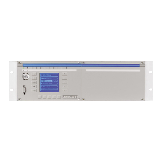
Product description Figure 1 Front view of voltage regulator 19-inch plug-in housing (in accordance with DIN 41494 Part 5) Operating panel with display and LEDs Assembly for optional add-ons (e.g. TAPCON 240 LV) © Maschinenfabrik Reinhausen 2010 230/05 EN TAPCON® 240... -
Page 10: Operation And Indicator Elements
3 Product description Operation and indicator elements The front of the voltage regulator is split into different areas for operating the device and displaying information. Below you can see an overview of the indi- vidual elements. Figure 2 Voltage regulator operating panel LEDs Keys for parameterization and configuration Serial interface COM1 (RS232) -
Page 11: Description Of The Display
3 Product description Description of the display Figure 3 Main screen Status line Measured voltage V actual Desired voltage V desired Other measured values (use to switch between them) Tap position (n-1, n, n+1) Bandwidth (upper and lower limit) Time bar for delay time T1 Highlighting for desired voltage Highlighting for measured voltage Remaining delay time T1... - Page 12 3 Product description In auto and manual mode the measured value display can be set using the keys. The following measured values can be displayed: Control deviation (dV:) Current (I:) Apparent power (Powr.:) Active power (P:) ...
-
Page 13: Description Of Key Functions
3 Product description Description of key functions Symbol Function RAISE In manual mode the motor-drive unit can be operated directly using the RAISE key. Using RAISE, the motor-drive unit changes the on-load tap- changer and therefore the step voltage. LOWER In manual mode the motor-drive unit can be operated directly using the LOWER key. -
Page 14: Description Of Leds
3 Product description Description of LEDs The voltage regulator has 10 LEDs above the display. These indicate various operating statuses or events. Figure 4 Description of LEDs Green Operating display Overcurrent blocking Undervoltage blocking Overvoltage blocking Green Parallel operation On Green NORMset On Yellow... -
Page 15: Functions And Settings
4 Functions and settings Functions and settings This chapter gives a short summary of all the functions and possible settings of the voltage regulator. For details, see the voltage regulator operating instructions. Key lock The voltage regulator is equipped with a key lock for protection against unin- tentional operation. -
Page 16: Setting The Language
4 Functions and settings Setting the language The required display language can be set or changed in any way. The follow- ing languages are available: English German French Spanish Italian Portuguese > Configuration > General. -
Page 17: Normset
4 Functions and settings NORMset Instead of parameterizing the voltage regulator manually, NORMset mode enables easy and user-friendly commissioning of the voltage regulator with a limited set of parameters. When this mode is selected, the factory settings re- quired for voltage regulation are adopted. If NORMset is activated, the bandwidth and delay time settings will be un- dertaken automatically by the voltage regulator. -
Page 18: Entering Normset Desired Value 1
4 Functions and settings 4.4.1 Entering NORMset desired value 1 Desired values set in kV apply to the primary voltage of the connected voltage transformer. Desired values set in kV apply to the secondary voltage of the connected voltage transformer. All transformer data (see "Transformer da- ta"... -
Page 19: Setting The Primary Voltage
4 Functions and settings 4.4.2 Setting the primary voltage In general, the regulator only indicates the secondary voltage in V if you have not set the primary voltage. The primary voltage is only displayed if parameter "Display V / kV" has been set to kV (see "Setting the voltage display kV/V"... - Page 20 4 Functions and settings To set the primary voltage, proceed as follows: > Normset > 2x <02> Primary voltage. 2. Press to highlight the decimal place. The decimal place is defined and the value can be changed. 3. Press to highlight a digit position. The digit position you want is highlighted and the value can be changed.
-
Page 21: Setting The Secondary Voltage
4 Functions and settings 4.4.3 Setting the secondary voltage The secondary voltage is displayed and entered in V. Setting range Step size Factory setting 57 V...125 V 0.1 V 100 V Table 5 Setting range for secondary voltage in V To set the secondary voltage, proceed as follows: >... -
Page 22: Parameters
4 Functions and settings Parameters This section describes all the functions, parameters and recommended setting ranges for voltage regulation using the voltage regulator. To make it easier for you to find specific parameters, the description refers to subgroups of individ- ual parameters with related functions. - Page 23 4 Functions and settings Setting range Step size Factory setting 49 V…140 V 0.1 V 100 V Table 6 Setting range for desired value 1 in V Setting range Step size Factory setting 0.1 kV...999.9 kV 1 kV 0.1 kV...99.9 kV 0.1 kV 0.1 kV...99.99 kV 0.01 kV...
-
Page 24: Bandwidth
4 Functions and settings 4.5.2 Bandwidth The bandwidth is the permitted deviation of the measured voltage from the se- lected desired value. If the measured voltage is inside the bandwidth, then no control commands are issued to the on-load tap-changer. If the measured voltage deviates from the specified bandwidth, a tap-change command occurs after the set delay time T1. - Page 25 4 Functions and settings Figure 6 Visual display of deviation from desired value Bandwidth (upper and lower limit) Time bar for delay time T1 Desired voltage value Measured voltage Remaining delay time T1 4.5.2.1 Determining bandwidth In order to be able to set the value correctly, the transformer's step voltage and nominal voltage must be known.
- Page 26 4 Functions and settings where: Step voltage of position n-1 Step voltage of position n Nominal voltage nominal The bandwidth must be selected in such a way that the output voltage of the transformer (V ) returns to within the specified tolerance range after actual the tap change .
- Page 27 4 Functions and settings 4.5.2.2 Setting the bandwidth Setting range Step size Factory setting 0.5 %...9 % 0.01 %...1 % Table 8 Setting range for bandwith The calculated bandwidth is entered as follows: > Parameter > Control para- meter > 3x <03>...
-
Page 28: Setting Delay Time T1
4 Functions and settings 4.5.3 Setting delay time T1 Time delay T1 delays the issuing of a tap-change command for a defined pe- riod. This function prevents unnecessary tap change operations if the toler- ance bandwidth is exited for a short time. Setting range Step size Factory setting... -
Page 29: Activate/Deactivate Delay Time T2
4 Functions and settings To set the control response T1, proceed as follows: > Parameter > Control para- meter > 5x <05> Control response T1. 2. Press to select "T1 linear" or to se- lect "T1 integral". 3. Press The control response T1 is set. 4.5.4 Activate/deactivate delay time T2 The delay time T2 only takes effect if more than one tap-change operation is... -
Page 30: Setting Delay Time T2
4 Functions and settings 4.5.5 Setting delay time T2 The following section describes how to set the delay time T2. Setting range Step size Factory setting 1 s...10 s 0.1 s 10 s Table 10 Setting range for delay time T2 In general, the delay time T2 should be greater than the pulse duration and the maximum ope-rating time of the motor-drive unit. -
Page 31: Configuration
4 Functions and settings Configuration This section describes how to carry out all the settings for configuring system- specific data. To make it easier for you to find specific parameters, the de- scription refers to subgroups of individual parameters with related functions. 4.6.1 Transformer data The transformation ratios and measuring set-up for the voltage and current... - Page 32 4 Functions and settings Setting range Step size Factory setting 0 kV... 9999 kV 1 kV 0 kV...999.9 kV 0.1 kV 100 kV 0 kV...99.99 kV 0.01 kV Table 11 Setting range for primary transformer voltage To set the primary transformer voltage, proceed as follows: >...
- Page 33 4 Functions and settings 4.6.1.2 Setting the secondary transformer voltage The secondary transformer voltage is displayed and entered in V. Setting range Step size Factory setting 100 V...110 V 0.1 V 100 V Table 12 Setting range for secondary transformer voltage To set the secondary transformer voltage, proceed as follows: >...
- Page 34 4 Functions and settings Setting the primary transformer current 4.6.1.3 In general the voltage regulator displays the percentage current of the chosen measurement input. As soon as the primary rated current (e.g. 50 A) is en- tered in the voltage regulator, the display in the Info menu switches over to "A"...
- Page 35 4 Functions and settings 4.6.1.4 Setting the current transformer connection The current transformer connection must be selected in order to obtain the correct display. If you set the current transformer connection to "Unknown" in the display, the percentage value is shown. However, if a connection is se- lected, the absolute value (in amps) is displayed.
- Page 36 4 Functions and settings 4.6.1.5 Setting the phase angle for the current/voltage transformer The normal measuring circuit values can be set as follows: System Setting Display Single-phase 0 1PH Three-phase 0 3PH Three-phase 90 3PH Three-phase 30 3PH Three-phase -30 3PH Table 14 Setting options for the measuring circuits Circuit a:...
- Page 37 4 Functions and settings Circuit a: Figure 8 Circuit a - phase angle to be set 0;3PH Voltage transformer VT is connected to U and N. Current transformer CT is looped in U. Voltage V and current I are in phase.
- Page 38 4 Functions and settings Circuit c: Figure 10 Circuit c - phase angle to be set 90;3PH Voltage transformer VT is connected to U and V. Current transformer CT is looped in W. Current I ahead of voltage V V by 90°.
- Page 39 4 Functions and settings Circuit e Figure 12 Circuit e - phase angle to be set -30;3PH Voltage transformer VT is connected to U and V. Current transformer CT is looped in U. Current I lags behind voltage V by -30°.
-
Page 40: General
4 Functions and settings 4.6.2 General This submenu enables general settings, which are also required for commis- sioning, to be made on the device. You can change the following general set- tings: 4.6.2.1 Setting the voltage display kV/V Switching the display from V to kV converts and displays the measurements and setting values in the device on the primary side of the voltage transfor- mer. - Page 41 4 Functions and settings 4.6.2.2 Setting current display unit In this display, you can set the unit for the limit values displayed for overcur- rent and undercurrent as a percentage ("%") or absolute value ("A"). It is only possible to change from % to A if all the transformer data have pre- viously been entered.
-
Page 42: Displaying The Info Screen
4 Functions and settings Displaying the info screen Information on the device can be viewed here. Figure 13 Info screen Type designation Software version Date of issue Size of EEPROM / ID number of module Flash memory RAM memory To display the info screen, proceed as follows: ►... - Page 43 4 Functions and settings By pressing , the following information is also displayed: <01> Measured values <02> LED test <03> Input/output status <04> UC1 card status <05> UC2 card status <06> Parameter <07> RTC ...
-
Page 45: Mr Worldwide
Fax. +7 495 980 89 67 E-mail: sales@au.reinhausen.com E-mail: mrr@reinhausen.ru Brazil Japan South Africa MR do Brasil Indústria Mecánica Ltda. MR Japan Corporation Reinhausen South Africa (Pty) Ltd. Av. Elias Yazbek, 465 German Industry Park No. 15, Third Street, Booysens Reserve... - Page 46 230/05 EN 12/10 Maschinenfabrik Reinhausen GmbH Phone: +49 941 4090 0 www.reinhausen.com Falkensteinstrasse 8 Fax: +49 941 4090 7001 93059 Regensburg Email: sales@reinhausen.com...
Need help?
Do you have a question about the TAPCON 240 and is the answer not in the manual?
Questions and answers