MR TAPCON 250 Operating Instructions Manual
Voltage regulator
Hide thumbs
Also See for TAPCON 250:
- Supplement manual (20 pages) ,
- Operating instructions manual (216 pages)
Table of Contents
Advertisement
Advertisement
Table of Contents

Related Manuals for MR TAPCON 250


Summary of Contents for MR TAPCON 250
- Page 1 Voltage Regulator TAPCON® 250 Operating Instructions 297/07 EN...
- Page 2 © All rights reserved by Maschinenfabrik Reinhausen Dissemination and reproduction of this document and use and disclosure of its content are strictly prohibited unless expressly permitted. Infringements will result in liability for compensation. All rights reserved in the event of the granting of patents, utility models or designs.
-
Page 3: Table Of Contents
Table of contents Table of contents Introduction......................... 8 Manufacturer............................8 Completeness............................8 Safekeeping............................8 Notation conventions........................... 8 1.4.1 Hazard communication system..........................8 1.4.2 Information system.............................. 10 1.4.3 Instruction system............................... 10 1.4.4 Typographic conventions............................ 11 Safety..........................12 Appropriate use..........................12 Fundamental Safety Instructions....................... 12 Personnel qualification........................ - Page 4 Table of contents Transportation, receipt and handling of shipments................29 Storage of shipments......................... 30 Mounting..........................31 Mounting device..........................31 Connecting device..........................32 5.2.1 Cable recommendation............................32 5.2.2 Electromagnetic compatibility..........................33 5.2.3 Information about laying fiber-optic cable......................36 5.2.4 Connecting cables to the system periphery......................37 5.2.5 Wiring device...............................
- Page 5 Table of contents 7.4.1 Setting desired value 1...4........................... 68 7.4.2 Analog setting of the desired value (optional)..................... 69 7.4.3 Bandwidth................................72 7.4.4 Setting voltage balance............................75 7.4.5 Setting delay time T1............................75 7.4.6 Setting control response T1..........................76 7.4.7 Setting delay time T2............................77 Limit values............................
- Page 6 Table of contents 7.11.3 Setting time difference of average value interval....................107 7.11.4 Setting event memory size..........................107 7.11.5 Time plotter............................... 110 7.12 Communication interface......................... 116 7.12.1 Selecting the communication protocol....................... 116 7.12.2 Selecting communication port........................... 117 7.12.3 Selecting communication baud rate........................117 7.12.4 Assigning network address..........................
- Page 7 Table of contents 7.14.14 Displaying upcoming messages........................134 7.14.15 Display of the consumption..........................135 Fault elimination......................136 No regulation in AUTO mode......................136 Unexplained tap change........................137 Man-machine interface........................137 Incorrect measured values......................137 Parallel operation faults........................138 Customized GPIs/GPOs........................139 General faults..........................
-
Page 8: Introduction
1 Introduction Introduction This technical file contains detailed descriptions on the safe and proper in- stallation, connection, commissioning and monitoring of the product. It also includes safety instructions and general information about the prod- uct. This technical file is intended solely for specially trained and authorized per- sonnel. - Page 9 1 Introduction 1.4.1.1 Warning relating to section Warnings relating to sections refer to entire chapters or sections, sub-sec- tions or several paragraphs within this technical file. Warnings relating to sections use the following format: Type of danger! WARNING Source of the danger and outcome. ►...
-
Page 10: Information System
1 Introduction Pictogram Meaning Warning of dangerous electrical voltage Warning of combustible substances Warning of danger of tipping Table 2: Pictograms used in warning notices 1.4.2 Information system Information is designed to simplify and improve understanding of particular procedures. In this technical file it is laid out as follows: Important information. -
Page 11: Typographic Conventions
1 Introduction Aim of action ü Requirements (optional). Step 1. ð Result of step (optional). Step 2. Result of step (optional). ð ð Result of action (optional). 1.4.4 Typographic conventions The following typographic conventions are used in this technical file: Typographic convention Purpose Example... -
Page 12: Safety
2 Safety Safety Appropriate use The TAPCON® keeps the output voltage of a transformer with an on-load tap-changer constant. The product is designed solely for use in stationary large-scale electrical energy systems and facilities. If used as intended, in compliance with the requirements and conditions specified in this technical file and observing the warning notices in this tech- nical file and attached to the product, the product does not pose risk of injury or damage to property or the environment. - Page 13 2 Safety Work area Untidy and poorly lit work areas can lead to accidents. ▪ Keep the work area clean and tidy. ▪ Make sure that the work area is well lit. ▪ Observe the applicable laws for accident prevention in the relevant country.
-
Page 14: Personnel Qualification
2 Safety Safety markings Warning signs and safety information plates are safety markings on the product. They are an important aspect of the safety concept. ▪ Observe all safety markings on the product. ▪ Make sure all safety markings on the product remain intact and legible. ▪... -
Page 15: Personal Protective Equipment
2 Safety ▪ Is specially trained for the working environment in which (s)he works. ▪ Must satisfy the requirements of the applicable statutory regulations for accident prevention. Electrically trained persons An electrically trained person receives instruction and guidance from an electrically skilled person in relation to the tasks undertaken and the poten- tial dangers in the event of inappropriate handling as well as the protective devices and safety measures. - Page 16 2 Safety Personal protective equipment to be worn at all times Protective clothing Close-fitting work clothing with a low tearing strength, with tight sleeves and with no pro- truding parts. It mainly serves to protect the wearer against being caught by moving ma- chine parts.
-
Page 17: Product Description
This chapter contains an overview of the design and function of the product. Scope of delivery The following items are included in the delivery: ▪ TAPCON® 250 ▪ CD MR-Suite (contains the TAPCON®-trol program) ▪ Technical files ▪ Serial cable RS232 ▪... -
Page 18: Operating Modes
3 Product description ▪ Display of all measured values such as voltage, current, active power, apparent power or reactive power, power factor (cos φ) ▪ Selection of 4 different desired values ▪ Desired value setting by means of analog signals (optional) ▪... - Page 19 3 Product description + LOCAL + RE- + LOCAL + RE- MOTE MOTE Automatic regulation Tap-change operation via operat- ing controls Tap-change operation via inputs Tap-change operation via SCADA Value adjustment via SCADA* Table 4: Overview of operating modes *) Optional when connecting TAPCON® to a control system (SCADA) Maschinenfabrik Reinhausen GmbH 2018 297/07 EN TAPCON®...
-
Page 20: Hardware
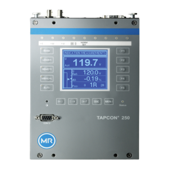
3 Product description Hardware The individual assemblies are mounted in optimized, EMC-protected hous- ings. The front plate contains the operating controls, the display and the LEDs. Figure 1: Front view TAPCON® 250 297/07 EN Maschinenfabrik Reinhausen GmbH 2018... -
Page 21: Name Plate
3 Product description 3.5.1 Name plate The nameplate can be found on the rear side of the device and contains the following information: Figure 2: Example appearance of the nameplate S/N Serial number (e.g. SKJVN140195) Art.: Article number in accordance with configuration (e.g. TC250-4-P- C1-03) Article number The article number is composed in accordance with your order and is con-... - Page 22 3 Product description Scheme Possible parameters SCADA (CI module) ▪ 0: No CI module ▪ C: CI module with RS232 and RS485 ▪ E: CI module with RS232, RS485 and RJ45 (Ethernet) ▪ M: CI module with RS232, RS485 and RJ45 (mo- dem) Optional fiber-optic cable (CI module) ▪...
-
Page 23: Operating Controls
3 Product description 3.5.2 Operating controls The device has 15 pushbuttons. The illustration below is an overview of all the device's operating controls. Figure 3: Operating controls RAISE key: In manual mode, send a control command to the mo- tor-drive unit to increase the voltage. LOWER key: In manual mode, send a control command to the mo- tor-drive unit to reduce the voltage. - Page 24 3 Product description MENU key: Select main menu. F1 to F5 function keys: Select functions displayed on the screen. TAPCON® 250 297/07 EN Maschinenfabrik Reinhausen GmbH 2018...
-
Page 25: Display Elements
3 Product description 3.5.3 Display elements The device has a graphics display and 15 LEDs, which indicate the various operating statuses or events. Figure 4: Display elements 1 Overcurrent blocking LED, red 9 LED 4, function can be freely assigned, green/yellow/red 2 Undervoltage blocking LED, 10 Graphics display 3 Overvoltage blocking LED, red... -
Page 26: Serial Interface
3 Product description 3.5.4 Serial interface The parameters for the device can be set using a PC. The COM 2 (RS232) serial interface on the front panel is provided for this purpose. You can use the connection cable supplied to establish a connection to your PC via the RS232 or USB port (using the optional USB adapter). - Page 27 3 Product description 3.5.5.2 CI module (optional) The optional CI module makes 4 additional communication interfaces availa- ble: ▪ RS232 ▪ RS485 ▪ Ethernet/modem ▪ Fiber-optic cable You can tether the device to a control system using these communication in- terfaces.
-
Page 28: Packaging, Transport And Storage
4 Packaging, transport and storage Packaging, transport and storage Packaging The products are sometimes supplied in a sealed packaging and sometimes in a dry state depending on requirements. A sealed packaging surrounds the packaged goods on all sides with plastic foil. -
Page 29: Transportation, Receipt And Handling Of Shipments
4 Packaging, transport and storage Protect Fragile Attach lifting Center of against mois- gear here mass ture Table 6: Shipping pictograms Transportation, receipt and handling of shipments In addition to oscillation stress, jolts must also be expected during transpor- tation. In order to prevent possible damage, avoid dropping, tipping, knock- ing over and colliding with the product. -
Page 30: Storage Of Shipments
4 Packaging, transport and storage Hidden damage When damages are not determined until unpacking after receipt of the ship- ment (hidden damage), proceed as follows: ▪ Make the party responsible for the damage liable as soon as possible by telephone and in writing, and prepare a damage report. ▪... -
Page 31: Mounting
5 Mounting Mounting This chapter describes how to correctly install and connect the device. Ob- serve the connection diagrams provided. Electric shock! DANGER Risk of fatal injury due to electrical voltage. Always observe the following safety regulations when working in or on electrical equipment. ►... -
Page 32: Connecting Device
5 Mounting Connecting device The following section describes how to establish the electrical connection to the device. Electric shock! WARNING Connection errors can lead to death, injury or property damage. ► Ground the device with a protective conductor using the grounding screw on the housing. -
Page 33: Electromagnetic Compatibility
5 Mounting Cable Terminal Cable type Conductor Max. length Max. permissible cross-section torque CAN bus Shielded AWG 18 (1.0 1.2 miles 4.5 lb in (0.5 Nm) 80 Ω/mile (50 mm²) (2000 m) Ω/km) Voltage measure- P2.1...P2.6 Unshielded AWG 12...24 4.5 lb in (0.5 Nm) ment, current (0.2..3.3 measurement... - Page 34 5 Mounting ▪ Maintain a distance of more than 100 mm between lines which cause in- terference and those which are susceptible to interference. Figure 7: Recommended wiring 1 Cable duct for lines causing in- 3 Cable duct for lines susceptible terference to interference 2 Line causing interference (e.g.
- Page 35 5 Mounting Figure 8: Recommended connection of the shielding 1 Connection of the shielding via 2 Full-surface connection of the a single conductor shielding 5.2.2.3 Wiring requirement in control cabinet Note the following when wiring the control cabinet: ▪ The control cabinet where the device will be installed must be prepared in accordance with EMC requirements: –...
-
Page 36: Information About Laying Fiber-Optic Cable
5 Mounting 5.2.2.4 Information about shielding the CAN bus In order for the CAN bus to operate faultlessly, you have to connect the shielding using one of the following variants. If you are not able to use any of the variants detailed below, we recommend using fiber-optic cables. Fiber- optic cables decouple the devices and are not sensitive to electromagnetic interference (surge and burst). -
Page 37: Connecting Cables To The System Periphery
5 Mounting ▪ Be aware of sharp edges because they can damage the fiber-optic ca- ble's coating during laying or can place mechanical loads on the coating later on. ▪ Provide a sufficient cable reserve near distributor cabinets. Lay the re- serve such that the fiber-optic cable is neither bent nor twisted when tightened. - Page 38 5 Mounting ► Wire the device according to the connection diagram. Figure 9: Connection terminals of the device TAPCON® 250 297/07 EN Maschinenfabrik Reinhausen GmbH 2018...
- Page 39 5 Mounting 5.2.5.1 Terminal P1: CAN bus Terminal P1 is for connecting the device to the CAN bus. You can use the CAN bus to operate several TAPCON® units in parallel. Figure 10: Connection diagram for parallel operation of several TAPCON® 250 units via CAN bus.
- Page 40 5 Mounting 5.2.5.2 Terminal P2: External connections Figure 11: Connection diagram for terminal P2 connections Note that the two input groups P2.26 (MANUAL/AUTO) and P2.27 (LOCAL/ REMOTE), and P2.28 (RAISE) and P2.29 (LOWER) have their own refer- ence potentials. In order to prevent any damage, the signal voltages of the two input groups must therefore refer to the same reference potential.
- Page 41 5 Mounting Connection P2.1, voltage input Input for voltage measurement and supplying the TAPCON® 250. Permissi- ble voltage range of 85...140 V AC. The power consumption of the TAP- CON® 250 is 6...12 VA (depending on the product version). The voltage is in reference to the neutral conductor (P2.3).
- Page 42 5 Mounting Connection P2.10, 12 V DC auxiliary voltage output Auxiliary voltage output (12 V DC) for wiring the general purpose inputs (GPI). Depending on the voltage at P2.1 and the connected load, the output voltage is 10...18 V DC and the maximum current is 100 mA. Note that the output is not internally protected.
- Page 43 5 Mounting Connection P2.25, common P2.26 and P2.27 This is the common connection for inputs P2.26 and P2.27. Connection P2.26, MANUAL/AUTO input This input is used for connecting an external MANUAL/AUTO switch. You can activate the voltage regulator's Auto operating mode with this switch. The Auto operating mode is active if you apply 120 V AC.
-
Page 44: Checking Functional Reliability
5 Mounting Connection P2.35, tap position (+) analog input, optional Input (+) for tap position capture as 0...1 mA or 4...20 mA analog signal. When using a potentiometer, this is the connection for the "tapping". The total resistance between pins P2.36 and P2.37 must not be greater than 2 kΩ. - Page 45 Check the following: ▪ Once you have connected the device to the grid, the screen displays the MR logo and then the operating screen. ▪ The green Operating display LED at the bottom right of the device's front panel lights up.
-
Page 46: Commissioning
6 Commissioning Commissioning You need to set several parameters and perform function tests before com- missioning the device. These are described in the following sections. NOTICE Damage to device and system periphery An incorrectly connected device can lead to damages in the device and sys- tem periphery. - Page 47 6 Commissioning Press key several times to display the operating values for current, power and phase angle and compare them with values of service instru- ments. Control the on-load tap-changer manually with the keys un- til the measured voltage (U ) reaches the desired voltage (U ) set actual...
-
Page 48: Checking Additional Functions
6 Commissioning 6.1.2 Checking additional functions This section describes how you can check the following additional functions: ▪ Undervoltage blocking ▪ Overvoltage blocking ▪ R&X compensation ▪ Z compensation ▪ Desired value 2, 3 and 4 Checking undervoltage blocking U< ü... - Page 49 6 Commissioning Reset the operating values for desired value 1 and overvoltage U> to the desired operating values. ð The function test for overvoltage blocking is complete. Checking R&X compensation If you want to use R&X compensation, you need to run this function test. A load current of ≥...
- Page 50 6 Commissioning Press until the main screen is displayed. If necessary, press until the control deviation dU is shown. ð The measured voltage must be within the bandwidth. Set the Z compensation parameter to 15.0 V. Press until the main screen is displayed. If necessary, press until the control deviation dU is shown.
-
Page 51: Setting Parameters
6 Commissioning Setting parameters To commission the device, you must set the following parameters. For more detailed information about the parameters, refer to the respective sections. 6.2.1 Setting the language You can use this parameter to set the display language for the device. The following languages are available: English Spanish... -
Page 52: Setting Further Parameters
6 Commissioning Time To set the time, proceed as follows: > Configuration > Continue > Continue > Memo- ry > Press until the desired display appears. ð Time Press to highlight a digit. ð The desired position is highlighted and the value can be changed. Press to increase the value or to reduce it. - Page 53 6 Commissioning Setting NORMset [► If you want to commission voltage regulation quickly, you can activate NORMset mode. If you want to set the parameters yourself, continue with "Setting control parameters". ► Activate NORMset and set the relevant parameters. Setting control parameters [►...
- Page 54 6 Commissioning Setting control system protocol (optional) If you require a control system protocol, you must set the parameters [► 116] required for this. TAPCON® 250 297/07 EN Maschinenfabrik Reinhausen GmbH 2018...
-
Page 55: Operation
7 Operation Operation This chapter describes all the functions and setting options for the device. General You can undertake general settings on the device in the General menu item. ▪ Language [► ▪ Device ID ▪ Baud rate (COM2 setting) ▪... -
Page 56: Setting The Baud Rate
7 Operation 7.1.2 Setting the baud rate You can use this parameter to set the COM2 interface's baud rate. You can select the following options: ▪ 9.6 kilobaud ▪ 19.2 kilobaud ▪ 38.4 kilobaud ▪ 57.6 kilobaud To set the baud rate, proceed as follows: >... -
Page 57: Setting Current Display Unit
7 Operation 7.1.4 Setting current display unit In this display, you can set the unit for the limit values displayed for overcur- rent and undercurrent as a percentage ("%") or absolute value ("A"). It is only possible to change from % to A if all the transformer data have pre- viously been entered. - Page 58 7 Operation The waiting time between 2 consecutive switching pulses corresponds to the set delay time T1 or delay time T2 Figure 19: Switching pulse time in normal mode 1 Set delay time T1 or T2 2 Set switching pulse time (for example 1.5 seconds) If the motor-drive unit does not start with the factory setting (1.5 seconds), you need to extend the raise switching pulse time / lower switching pulse...
- Page 59 7 Operation Switching pulse for rapid If you set the raise switching pulse time or lower switching pulse time to return control 1.5 seconds, for example , the next earliest switching pulse occurs in rapid return control mode 1.5 seconds after the previous switching pulse ended.
-
Page 60: Setting The Consumption Interval
7 Operation 7.1.6 Setting the consumption interval You can use this parameter to set the time constant for simulating an analog wattmeter. This time constant displays the time after which 90% of a charge change has been reached. This setting has an influence on the peak display and the average value display in the Information menu. - Page 61 7 Operation Wiring control input/output If you want to monitor the motor runtime, the device and motor-drive unit relay must be connected and parameterized as shown below. Figure 23: Wiring for motor runtime monitoring 1 Motor running control input I/O 3 Motor protective switch output relay I/O (optional) 2 Motor protective switch trig-...
-
Page 62: Setting The Behavior In The Event Of Negative Active Power Flow
7 Operation To set the motor runtime, proceed as follows: > Configuration > General > Press until the desired parameter is displayed. ð Motor runtime. Press to highlight the position. ð The desired position is highlighted and the value can be changed. Press to increase the value or to reduce it. -
Page 63: Key Lock
7 Operation Signal type Description Pulsed ▪ Set up the pulse signal to switch from Manual to Auto or from Local to Remote. ▪ Operating controls can be used. Not pulsed ▪ Apply a continuous signal to switch from Manual to Auto or from Local to Remote. -
Page 64: Normset
7 Operation Deactivating key lock To deactivate the key lock, proceed as follows: ► Press at the same time. The key lock is deactivated. Parameters can be entered. ð NORMset NORMset mode is used for quickly starting voltage regulation. In NORMset mode, the bandwidth and delay time parameters are automatically adapted to the requirements of the grid. - Page 65 7 Operation Setting the primary voltage With this parameter, you can set the voltage transformer's primary voltage. Proceed as follows to set the primary voltage: > NORMset > Press until the desired parameter is dis- played. ð Primary voltage. Press to increase the value or to reduce it.
-
Page 66: Control Parameters
7 Operation To set the desired value, proceed as follows: > NORMset > Press until the desired parameter is dis- played. ð Desired value 1. Press to increase the value or to reduce it. Press ð The desired value is set. Control parameters All of the parameters required for the regulation function are described in this section. - Page 67 7 Operation a long period , a tap-change command occurs after expiration of the set delay time T1. The on-load tap-changer carries out a tap-change in a raise or lower direction to return to the tolerance bandwidth. Figure 27: Behavior of the regulation function with delay time T1 1 + B %: Upper limit 4 Set delay time T1 : Desired value...
-
Page 68: Setting Desired Value 1
7 Operation delay time T2 starts once delay time T1 is complete. Once delay time T2 is complete, a control impulse is again output to the motor-drive unit for the tap change to return to the tolerance bandwidth. Figure 28: Behavior of the regulation function with delay times T1 and T2 1 + B %: Upper limit 4 Set delay times T1 and T2. -
Page 69: Analog Setting Of The Desired Value (Optional)
7 Operation Reference of kV and V for Desired values set in kV refer to the primary voltage of the voltage trans- voltage transformer former. Desired values set in V refer to the secondary voltage of the voltage transformer. The transformer data must be entered correctly for this display. To set the desired value, proceed as follows: >... - Page 70 7 Operation Desired value Max. Min. Min. Max. Analog signal Figure 29: Analog setting of the desired value Min. desired value Min. remote desired value (e.g. 100 V) Max. desired value Max. remote desired value (e.g. 135 V) Min. analog signal AI lower limit (e.g. 4 mA) Max.
- Page 71 7 Operation Example: If you would like to use a 4...20 mA signal, you must set the pa- rameter to 20% (20% x 20 mA = 4 mA). > Configuration > 3x Continue > Set desired voltage level remotely > Press until the desired parameter is displayed.
-
Page 72: Bandwidth
7 Operation Press to increase the value or to reduce it. Press ð The minimum desired value is set. Setting max. remote desired value You can use this parameter to set the desired value that corresponds to the maximum level of the analog signal. >... - Page 73 7 Operation The following value is recommended for the bandwidth setting: Figure 35: Recommended bandwidth Step voltage of tap position n-1 Step voltage of tap position n Nominal voltage The following transformer values are used to determine the recommended bandwidth: Nominal voltage U = 11,000 V Step voltage in tap position 4 U...
- Page 74 7 Operation To do so, proceed as follows: > Parameter > Control parameter > Press until the desired parameter is displayed. Press to select the option you want. Press ð The parameter is set. Setting the bandwidth as a percentage To enter the determined bandwidth as a percentage, proceed as follows: >...
-
Page 75: Setting Voltage Balance
7 Operation Figure 39: Visual display of deviation from desired value 1 Bandwidth (upper and lower 4 Desired voltage value U desired limit) 2 Time bar for delay time T1 5 Remaining delay time T1 3 Measured voltage U actual 7.4.4 Setting voltage balance You can use this parameter to set a voltage balance in order to compensate... -
Page 76: Setting Control Response T1
7 Operation To set the delay time T1, proceed as follows: > Parameter > Control parameter > Press until the desired parameter is displayed. Press to highlight the position. ð The desired position is highlighted and the value can be changed. Press to increase the time or to reduce it. -
Page 77: Setting Delay Time T2
7 Operation To set the control response T1, proceed as follows: > Parameter > Control parameter > Press until the desired parameter is displayed. Press to set the response you want. Press ð The control response T1 is set. 7.4.7 Setting delay time T2 With this parameter, you can set delay time T2. -
Page 78: Limit Values
7 Operation Activating/deactivating delay time T2 To activate/deactivate delay time T2 , proceed as follows: > Parameter > Control parameter > Press until the desired parameter is displayed. ð T2 activation. Press to activate/deactivate T2. Press ð The delay time T2 is activated/deactivated. Limit values In the Limit values menu item, you can set all the parameters needed for lim- it value monitoring as relative or absolute values. - Page 79 7 Operation falls below 30 V (for example when the transformer is switched off), the undervoltage message is also displayed. You can however suppress [► 81] this message. Figure 42: Response to value falling below limit value 1 + B%: Upper limit : Measured voltage actual : Desired value...
- Page 80 7 Operation > Parameter > Limit values > Press until the desired parameter is displayed. If necessary press to select the unit you want, "V" or "kV". Press to increase the value or to reduce it. Press ð The limit value is set. Setting signaling delay for undervoltage U<...
-
Page 81: Setting Overvoltage Monitoring V
7 Operation > Parameter > Limit values > Press until the desired parameter is displayed. ð U< blocking. Press for On setting or for Off setting. Press ð Undervoltage blocking is activated/deactivated. Activating/deactivating message for voltages below 30 V You can use this parameter to set whether the Undervoltage message is to be suppressed at a measured value of less than 30 V. - Page 82 7 Operation passed, the tap position is lowered by activating the motor-drive unit until the measured voltage U again falls below the limit value . The Over- actual voltage U> message is reset. Figure 43: Response to limit value being exceeded 1 Set limit value for overvoltage : Measured voltage actual...
-
Page 83: Activating/Deactivating Function Monitoring
7 Operation > Parameter > Limit values > Press until the desired parameter is displayed. If necessary press to select the unit you want, V or kV. Press to increase the value or to reduce it. Press ð The limit value is set. 7.5.3 Activating/deactivating function monitoring If the measured value leaves the current bandwidth (desired value +/- band-... -
Page 84: Compensation
7 Operation Compensation You can use the "Compensation" function to compensate for the load-de- pendent voltage drop between the transformer and consumer. The device provides 2 methods of compensation for this purpose: ▪ R&X compensation (line drop compensation) ▪ Z compensation You can use R&X compensation and Z compensation at the same time. - Page 85 7 Operation Figure 46: Phasor diagram You can calculate the ohmic and inductive voltage drop using the following formulas. This voltage drop calculation relates to the relativized voltage on the secondary side of the voltage transformer. Formula for calculating the ohmic voltage drop: Formula for calculating the inductive voltage drop: Voltage drop in V due to ohmic line resistance Voltage drop in V due to inductive line resistance...
- Page 86 7 Operation 7.6.1.1 Setting the ohmic voltage drop Vr You can use this parameter to set the ohmic voltage drop (ohmic resistance load). If you do not want to use line drop compensation, you have to set the value 0.0 V. To set the ohmic voltage drop Vr, proceed as follows: >...
-
Page 87: Z Compensation
7 Operation 7.6.2 Z compensation To keep the voltage constant for the consumer, you can use Z compensation to activate a current-dependent increase in voltage. Z compensation is not dependent on the phase angle φ and should only be used for small changes in phase angle. -
Page 88: Transformer Data
7 Operation 7.6.2.1 Setting Z compensation This parameter sets the voltage increase ∆U previously calculated. If you do not want to use Z compensation, you have to set the value 0.0 %. To set the Z compensation, proceed as follows: >... -
Page 89: Setting The Phase Difference For The Current Transformer/Voltage Transformer
7 Operation The following parameters are available for this purpose: ▪ Primary voltage ▪ Secondary voltage ▪ Primary current ▪ Transformer circuit Note that the electrical current input of the TAPCON® 250 is specified at 200 mA. You can purchase a current transformer with the ratio of 8.66 A : 2 A or 5 A : 2 A from Reinhausen Manufacturing upon request. - Page 90 7 Operation Circuit A: 1-phase measurement in 1-phase grid TAPCON® 250 Figure 48: Phase difference 0 1PH ▪ The voltage transformer VT is connected to the outer conductor and neutral conductor. ▪ The current transformer CT is looped into the outer conductor. ▪...
- Page 91 7 Operation Circuit C: TAPCON® 250 Figure 50: Phase difference 0 3PH ▪ The voltage transformer VT is connected to the outer conductors L1 and ▪ The current transformer CT1 is looped into the outer conductor L1 and CT2 into the outer conductor L2. ▪...
- Page 92 7 Operation Circuit E TAPCON® 250 Figure 52: Phase difference 30 3PH ▪ The voltage transformer VT is connected to the outer conductors L1 and ▪ The current transformer CT is looped into the outer conductor L2. ▪ The current I is ahead of voltage U by 30°.
-
Page 93: Setting The Primary Transformer Voltage
7 Operation > Configuration > Transformer data > Press until the desired parameter is displayed. ð Transformer circuit. Press to select the required phase difference. Press ð The phase difference is set. 7.7.2 Setting the primary transformer voltage This parameter can be used to set the primary transformer voltage in kV. When you are setting the primary transformer voltage, the device shows the primary voltage rather than the secondary voltage in the main screen and you can also set the control parameters in kV. -
Page 94: Setting Primary Transformer Current
7 Operation Press ð The secondary transformer voltage is set. 7.7.4 Setting primary transformer current This parameter can be used to set the primary transformer current. ▪ When you are setting the primary transformer current, the measured value is displayed in the main screen. ▪... - Page 95 7 Operation ParGroup2 Assign parallel operation group 2. Master/follower Define master/follower mode. Signal on: Master mode active. Signal off: Follower mode active. Set desired voltage level Activate setting the desired voltage level re- remotely motely via the analog input P2.35 and P2.36. Rapid tap-change opera- Activate rapid tap-change operation.
-
Page 96: Setting User-Defined Collective Message
7 Operation 7.8.2 Setting user-defined collective message You can use this parameter to set the requirements for the user-defined col- lective message. If a requirement is fulfilled, the device issues a signal at output P2.20/22. You can configure the following requirements for the collective message: Alarm Undervoltage Overvoltage... -
Page 97: Assigning Can Bus Address
7 Operation Conditions for parallel Compliance with the following general conditions is required for operating operation transformers in parallel: ▪ Identical rated voltages ▪ Transformer power ratio (< 3 : 1) ▪ Maximum deviation of short-circuit voltages (U ) for transformers con- nected in parallel <... -
Page 98: Assigning A Parallel Operation Group
7 Operation Press ð The CAN bus address is saved. 7.9.2 Assigning a parallel operation group You can use this parameter to assign a transformer group to the device. You can create a total of 2 groups. The parallel operation group can be selected only if you have not programmed an allocation using a GPI control input. - Page 99 7 Operation 7.9.3.1 Setting circulating reactive current method When the circulating reactive current parallel operation method is select- ed, then parallel operation is carried out using the circulating reactive current minimization method. The circulating reactive current is calculated from the transformer currents and their phase angles.
- Page 100 7 Operation > Configuration > Parallel operation > Press until the desired parameter is displayed. ð Circulating reactive current sensitivity Press to increase the value or to reduce it. If necessary, press to highlight the decimal place. ð The decimal place is now highlighted and the value can be changed.
-
Page 101: Setting Delay Time For Parallel Operation Error Messages
7 Operation 7.9.3.2 Setting tap synchronization With the tap synchronization method, you need to designate one voltage regulator as the master and all others as followers. The master handles volt- age regulation and transmits its latest tap positions to all followers via the CAN bus. -
Page 102: Setting The Follower Tapping Direction
7 Operation To set the delay time for the parallel operation error message, proceed as follows: > Configuration > Parallel operation > Press until the desired parameter is displayed. Error message. ð Press to increase the value or to reduce it. Press ð... -
Page 103: Activating/Deactivating Parallel Operation
7 Operation Please note whether the voltage regulator is defined as master or follower when setting the tapping direction. The tapping direction can only be swap- ped for a follower. To select the tapping direction, proceed as follows: > Configuration > Parallel operation >... -
Page 104: Led Selection
You can use labeling strips to label the LED. Depending on your device configuration, the following parameters can be used by MR for special functions. In this case, these parameters are pre-as- signed. You may not be able to view or freely assign these parameters. -
Page 105: Setting Undervoltage Threshold
7 Operation When an event is active, only the chronological sequence of the measured and calculated values is stored in the event memory. As soon as there is no more free space in the event memory, the oldest val- ues are overwritten by the new values measured. You can access informa- tion about the current event memory content via the Info menu. -
Page 106: Setting Overvoltage Threshold
7 Operation Absolute value Entries can be made either in V or kV. If you enter the absolute value in V, it relates to the secondary transformer voltage. If you enter the absolute value in KV, it relates to the primary voltage. To set the undervoltage threshold, proceed as follows: >... -
Page 107: Setting Time Difference Of Average Value Interval
7 Operation Press ð The surge threshold is set. 7.11.3 Setting time difference of average value interval You can use this parameter to set the long-term memory for the device. The memory is split into the average value memory and event memory. Depend- ing on the setting, intervals of 1;... - Page 108 7 Operation At a low resolution , the entire process is saved. Figure 66: Event duration (<5 minutes) 1 Saving at high resolution B Event occurs (voltage departs from bandwidth) 2 Saving at low resolution C Event occurs (voltage returns to bandwidth) 3 Run-in time/overrun time;...
- Page 109 7 Operation is considered a new event. The high-resolution recording of new data com- mences at the start of the 10-second run-in time and ends after the 10- second overrun time Figure 67: Event duration (more than 5 minutes) 1 High-resolution recording B Event occurs (voltage departs from bandwidth) 2 Low-resolution recording...
-
Page 110: Time Plotter
7 Operation Mean value in- Size of event memory terval 10 s 100 d 96 d 89 d 73 d 20 s 201 d 193 d 178 d 147 d 40 s 401 d 386 d 356 d 295 d Table 21: Memory time of measured value memory When you set the event memory size, the complete memory is cleared as soon as you confirm the change. - Page 111 7 Operation Symbols Figure 68: Time plotter symbols 1 Move time axis back 4 Select values to set 2 Move time axis forward 5 Decrease set values by one unit 3 Increase set values by one unit Desired/actual voltage value display Figure 69: Desired/actual value 1 Set desired voltage value dis- 3 Actual voltage value display...
- Page 112 7 Operation Overvoltage/undervoltage display Figure 70: Overvoltage/undervoltage 1 Overvoltage bar/undervoltage 3 Upper voltage value 2 Lower voltage value 7.11.5.2 Moving time axis You can set the reporting times in the setting box in the time plotter. Refer to the table for the time axis division and the resulting duration of the range shown.
- Page 113 7 Operation Figure 71: Time axis 1 Horizontal grid lines (the set re- 2 Setting box for reporting times porting time range is between displayed the horizontal grid lines) To undertake settings, proceed as follows: > Info > Press until the desired display appears. ð...
- Page 114 7 Operation Division 0.1 kV 0.2 k 0.5 kV 1 kV 2 kV 5 kV 10 kV 20 kV Table 23: Voltage range between the horizontal grid lines Figure 72: Voltage range 1 Horizontal grid lines (the set 2 Setting box for voltage range voltage range is between the displayed horizontal grid lines)
- Page 115 7 Operation Any time between the present time and the oldest time in the memory can be set. The time is entered in the following format: HH:MM:SS Figure 73: Retrace time 1 Time To move the sequence to a precise time, proceed as follows: >...
-
Page 116: Communication Interface
7 Operation Any date between the present date and the oldest time in the memory can be set. The date is entered in the following format: DD.MM.YY Figure 74: Retrace date 1 Date To move the sequence to a precise time, proceed as follows: >... -
Page 117: Selecting Communication Port
7 Operation To select the communication protocol, proceed as follows: > Configuration > Continue > Continuer > Comm. interface. ð CI protocol. Press to set the desired option. Press ð The communication portal is selected. 7.12.2 Selecting communication port This allows the physical interface to be activated The following options are available: ▪... -
Page 118: Assigning Network Address
7 Operation The baud rate of 57.6 kilobaud is only active for communication interfaces RS232, RS485 and fiber-optic cable. A baud rate of 57.6 kilobaud cannot be used for Ethernet. This parameter is only provided for the following control system protocols: ▪... -
Page 119: Setting Fiber-Optic Cable Transmission Behavior
7 Operation To assign the TCP port, proceed as follows: > Configuration > Continue > Continuer > Comm. interface. > Press until the desired parameter is displayed. ð TCP port Press in order to highlight the position. ð The position is highlighted and the value can be changed. Press to increase the value or to reduce it. -
Page 120: Setting Scada Master Address
7 Operation To set the SCADA address, proceed as follows: > Configuration > Continue > Continue > Comm. interface > Press until the desired parameter is displayed. ð CI address. Press to change the first digit. ð If you wish to enter a multi-digit sequence, proceed to step 3. If you do not wish to enter additional digits, proceed to step 7. -
Page 121: Enabling Unsolicited Messages
7 Operation 7.12.9 Enabling unsolicited messages When using the control system protocol DNP3, you can release the unsolicit- ed data transmission through the device with this parameter. Data is trans- ferred when a corresponding event occurs. The device must be restarted after changing this setting. Parameter Function Unsolicited messages are transmit-... -
Page 122: Timeout For Application Confirm Responses
7 Operation To set the maximum number of attempts to transmit unsolicited messages, proceed as follows: > Configuration > Continue > Continue > Comm. interface > Press until the desired parameter is displayed. Unsolicited retries. ð Press to increase the value or to reduce it. -
Page 123: Tap Positions
7 Operation To set the transmission delay time for the RS485 interface, proceed as fol- lows: > Configuration > Continue > Continue > Comm. interface > Press until the desired parameter is displayed. Transmission delay time. ð Press to increase the value or to reduce it. - Page 124 7 Operation Setting lower tap position You can use this parameter to set the lower value of the tap position. To set the lowest tap position, proceed as follows: > Configuration > Continue > Continue > position > Press until the desired parameter is displayed. ð...
-
Page 125: Tap Position Output
7 Operation To set the lower AI limit, proceed as follows: > Configuration > Continue > Continue > position > Press until the desired parameter is displayed. ð AI lower limit. Press to increase the value or to reduce it. Press ð... -
Page 126: Permitted Tap Positions
7 Operation 7.13.3 Permitted tap positions You can use the parameters described below to restrict the permissible range of tap positions in auto mode. In manual mode, for manual tap changes on the motor-drive unit or for re- mote tap changes via a SCADA system, monitoring of the step limits is not active. -
Page 127: Tap-Position Indication
7 Operation 7.13.3.2 Setting highest tap position blocking limit You can define an upper tap position blocking limit to limit the number of tap positions available in operation. When the tap position defined as the upper tap position blocking limit is reached, tap position blocking is activated. This prevents any further tap change upwards. -
Page 128: Displaying Information About Device
7 Operation To set the tap-position indication, proceed as follows: > Configuration > Continue > Continue > position > Press until the desired parameter is displayed. ð L-R tap-position indication. Press to select the option you want. Press ð Tap-position indication is set. 7.14 Displaying information about device The next section describes how you can display information about the de-... -
Page 129: Carrying Out Led Test
7 Operation To display the measured values, proceed as follows: ► > Info > Press until the desired measurement parameter is displayed. ð Measured values. 7.14.3 Carrying out LED test You can check whether the LEDs are functioning properly. To do this, press the relevant function key to illuminate an LED: LED no. -
Page 130: Display Of The Io Status
7 Operation 7.14.4 Display of the IO status The status of the inputs is shown in this display. As soon as a continuous signal is present at the input, status 1 is displayed. 0 indicates no signal at the input. Proceed as follows to display the status: ►... -
Page 131: Resetting Parameters
7 Operation 7.14.7 Resetting parameters With this display you can reset your settings to the factory settings . It also shows whether all parameters are saved correctly. Resetting the parameters to the factory settings permanently deletes your settings. To reset all the set parameters, proceed as follows: Press >... -
Page 132: Displaying Data On Can Bus
7 Operation 7.14.10 Displaying data on CAN bus The CAN bus data of the connected devices is shown in this display. Figure 102: CAN bus data 1 CAN bus address of device 4 Reactive current in % 2 Voltage in V 5 Current tap position 3 Active current in % Figure 103: Other CAN bus data... -
Page 133: Displaying Measured Value Memory
7 Operation To display the CAN bus data, proceed as follows: Press > Info > until the desired measurement parameter is displayed. ð DATA ON CAN BUS. Press and hold to display more data. ð The additional information is displayed until you release the key. 7.14.11 Displaying measured value memory As an option, the device can be equipped with a long-term memory module. -
Page 134: Displaying The Operations Counters
7 Operation To display the peak memory, proceed as follows: ► > Info > Press until the desired measurement parameter is displayed. ð Peak memory. 7.14.13 Displaying the operations counters The status of the number of tap-change operations is shown in this display: ▪... -
Page 135: Display Of The Consumption
7 Operation 7.14.15 Display of the consumption You can display the consumption at present (average value) and the maxi- mum consumption. For this purpose, the device uses a simulation of a watt- meter. Consumption at present The consumption at present is shown in this display. To display the consumption at present, proceed as follows: ►... -
Page 136: Fault Elimination
8 Fault elimination Fault elimination This chapter describes how to rectify simple operating faults. No regulation in AUTO mode Characteristics/detail Cause Remedy Device control commands LOCAL/REMOTE switch in Check operating mode. Correct if necessa- have no effect. motor-drive unit switched to LOCAL. -
Page 137: Unexplained Tap Change
8 Fault elimination Unexplained tap change Characteristics/detail Cause Remedy Compensation activated Setting: Check parameters. ▪ Line drop compensation Correct if necessary. ▪ Z compensation Table 31: Unexplained tap change Man-machine interface Characteristics/details Cause Remedy Keys REMOTE operating mode ac- Press to activate LOCAL mode. -
Page 138: Parallel Operation Faults
8 Fault elimination Characteristics/detail Cause Remedy Measured voltage Circuit breaker tripped. Check fuse. ▪ No measured value. Measured voltage Voltage drop on measuring Check measured voltage at plug terminal lead. P2.1. ▪ Measured value too low. Measured voltage Possible sources of fault: Check measured voltage at plug terminal P2.1. -
Page 139: Customized Gpis/Gpos
8 Fault elimination Characteristics/detail Cause Remedy ▪ LED not lit up. CAN bus address of device Set CAN bus address (anything but 0). set to "0". Problem with CAN bus. Device incorrectly connected Check connections. (plug twisted, offset). ▪ Device not listed. Connect as shown in connection diagram. -
Page 140: Other Faults
8 Fault elimination Other faults If you cannot resolve a problem, please contact Maschinenfabrik Reinhau- sen. Please have the following data on hand: ▪ Serial number – Name plate (Outer right side when viewed from the front) – Info screen ( >... -
Page 141: Disposal
9 Disposal Disposal Observe the national requirements applicable in the country of use. Maschinenfabrik Reinhausen GmbH 2018 297/07 EN TAPCON® 250... -
Page 142: Overview Of Parameters
10 Overview of parameters Overview of parameters This section contains an overview of the relevant menus and parameters. The availability of individual parameters varies depending on your device function. Parameter Setting range Factory setting Current setting NORMset Normset activation On/Off Desired value 1 100 to 135 V 120 V... - Page 143 10 Overview of parameters Parameter Setting range Factory setting Current setting Ur line drop compensation -25 to 25 V 0.0 V Ux line drop compensation -25 to 25 V 0.0 V Z compensation 0...15 % 0.0 % Z comp. limit value 0...15 % 0.0 % Configuration >...
- Page 144 10 Overview of parameters Parameter Setting range Factory setting Current setting Parallel operation method Circulating reactive cur- Circulating reactive cur- rent; master; follower; rent auto synchronization; Parallel operation group None; group 1; group 2 None CAN address 0...16 Group 1 stability 0...100 % 0.0 % Group 1 blocking...
- Page 145 10 Overview of parameters Parameter Setting range Factory setting Current setting TCP port 0…32767 1234 OF inversion On/Off CI Address 0...9999 Master address 0…9999 Unsolicited messages On/Off Unsolicited retries 0…100 Application conf. Timeout 1...60 s Send delay time 0…254 ms 5 ms Configuration >...
- Page 146 10 Overview of parameters Parameter Setting range Factory setting Current setting LED test Input/output status AI card status CI card status Parameter Real-time clock Parallel operation Data on CAN bus Measured value memory Peak memory Operations counter Upcoming messages Current consumption Highest consumption Time plotter Table 37: Overview of parameters...
-
Page 147: Technical Data
11 Technical data Technical data 11.1 Display elements Display LCD, monochrome, graphics-capable 128 x 128 pixels LEDs 15 LEDs for operation display and messag- es, of which 4 LEDs are freely programma- ble (3x yellow, 1x yellow/green/red) Table 38: Display elements 11.2 Voltage supply Permissible voltage range... -
Page 148: Digital Inputs And Outputs
11 Technical data Description P2.2 Current output for phase L P2.4 Current input for phase L Table 42: Current measurement 11.4 Digital inputs and outputs Inputs Quantity 10 (4x AC, 6x DC) Logical 0 0...5 V AC (RMS) 0...1 V DC Logical 1 7...240 V AC (RMS) 1.2...30 V DC... -
Page 149: Analog Inputs And Outputs (Ai Module)
11 Technical data Description P2.21 Make contact (NO) 120 VAC P2.22 Source contact 120 VAC P2.23 Source contact 240 VAC P2.24 Source contact 120 VAC P2.25 Source contact 240 VAC P2.26 Input 120/240 VAC P2.27 Input 120/240 VAC P2.28 Input 120/240 VAC P2.29 Input 120/240 VAC P2.30... -
Page 150: System Networking (Ci Module)
11 Technical data Description P2.37 Current output +5 V Table 46: Analog input Description P2.33 Current input - P2.34 Current output + Table 47: Analog output 11.6 System networking (CI module) RS232 9-pin SUB-D connector Pin 2: TxD Pin 3: RxD Pin 5: GND RS485 3-pin socket from Phoenix (MC1.5/3 GF 3.5) - Page 151 11 Technical data Figure 109: Front view Figure 110: View from below Maschinenfabrik Reinhausen GmbH 2018 297/07 EN TAPCON® 250...
-
Page 152: Ambient Conditions
11 Technical data 11.8 Ambient conditions Operating temperature -13 °F…158 °F (-25 °C…+70 °C) Storage temperature -40 °F…176 °F (-40 °C...+80 °C) Table 50: Ambient conditions 11.9 Electromagnetic compatibility High voltage 1500 VAC RMS to ground for 1 mi- nute at a fault current≤ 15 mA (ex- cept for communication interfaces, CAN bus terminal P1 and terminals P.2.33…P2.37) -
Page 153: Mechanical Stability
11 Technical data IEC 60068-2-30 Cyclic moist heat (12 + 12 hours) 131 °F / 6 cycles Table 52: Environmental durability tests 11.11 Mechanical stability IEC 60255-21-1 Class 1 Bounce test IEC 60255-21-2 Class 1 Shock and bump test IEC 60255-21-3 Class 1 Seismic test Table 53: Mechanical stability Maschinenfabrik Reinhausen GmbH 2018... -
Page 154: Glossary
Glossary Glossary Electromagnetic compatibility Line drop compensation Maschinenfabrik Reinhausen GmbH Abbreviation for fiber-optic cable Raise/lower Real-time clock SCADA Technical processes are monitored and control- led using a computer system (Supervisory Con- trol and Data Acquisition) TAPCON® 250 297/07 EN Maschinenfabrik Reinhausen GmbH 2018... -
Page 155: List Of Key Words
List of key words List of key words Application timeout confirmation Date Key lock response Delay time T1 Keys Article number Delay time T2 Assemblies Activating Auxiliary supply voltage Deactivating Language Average value interval Desired value LED selection Average value memory Desired value Limit value Device ID... - Page 156 List of key words Operating controls SCADA address V< also below 30 V Operating mode Device Voltage display kV/V Auto mode Master Local mode Secondary voltage Manual mode Send delay time RS485 Wiring 32, 37 Remote mode Serial number Optical fiber transmission behavior Short-circuit capacity Overview of parameters Z compensation...
- Page 158 Phone: +60 3 2142 6481 E-Mail: sales@au.reinhausen.com Fax: +60 3 2142 6422 E-Mail: mr_rap@my.reinhausen.com Brazil P.R.C. (China) MR do Brasil Indústria Mecánica Ltda. MR China Ltd. (MRT) Av. Elias Yazbek, 465 CEP: 06803-000 开德贸易(上海)有限公司 Embu - São Paulo 中国上海浦东新区浦东南路 360 号...
Need help?
Do you have a question about the TAPCON 250 and is the answer not in the manual?
Questions and answers