MR TAPCON 250 Operating Instructions Manual
Voltage regulator
Hide thumbs
Also See for TAPCON 250:
- Operating instructions manual (158 pages) ,
- Supplement manual (20 pages)
Table of Contents
Advertisement
Quick Links
Advertisement
Table of Contents

Subscribe to Our Youtube Channel
Related Manuals for MR TAPCON 250


Summary of Contents for MR TAPCON 250
- Page 1 Voltage regulator ® TAPCON 250 Operating instructions 8595028/00 EN...
- Page 2 © All rights reserved by Maschinenfabrik Reinhausen Dissemination and reproduction of this document and use and disclosure of its content are strictly prohibited unless expressly permitted. Infringements will result in liability for compensation. All rights reserved in the event of the granting of patents, utility models or designs.
-
Page 3: Table Of Contents
Table of contents Table of contents Introduction......................... 8 Manufacturer............................ 8 Completeness............................. 8 Safekeeping............................ 8 Notation conventions .......................... 8 1.4.1 Hazard communication system .......................... 8 1.4.2 Information system.............................. 10 1.4.3 Instruction system ............................... 10 1.4.4 Typographic conventions ............................ 11 Safety.......................... 12 Appropriate use .......................... 12 Inappropriate use.......................... - Page 4 Table of contents 4.4.5 Nameplate................................ 38 4.4.6 Safety markings .............................. 38 4.4.7 Connection diagram and grounding screw...................... 38 4.4.8 Visualization ................................ 39 Packaging, transport and storage .................. 46 Suitability, structure and production .................... 46 Markings ............................ 46 Transportation, receipt and handling of shipments................ 46 Storage of shipments........................
- Page 5 Table of contents Commissioning......................... 74 Commissioning wizard........................ 74 Performing tests.......................... 74 8.2.1 Ground test ................................. 75 8.2.2 Performing a dielectric test.......................... 75 Function tests ........................... 77 8.3.1 Checking measured values and status of digital inputs and outputs .............. 77 8.3.2 Testing the device control function........................ 77 8.3.3 Checking parallel operation.......................... 79 Operation...........................
- Page 6 Table of contents On-load tap-changer regulator...................... 134 9.3.1 Voltage regulation ............................. 134 9.3.2 Line drop compensation............................ 143 9.3.3 Parallel operation .............................. 145 9.3.4 U bandwidth monitoring ............................ 153 On-load tap-changer........................ 155 9.4.1 Tap position monitoring............................. 155 9.4.2 Target-tap-position operation .......................... 160 9.4.3 Information about the on-load tap-changer ....................... 161 9.4.4 OLTC data................................. 161 9.4.5...
- Page 7 Table of contents 13.1.3 Dimensions ............................... 180 13.1.4 Voltage supply.............................. 180 13.1.5 Voltage measurement and current measurement..................... 181 13.1.6 Ambient conditions............................ 182 13.1.7 Standards and directives........................... 182 13.2 ISM® assemblies technical data .................... 184 13.2.1 System networking COM-ETH .......................... 184 13.2.2 Central processing unit ............................. 184 13.2.3 System networking BES............................ 186 13.2.4 Power supply PS............................... 187...
-
Page 8: Introduction
Download the operating instruc- tions from the device. The operating instructions are also available on the Maschinenfabrik Reinhausen GmbH website and in the MR Customer Portal. 1.4 Notation conventions 1.4.1 Hazard communication system Warnings in this technical file are displayed as follows. - Page 9 1 Introduction 1.4.1.1 Warning relating to section Warnings relating to sections refer to entire chapters or sections, sub-sec- tions or several paragraphs within this technical file. Warnings relating to sections use the following format: WARNING Type of danger! Source of the danger and outcome. ►...
-
Page 10: Information System
1 Introduction Pictograms warn of dangers: Pictogram Definition Warning of a danger point Warning of dangerous electrical voltage Warning of combustible substances Warning of danger of tipping Warning of danger of crushing Table 2: Pictograms used in warning notices 1.4.2 Information system Information is designed to simplify and improve understanding of particular procedures. -
Page 11: Typographic Conventions
1 Introduction Aim of action ü Requirements (optional). ► Step 1 of 1. ð Result of step (optional). ð Result of action (optional). Multi-step instructions Instructions which consist of several process steps are structured as follows: Aim of action ü Requirements (optional). 1. -
Page 12: Safety
2 Safety 2 Safety ▪ Read this technical file through to familiarize yourself with the product. ▪ This technical file is a part of the product. ▪ Read and observe the safety instructions provided in this chapter. ▪ Read and observe the warnings in this technical file in order to avoid func- tion-related dangers. -
Page 13: Inappropriate Use
2 Safety 2.2 Inappropriate use Use is considered to be inappropriate if the product is used other than as de- scribed in the Intended use section. In addition, observe the following: ▪ The product is not a protective device. Do not use it to handle safety-re- lated functions. - Page 14 2 Safety Invisible laser radiation Looking directly into the beam or the reflected beam can cause eye damage. The beam is emitted at the optical connections or at the end of the fiber-optic cables connected to them on the assemblies. Read the chapter "Technical Data"...
-
Page 15: Personnel Qualification
2 Safety Safety markings Warning signs and safety information plates are safety markings on the product. They are an important aspect of the safety concept. ▪ Observe all safety markings on the product. ▪ Make sure all safety markings on the product remain intact and legible. ▪... -
Page 16: Personal Protective Equipment
2 Safety ▪ Is specially trained for the working environment in which (s)he works. ▪ Must satisfy the requirements of the applicable statutory regulations for accident prevention. Electrically trained persons An electrically trained person receives instruction and guidance from an electrically skilled person in relation to the tasks undertaken and the poten- tial dangers in the event of inappropriate handling as well as the protective devices and safety measures. - Page 17 2 Safety Protective clothing Close-fitting work clothing with a low tearing strength, with tight sleeves and with no protruding parts. It mainly serves to protect the wearer against being caught by moving machine parts. Safety shoes To protect against falling heavy objects and slipping on slippery surfaces.
-
Page 18: Security
3 IT security 3 IT security Observe the following recommendations to operate the product safely. 3.1 General ▪ Ensure that only authorized personnel have access to the device. ▪ Only use the device within an ESP (electronic security perimeter). Do not connect the device to the Internet in an unprotected state. -
Page 19: Communication Interfaces
3 IT security ▪ Integrate the device into a public key infrastructure. Create your own SSL certificates for this if necessary and then import them. ▪ Connect the device to a central log server by using the syslog interface. 3.4 Communication interfaces RS-232 RS-485 Figure 1: Interfaces: CPU... - Page 20 3 IT security Figure 2: Interfaces: CI-8520 Interface Protocol Port Description IEC 61850 Modbus 20000 DNP3 2404 IEC 60870-5-104 HTTP for web-based visualization HTTPS for web-based visualization Internal system interface (display) Internal system interface (display) HTTP for web-based visualization HTTPS for web-based visualization 10003 Internal system interface 10004...
-
Page 21: Encryption Standards
3 IT security 3.5 Encryption standards The device supports the following TLS versions: ▪ TLS 1.0 ▪ TLS 1.1 ▪ TLS 1.2 The device uses the following cipher suites for a TLS-secured connection: Key exchange Authentication Encryption Key length Operating Hash func- mode tion... -
Page 22: Product Description
Optional ▪ Serial to FO converter (CM-0847) ▪ Ethernet to FO converter (MC2-2) ▪ Auxiliary current transformer MR-169 ACT ▪ Extension cable 3 m between cap rail assemblies and front plate ▪ Shield connection terminal(s) 4.2 Function description of the voltage regulation The device keeps the output voltage of a transformer with an on-load tap- changer constant. -
Page 23: Performance Features
4 Product description Control path Regulating transformer Load profile of the grid Desired value Automatic voltage regulator Line voltage Control variable Measurement transformer Line voltage Inputs Digital and analog SCADA Automatic voltage regulator Long- distance communication and control center Figure 3: Operating principle overview 4.3 Performance features ▪... - Page 24 4 Product description ▪ Integrated monitoring functions: – Voltage monitoring – Current monitoring – Apparent power monitoring – Active power monitoring – Reactive power monitoring – Power factor monitoring ▪ Display of all measured values such as voltage, current, active power, ap- parent power and reactive power ▪...
-
Page 25: Design
4 Product description 4.4 Design Figure 4: Example TC250 setup The complete system consists of the following subassemblies: 1 Display 2 Assemblies on cap rail ® Maschinenfabrik Reinhausen GmbH 2022 8595028/00 EN TAPCON 250... -
Page 26: Display, Operating Elements And Front Interface
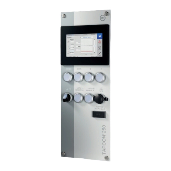
4 Product description 4.4.1 Display, operating elements and front interface Figure 5: TAPCON®250 display 1 Display 2 RIGHT cursor Navigate to the right in the menu 3 LEFT cursor Navigate to the left in the menu 4 Front interface RJ45 Ethernet interface 5 AUTO/MANUAL key Switches between AUTO/MANUAL oper- ating mode... -
Page 27: Leds
4 Product description 9 BACK key Exit the current menu. Return to the pre- vious menu level 10 ENTER key Confirm selection Key without function if a digital input is used to switch between AUTO/ MANUAL and this is activated with the parameter Pulse type digital input set to Continuous signal. -
Page 28: Ism® Assemblies
4 Product description LED Event Illuminates as soon as a red event is present. Yellow Illuminates as soon as a yellow event is present. Blue Illuminates if there are no events or a gray event is present. 4.4.3 ISM® assemblies Figure 7: Cap rail with assemblies (single-row installation) 1 Mains unit G1 2 Communication interfaces CI... - Page 29 4 Product description Figure 8: Cap rail with assemblies (two-row installation) 1 Mains unit G1 2 Communication interfaces CI 3 CPU 4 Power supply PS 5 AO 4 6 U 3 7 I 3 8 AI 4 9 System networking BES 10 DI 16-24V 11 DI 16-110V 12 DO 8 13 CAN module 14 RJ45 interface module...
- Page 30 4 Product description 4.4.3.1.1 System networking COM-ETH The COM-ETH assembly provides you with 5 Ethernet interfaces. Figure 9: COM-ETH assembly 4.4.3.1.2 CPU (central processing unit) The CPU assembly is the central processing unit for the device. It contains the following interfaces: ▪ Serial interface RS485/422 (electrically isolated, X4) ▪...
- Page 31 4 Product description 4.4.3.1.3 G1 power supply The G1 assembly provides the energy supply of the product. Figure 11: G1 assembly 4.4.3.1.4 Power supply PS The PS assembly contains the power supply unit for supplying power to the ISM® assemblies. The RY LED signals that the assembly is ready for opera- tion.
- Page 32 4 Product description 4.4.3.1.5 Digital inputs DI 16-24 V The DI 16-24V assembly has 16 digital inputs with a nominal voltage of 24 V DC. The RY LED signals that the assembly is ready for operation. Figure 13: DI 16-24V assembly 4.4.3.1.6 Digital inputs DI 16-110 V The DI 16-110V assembly has 16 digital inputs with a nominal voltage of 110 V DC/AC.
- Page 33 4 Product description 4.4.3.1.7 Digital outputs DO 8 The DO 8 assembly provides you with 8 digital outputs (relays). The RY LED signals that the assembly is ready for operation. Figure 15: DO 8 assembly 4.4.3.1.8 Analog inputs AI 4 The AI 4 assembly provides you with 4 analog inputs for measuring the cur- rent (-20...+20 mA) or voltage (-10...+10 V) of analog sensors.
- Page 34 4 Product description 4.4.3.1.9 Analog outputs AO 4 The AO 4 assembly provides you with 4 analog outputs for issuing measure- ment values (-20...+20 mA, -10...+10 V). The RY LED signals that the as- sembly is ready for operation. Figure 17: AO 4 assembly 4.4.3.1.10 Voltage measurement U 3 The U3 assembly is used for measuring 1-phase voltage.
- Page 35 4 Product description 4.4.3.1.11 Current measurement I 3 The I 3 assembly is used for measuring 1-phase voltage and current. The RY LED signals that the assembly is ready for operation. Figure 19: I 3 assembly 4.4.3.1.12 System networking BES The BES assembly is a bus extension module and extends the device by one additional bus rail with additional assemblies.
- Page 36 4 Product description 4.4.3.1.13 PE terminal Figure 21: PE terminal 4.4.3.1.14 System networking MC 2-2 The MC 2-2 assembly is a media converter, which converts 2 electrical con- nections (RJ45) to one fiber-optic cable connection each. Each is converted independently of the other. The following interfaces are available: ▪...
-
Page 37: Connections And Fuses
4 Product description 4.4.4 Connections and fuses The connections are located on the rear of the device. You will find more in- formation on the connections in the Technical data [►Section 13, Page 180] section. Figure 23: Rear 1 WEB panel Ethernet M12 2 WEB panel USB 3 Customer connection 4 Strain relief... -
Page 38: Nameplate
4 Product description 4.4.5 Nameplate Figure 24: Nameplate on the rear of the device 4.4.6 Safety markings Warning of a danger point. Read the information given in the product oper- ating instructions. 4.4.7 Connection diagram and grounding screw Figure 25: Connection diagram/grounding screw 1 Grounding screw and strain relief ®... -
Page 39: Visualization
4 Product description 4.4.8 Visualization 4.4.8.1 Main screen Home Figure 26: Home 1 Secondary navigation or naviga- 2 Primary navigation tion path 3 Status bar 4 Display area ® Maschinenfabrik Reinhausen GmbH 2022 8595028/00 EN TAPCON 250... - Page 40 4 Product description Measured values/display Figure 27: Measured values 1 Transformer name (can be edited) 2 Tap position 3 Actual measured values: Voltage, control deviation with correction, current, power factor ® TAPCON 250 8595028/00 EN Maschinenfabrik Reinhausen GmbH 2022...
- Page 41 4 Product description Desired values/actual values/delay time Figure 28: Display 1 Upper limit of bandwidth 2 Delay time T1/T2 3 Display of the measured voltage 4 Lower limit of bandwidth and corrected voltage (correction due to compensation or parallel operation) 5 Desired value 4.4.8.2 Operating concept You can operate the device using the controls on the front panel or using the web-based Intuitive Control Interface visualization on a PC.
- Page 42 4 Product description Logging in, logging out and changing users The control of access rights to device settings and parameters is user- based. Several users can log in at the same time via the visualization and access the device. If you want to operate the device via the controls and visualization at the same time, you have to log in on the device and via the visualization.
- Page 43 4 Product description Entering a value 1. Use to select the value field and press ð If operating via the front panel, the numerical keypad appears. Figure 29: Entering a value 2. Enter the desired value and confirm with 3. Press the Accept button to save the modified parameter. Entering text 1.
- Page 44 4 Product description Parameter search You can use the quick search function in the parameter menu to search for a parameter. Enter the name of the desired parameter in the Search entry field. Figure 31: Quick search Expert mode The device has an expert mode for entering the parameters. You can enter the parameters directly on the overview screen of the respective menu in this mode.
- Page 45 4 Product description To activate the expert mode, proceed as follows: 1. Go to Settings > Parameters. 2. Select the Expert mode checkbox. ð Expert mode is active. Hiding/showing parameters Depending on how you set the parameters, the device will hide or show ad- ditional parameters related to this function.
-
Page 46: Packaging, Transport And Storage
5 Packaging, transport and storage 5 Packaging, transport and storage 5.1 Suitability, structure and production The goods are packaged in a sturdy cardboard box. This ensures that the shipment is secure when in the intended transportation position and that none of its parts touch the loading surface of the means of transport or touch the ground after unloading. -
Page 47: Storage Of Shipments
5 Packaging, transport and storage Visible damage If external transport damage is detected on receipt of the shipment, proceed as follows: ▪ Immediately record the transport damage found in the shipping docu- ments and have this countersigned by the carrier. ▪... -
Page 48: Mounting
6 Mounting 6 Mounting DANGER Electric shock! Risk of fatal injury due to electrical voltage. Always observe the following safety regulations when working in or on electrical equipment. ► Disconnect the equipment. ► Lock the equipment to prevent an unintentional restart. ►... -
Page 49: Minimum Distances
6 Mounting 6.2 Minimum distances NOTICE Damage to the device! Insufficient circulation of ambient air can result in damage to the device due to overheating. ► Keep the ventilation slots clear. ► Ensure sufficient distance to neighboring components. ► Only mount device in horizontal position (ventilation slots are at the top and bottom). - Page 50 6 Mounting Dimensions for the control panel cutout B: 149.2 mm (5.87 in) Figure 34: Dimensions for the cutout 1. Cut out the section for the control panel. Figure 35: Cutting out the section for the control panel ® TAPCON 250 8595028/00 EN Maschinenfabrik Reinhausen GmbH 2022...
-
Page 51: Fastening The Cap Rail
6 Mounting 2. Slide the device into the cutout from the front and secure using the recom- mended screws. Figure 36: Inserting and screwing in the device ð The device is mounted and can be wired up. 6.3.2 Fastening the cap rail The cap rail is required to mount a bus bar or a device's remote assemblies in a control cabinet. -
Page 52: Installing Modules In The Control Cabinet
6 Mounting Electric shock! WARNING Risk of fatal injury due to electrical voltage if the cap rail is not connected to the protective ground. ► Connect the cap rail to the protective ground securely (e.g. with a protec- tive conductor line-up terminal). ►... - Page 53 6 Mounting Mounting the cap rail in the control cabinet ► Insert the cap rail into the control cabinet and secure it using the 4 self- tapping screws supplied (tightening torque 4 Nm). Figure 38: Example of a cap rail with mounted assemblies Mounting modules on your own cap rail WARNING Electric shock!
- Page 54 6 Mounting 1. Latch the bus socket onto the cap rail. Figure 39: Bus connector on cap rail 2. Push the module onto the bus connector. Figure 40: Module on bus connector ð The locking latches latch into place on the bus socket or cap rail. ®...
- Page 55 6 Mounting Figure 41: Latching locking latches ► WARNING! A faulty connection to the protective ground can lead to an electric shock in the event of faults. Ensure that the module latches in correctly. ® Maschinenfabrik Reinhausen GmbH 2022 8595028/00 EN TAPCON 250...
-
Page 56: Connecting The Device
6 Mounting 6.4 Connecting the device WARNING Electric shock! Connection errors can lead to death, injury or property damage. ► Ground the device with a protective conductor using the grounding screw on the housing. ► Note the phase difference of the secondary terminals for the current transformer and voltage transformer. -
Page 57: Electromagnetic Compatibility
6 Mounting Excessive line capacitance can prevent the relay contacts from interrupting the contact current. In control circuits operated with alternating current, take into account the effect of the line capacitance of long control cables on the function of the relay contacts. If you want to route Ethernet connections from a control cabinet or building, we recommend using fiber-optic cables (in accordance with the IEC 61850-90-4 recommendation). - Page 58 6 Mounting 6.4.2.1 Wiring requirement of installation site Note the following when selecting the installation site: ▪ The system's overvoltage protection must be effective. ▪ The system's ground connection must comply with all technical regula- tions. ▪ Separate system parts must be joined by a potential equalization. ▪...
- Page 59 6 Mounting Using single conductors may limit the effectiveness of the shielding. Con- nect close-fitting shielding to cover all areas. Figure 43: Recommended connection of the shielding 1 Connection of the shielding via a 2 Full-surface connection of the single conductor shielding 6.4.2.3 Wiring requirement in control cabinet Note the following when wiring in the control cabinet:...
-
Page 60: Connecting Cables To The System Periphery
6 Mounting ▪ The cap rails used must be networked with each other and connected to the system ground over a large area. ▪ The device must be grounded on the provided screw, the protective ground connection, with a ground strap (cross-section of min. 8 mm² (0.32 in Figure 44: Ground strap connection 6.4.3 Connecting cables to the system periphery... -
Page 61: Connecting Scada
6 Mounting NOTICE Damage to the device! If you connect the CAN bus cable to devices with different potentials, cur- rent may flow across the shielding. This current may damage the device. ► Connect the devices to a potential equalization rail to equalize the poten- tial. -
Page 62: Wiring Voltage Measurement/Current Measurement Ui
6 Mounting 6.4.5.1 Serial interface RS485 Data cable The device is connected via the RS485 interface (COM2) via the CPU as- sembly module (X4) or PCB connector (see Technical data). 1. Connect the RS485 interface COM-X1 on the interface module and the in- terface CPU-X4 together using the patch cable. -
Page 63: Wiring The Mc 2-2/Sw3-3 Assembly
6 Mounting 1. Voltage measurement: Feed the wires into the terminals in accordance with the connection diagram and fasten them using a screwdriver. 2. Current measurement: Feed the wires into the terminals in accordance with the connection diagram and fasten them using a screwdriver. 6.4.7 Wiring the MC 2-2/SW3-3 assembly 1. - Page 64 6 Mounting 2. Remove the SFP module dust plug. Figure 46: Removing the dust plug 3. Insert the fiber-optic cable into the SFP module. Figure 47: Inserting the fiber-optic cable ® TAPCON 250 8595028/00 EN Maschinenfabrik Reinhausen GmbH 2022...
- Page 65 6 Mounting 4. Insert the network cable. Figure 48: Inserting the network cable Voltage supply Connect the MC2-2/SW3-3 assembly to the voltage supply of the voltage supply unit: 1. Guide the leads into the respective plug terminals for the voltage supply and fasten them using a screwdriver.
-
Page 66: Wiring Analog Inputs Ai
6 Mounting 2. Insert and fasten the plug into the respective "24V DC" slot. Figure 50: Fastening the 24 V DC plug 6.4.8 Wiring analog inputs AI NOTICE Damage to the device and sensors! Incorrectly connected and configured analog inputs/outputs may result in damage to the device and sensor. -
Page 67: Wiring Digital Inputs Di
6 Mounting Block diagram and wiring versions CAN bus AI 4 Controller Reinforced insulation Connection of a 2- Connection of a 4- Connection of a 3- Connection of a 4- conductor measuring conductor measuring conductor measuring conductor measuring transducer with current transducer with voltage transducer with current transducer with current... -
Page 68: Wiring Digital Outputs Do
6 Mounting 6.4.10 Wiring digital outputs DO CAN bus DO 8 Controller Reinforced insulation 1-pole with 1-pole with connected connected 2-pole positive negative Figure 52: Block diagram for digital outputs 1. Feed the wires into the terminal of the plug in accordance with the con- nection diagram and fasten them using a screwdriver. - Page 69 6 Mounting Conductor cross-section For the power supply circuit, use a conductor cross-section suitable for the miniature circuit breaker that you have selected, but at least 1.5 mm (AWG 15). Connecting the power supply ► Connect the power supply in accordance with the connection diagram. ®...
-
Page 70: Performing Tests
► Prior to commissioning, check the supply voltage and the measured volt- age. ► Connecting the device to mains. ð The display shows the MR logo and then the operating screen. ð The voltage display LED on the top right on the device's display lights ®... -
Page 71: Initial Steps
7 Initial steps 7 Initial steps NOTICE Damage to device and system periphery An incorrectly connected device can cause damage to the device and sys- tem periphery. ► Check the entire configuration before commissioning. As soon as the device has powered up and the start screen is displayed, you will be asked to make the following settings: 7.1 Establishing connection to visualization A connection to the visualization can be established using two interfaces:... - Page 72 7 Initial steps Establishing a connection via front interface 1. Remove the interface cover on the front of the device. 2. Connect the PC and the device via the front interface using an Ethernet cable (RJ45 plug). Figure 53: Establishing a connection via front interface 3.
- Page 73 ► Select in the status line. ð The operating instructions will be downloaded. The document is also available for download in the MR Customer Portal and on our website www.reinhausen.com. ® Maschinenfabrik Reinhausen GmbH 2022 8595028/00 EN TAPCON 250...
-
Page 74: Commissioning
4. Follow the on-screen instructions. Once you have entered all of the parameters relevant to commissioning, continue with the function test. 8.2 Performing tests Please contact Maschinenfabrik Reinhausen GmbH (MR) if any aspect of the tests is not clear. ® TAPCON 250... -
Page 75: Ground Test
8 Commissioning 8.2.1 Ground test For commissioning, carry out a ground test (check of the protective bonding impedance) in accordance with IEC 61010-1. Observe the following informa- tion when testing: ▪ Test current: 2 times the rated current of the overcurrent protection device in the supply line. - Page 76 8 Commissioning NOTICE Damage to the device! A dielectric test with a test voltage that is greater than the maximum permit- ted test voltage can lead to the device being damaged. ► Perform the dielectric test with a test voltage that is less than or equal to the maximum permitted test voltage.
-
Page 77: Function Tests
8 Commissioning 8.3 Function tests Before switching from manual mode to auto mode, Maschinenfabrik Rein- hausen recommends carrying out function tests. These function tests are de- scribed in the following sections. Note the following points for all function tests: ▪ You have to change the pulse type [►Page 166] to time-controlled switch- ing pulse in order to activate the operating keys. - Page 78 8 Commissioning 4. Select the Measured values menu item to display the operating values for current and power and compare them with the values of the operation measurement instruments. 5. Control the on-load tap-changer manually using the keys until the measured voltage U reaches the desired voltage U ("de- actual...
-
Page 79: Checking Parallel Operation
8 Commissioning 8.3.3 Checking parallel operation To ensure that parallel operation functions correctly, the device must be commissioned in independent mode. Make sure that the conditions below have been met. ▪ All devices are set to the same operating parameters for "desired value" and "delay time T1"... - Page 80 8 Commissioning 9. Press to select auto mode on all devices. ð All devices return the on-load tap-changers to the original tap positions. If an on-load tap-changer does not switch back to its original tap position, you have to increase the circulating reactive current sensitivity. If one of the on-load tap-changers switches one or more tap positions higher and the other switches the same amount lower, you need to reduce the circulating reactive current sensitivity.
- Page 81 8 Commissioning If one TAPCON® or all of the TAPCON® units indicate Circulating reactive current blocking limit exceeded even though the control inputs are correctly connected for all TAPCON® units, all of the TAPCON® units block. This could be due to various causes. Further information is given in the chapter Troubleshooting [►Section 11, Page 173].
- Page 82 8 Commissioning 3. Compare the tap position displays of master and follower . All de- vices must display the same tap position. If this is not the case, switch all devices to the same tap position. Figure 55: Comparing the tap position 1 Master 3 Tap position display 2 Follower...
- Page 83 8 Commissioning 14. Press on the master and follower to select manual mode. 15. Press on the master and follower to manually set the desired step. ð The function tests for the tap synchronization method are complete. Installation and commissioning of the device is complete. ®...
-
Page 84: Operation
9 Operation 9 Operation This chapter describes all the functions and setting options for the device. 9.1 System 9.1.1 General You can set general parameters in this menu item. 9.1.1.1 Setting general device functions You can set general device functions with the following parameters. 1. - Page 85 9 Operation Setting Description Hardware only The device accepts commands through digital inputs. SCADA only The device accepts commands via SCADA. Hardware and SCADA The device accepts commands via digital inputs and SCADA. Table 14: Selecting remote behavior 9.1.1.2 Set up automatic logout You can change the settings so that the device of a logged-in user automati- cally logs the user out after a certain period of inactivity.
-
Page 86: Configuring The Network
9 Operation If you deactivate the service user access and lose your password for the ad- ministrator role, it is not possible to reset the administrator password. If the administrator password is lost, the device must be reset to the default set- tings. -
Page 87: Setting The Device Time
9 Operation Be sure to enter a valid network mask that is not 0.0.0.0, otherwise it will not be possible to connect to the device. Gateway address You can use this parameter to set the gateway's IP address. If you set the value to 0.0.0.0, no gateway is used. SSL/TLS encryption You can use this parameter to set whether the process for accessing the vi- sualization should be carried out over an SSL/TLS-encrypted connection. -
Page 88: Setting The Screensaver
9 Operation Time synchronization via SNTP You can use this parameter to activate time synchronization using an SNTP time server. SNTP time server You can use this parameter to enter the IP address of a SNTP time server. If you are using a time server, the device uses the time of the time server as the system time. -
Page 89: Configuring Syslog
9 Operation 1. Go to Settings > Parameters > System > Screensaver. 2. Select the desired parameter. 3. Set the parameter. 4. Press the Accept button to save the modified parameter. Screensaver If you activate this function, the device fully switches off the display when the adjustable waiting period has expired if no key is pressed. - Page 90 9 Operation Syslog standard You can use this parameter to adjust the transmission process and the for- mat for the syslog messages. You can select the following options: Standard Transport Message format RFC 5425 (recom- RFC 5424 mended) RFC 5426 RFC 6587 RFC 3164 RFC 3164 Table 17: Syslog standard If you use the standard RFC 5245 (TLS), you have to import the root certifi- cate and the client certificate with the corresponding key to the syslog...
-
Page 91: Scada
9 Operation Severity level Description Warning state Warning Notice state Notice Information state Info Debug state Debug Table 18: Severity levels 9.1.6 SCADA The following section describes how you can configure the device for con- nection to a control system (SCADA). You can download the data points with the help of the export manager. - Page 92 9 Operation 9.1.6.2 Configuring IEC 60870-5-101 If you want to use the IEC 60870-5-101 control system protocol, you must set the following parameters. 1. Go to Settings > Parameters > System > IEC 60870-5-101. 2. Select the desired parameter. 3. Set the parameter. 4.
- Page 93 9 Operation No. of information object address octets You can use this parameter to set how many octets are provided for the in- formation object address. Number of cause of transmission octets You can use this parameter to set how many octets are provided for the cause of transmission.
- Page 94 9 Operation 9.1.6.3 Configuring IEC 60870-5-104 If you want to use the IEC 60870-5-104 control system protocol, you must set the following parameters. Also refer to the section Configuring the net- work. 1. Go to Settings > Parameters > System > IEC 60870-5-104. 2.
- Page 95 9 Operation 4. Press the Accept button to save the modified parameter. Modbus type You can use this parameter to set the Modbus type. You can select the fol- lowing options: ▪ RTU ▪ TCP Modbus address You can use this parameter to set the Modbus address. TCP port You can use this parameter to set the TCP port.
- Page 96 9 Operation 9.1.6.5 Configuring DNP3 If you would like to use the DNP3 control system protocol, you must set the parameters listed below. Also refer to the section Configuring the network if you want to use the DNP3 via TCP. 1.
-
Page 97: Setting The Measured Value Recorder
9 Operation Unsolicited messages You can use this parameter to set whether the device is to support unso- licited messages. If you activate unsolicited messages, the device sends a message via the control system every time a value is changed. Repetition of unsolicited messages You can use this parameter to set how often the device is to send an unso- licited message until it receives a response from the DNP3 master. -
Page 98: Linking Signals And Events
9 Operation Figure 56: Recorder 1. Go to Settings > Parameters > System > Recorder. 2. Select the desired parameter. 3. Set the parameter. 4. Press the Accept button to save the modified parameter. Average value interval You can use this parameter to set the average value interval of the mea- sured value recorder for electrical measured variables (current, voltage, phase angle etc.). - Page 99 9 Operation The digital inputs available are each permanently linked to a General pur- pose input event message and the control system commands available are each permanently linked to a Generic SCADA command event message for this purpose. Input/command Event message Digital input 1 General purpose input 1 Digital input 2...
- Page 100 9 Operation Independent regulation If the assigned event is active, the device activates the independent regula- tion independent mode. Master parallel operation method If the assigned event is active, the device activates the master parallel oper- ation method. Follower parallel operation method If the assigned event is active, the device activates the follower parallel oper- ation method.
- Page 101 9 Operation Activate desired value 5 If the assigned event is active, the device activates the desired value 5. 9.1.8.2 Digital inputs The device features the option of assigning the following functions to the dig- ital inputs. Description I: Desired value setting release If the input is active, the device activates the release of the desired value.
- Page 102 9 Operation Description I: K2 feedback If the input is active, the device activates the input feedback K2. I: TDSC® off If the input is active, the device activates the input TDSC® off. I: TDSC® on If the input is active, the device activates the input TDSC®...
- Page 103 9 Operation Description O: Desired value 5 If a signal is present at the input, the de- vice activates desired value 5. O: Function monitoring If a signal is present at the input, the de- vice activates function monitoring. O: Collective error If a signal is present at the input, the de- vice activates the event active function.
- Page 104 9 Operation Description O: Bandwidth > If a signal is present at the input, the de- vice activates the function bandwidth value below limit. O: Desired value 1 If a signal is present at the input, the de- vice activates desired value 1. O: Desired value 2 If a signal is present at the input, the de- vice activates desired value 2.
- Page 105 9 Operation Description O: AVR Local/Remote If a signal is present at the input, the de- vice activates the LOCAL/REMOTE function. O: Status Ok If a signal is present at the input, the de- vice activates the device status. O: Lower If a signal is present at the input, the de- vice activates the LOWER function.
-
Page 106: Configuring Analog Inputs
9 Operation 9.1.8.5 Linking status messages You can link each event with a status message. The device provides 10 generic status messages for this purpose. When you link a message to an event, the device sets the data point to "On" when the event occurs. When the event stops, the device sets the data point to "Off". - Page 107 9 Operation Correction factor and offset Setting a correction offsets systematic errors of the analog signals. The cor- rection is determined by multiplying a factor by the sum of the offset. The minimum and maximum values of the function values apply as a limit value for the correction.
- Page 108 9 Operation Property Options Decimal places Set up to three decimal places. Minimum/maximum Set the minimum and maximum values of the sensor, e.g. value with a 4...20 mA signal, the corresponding measured value for 4 mA and the corresponding value for 20 mA. Correction factor Set the correction factor (m) for the correction of the func- tion value (x).
-
Page 109: Configuring Digital Inputs And Outputs
9 Operation 9.1.10 Configuring digital inputs and outputs Upon delivery, the configurable digital inputs and outputs of the device are configured as follows: ▪ Input: High active ▪ Output: N/O contact (NO) You can change this configuration if necessary. Ensure that the configuration of the digital inputs and outputs is suitable for the functions used. -
Page 110: Event Management
9 Operation Configuring DIOs 1. Go to menu item Settings > DIO configuration. 2. Where necessary, select the buttons ▲ or ▼ to sort the properties in a column alphabetically. 3. Configure the properties as desired. 4. Press the Accept button. 5. - Page 111 9 Operation Column Description Time Date and time of event (DD-MM-YYYY, HH:MM:SS/ms) Event coming/going: Event coming Event going Table 24: Event memory 1. Go to Events. 2. Press the Log button. Figure 58: Event memory Filtering events 1. Press the Filter button. 2.
-
Page 112: User Administration
9 Operation To export the events, proceed as follows: ü First connect via PC. 1. Click on the Export button. 2. Select the desired option for data transmission. ð The data is exported. 9.1.12 User administration User administration is based on a system of roles. You must assign a role to every user. - Page 113 9 Operation Option Description Parameter list Parameter list with descriptive text and values (min, max, cur- rent). Event list Complete list of all possible events. SCADA configu- Control system configuration ration Operating in- Operating instructions, protocol specifications. structions Settings Configuration of parameters and events. Security log Logbook of all instances of access and changes relating to secu- rity.
- Page 114 9 Operation 9.1.15.2 Importing data You can import the following data: Option Description System image Complete image of the system (software and configura- tion), with or without history. Settings All device settings: ▪ Parameter settings ▪ Event settings ▪ Administrative settings (users, access rights) The settings can also be imported from another device.
- Page 115 9 Operation 9.1.15.3 Importing server certificate update The product allows you to import your own trustworthy certificates. The interfaces do not use a DHCP server. Therefore, you must assign a static IP address to your PC. To do this, observe the following configuration example: ▪...
- Page 116 9 Operation Disconnecting the network drive Upon successful import, the drive is to be disconnected from the PC and the network properties reset to the standard. 1. Select the network drive and right-click on Disconnect network drive. 2. Reset the network connection properties to standard. 3.
-
Page 117: Power Grid
9 Operation 9.2 Power grid 9.2.1 Transformer data The transformation ratios and measuring set-up for the voltage and current transformers used in the system can be set with the following parameters. The device uses this information to calculate the corresponding measured values on the primary side of the current transformer (and therefore the transformer) from the recorded measured values. - Page 118 9 Operation Voltage-transformer circuit You can use this parameter to set your voltage transformer's circuit. You can select the following options: Option Description 1 Ph phase voltage Measurement in 1-phase grid between the conductor and neutral conductor. 3 Ph differential voltage Measurement in 3-phase grid between 2 conductors 3 Ph phase voltage...
- Page 119 9 Operation 9.2.1.2.1 1-phase measurement Circuit 1-A Figure 59: Circuit 1-A ▪ The voltage transformer VT is connected to the phase conductor and the neutral conductor. ▪ The current transformer CT is looped into the phase conductor. ▪ The voltage U and current I are in phase.
- Page 120 9 Operation ▪ The voltage transformer VT is connected to the phase conductor L1 and the neutral conductor. ▪ The current transformer CT is looped into the phase conductor L1. ▪ The voltage U and current I are in phase. ▪...
- Page 121 9 Operation If you use this circuit, set the device as follows: Parameter Option Voltage-transformer circuit 3 Ph differential voltage Current-transformer circuit 3 Ph total current Phase angle correction 0° Table 31: Circuit 1-C Circuit 1-D Figure 62: Circuit 1-D ▪ The voltage transformer VT is connected to the phase conductors L1 and ▪...
- Page 122 9 Operation Circuit 1-E Figure 63: Circuit 1-E ▪ The voltage transformer VT is connected to the phase conductors L1 and ▪ The current transformer CT is looped into the phase conductor L2. ▪ The current I is ahead of voltage U by 30°.
-
Page 123: Voltage Monitoring
9 Operation ▪ The voltage transformer VT is connected to the phase conductors L1 and ▪ The current transformer CT is looped into the phase conductor L1. ▪ The current I lags behind voltage U by 30°. This corresponds to a phase shift of +30°... - Page 124 9 Operation Delay time Event duration H Hysteresis 1. Go to Settings > Parameters > Grid > Voltage monitoring. 2. Select the desired parameter. 3. Set the desired parameter. 4. Press the Accept button to save the modified parameter. You can set additional parameters for each limit value: Mode You can use this parameter to set which limit value you would like to use: ▪...
-
Page 125: Current Monitoring
9 Operation Setting Behavior Auto blocking position- The automatic control does not perform a tap-change operation in the direction of a lower tap position (posi- tion-). You can still perform a tap-change operation in the di- rection of a lower tap position (position-) in manual mode. - Page 126 9 Operation If the measured value is higher than the upper limit (> or >>) or lower than the lower limit (< or <<), the device transmits an event message. I>> I> I< I<< Figure 66: Example of current monitoring with the limit value I> being exceeded I>>...
-
Page 127: Power Monitoring
9 Operation Delay time You can use this parameter to set the delay time in order to delay the issuing of the event message. Reaction You can use this parameter to set the behavior of the device if the measured value is higher than the upper limit (>... - Page 128 9 Operation Hysteresis You can use this parameter to set the hysteresis. You can use this to avoid the unnecessary generation of messages if the measured value fluctuates around a threshold value. Delay time You can use this parameter to set the delay time in order to delay the issuing of the event message.
-
Page 129: Power Flow Monitoring
9 Operation 9.2.5 Power flow monitoring A reversal of power flow occurs if the active power is negative. You can set the following parameters for this: ▪ Hysteresis ▪ Delay time ▪ Behavior 1. Go to Settings > Parameters > Grid > Power flow monitoring. 2. - Page 130 9 Operation Behavior for reversal of power flow You can use this parameter to set the behavior in the event of a reversal of power flow. You can select the following options: Setting Behavior ▪ The negative power flow is ignored. ▪...
-
Page 131: Monitoring Settings
9 Operation 9.2.6 Monitoring settings Monitoring U < 30 V You can use this parameter to activate events and function monitoring. You can select the following options: Setting Behavior Activate Monitoring is activated, even if the measured voltage U > 30 V. Deactivate Monitoring is activated. - Page 132 9 Operation If you wish to operate several devices in parallel operation with existing de- vices, you have to activate the TAPCON® 2xx retrofit function on each de- vice. Figure 67: Parallel operation of 2 devices with one TAPCON® 2xx. The TAPCON® 2xx retrofit function must be active on both devices.
- Page 133 9 Operation If you activate this parameter, you have to reverse the prefix of the "Phase angle correction" parameter for the transformer data (from - to + or from + to ® Maschinenfabrik Reinhausen GmbH 2022 8595028/00 EN TAPCON 250...
-
Page 134: On-Load Tap-Changer Regulator
9 Operation 9.3 On-load tap-changer regulator 9.3.1 Voltage regulation All of the parameters required for the control function are described in this section. 1. Go to Settings > Parameters > On-load tap-changer regulator > Volt- age regulation. 2. Select the desired parameter. 3. - Page 135 9 Operation 1. Go to Settings > Parameters > On-load tap-changer > Voltage regula- tion > Change remote desired value setting. 2. Select the desired option in the list. 3. Press the Accept button to save the modified parameter. Selecting a desired value You can use this parameter to select the desired value used for control.
- Page 136 9 Operation You have to set the parameters for both winding 1 (W1) and winding 2 (W2). Setting desired value 1 1. Go to Settings > Parameters > Grid > Control > Desired value. 2. Enter the desired value. 3. Press the Accept button to save the modified parameter. Setting max.
- Page 137 9 Operation Parameter Function Settings (see diagram below) : Active power at max. de- Set maximum active power value above which the 20.0 MW sired value power-dependent desired value is to attain the maxi- mum value U : Active power at min. desired Set minimum active power value below which the -20.0 MW value...
- Page 138 9 Operation Response to value falling below active power P If the measured active power P falls below the set parameter P , the meas value U is adopted as the desired value. Response to a measured active power P = 0 MW: meas If the measured active power P...
- Page 139 9 Operation To activate/deactivate TDSC using parameters, proceed as follows: 1. Go to Settings > Parameters > Control > Activate TDSC. 2. Select the desired option. 3. Press the Accept button to save the modified parameter. TDSC Umax/Umin You can use these parameters to set the maximum and minimum desired value.
- Page 140 9 Operation The bandwidth must always be greater than the following value: n - 1 ± B ≥ 0,6× × 100 % Step voltage of tap position n-1 Step voltage of tap position n Nominal voltage The following transformer values are used to determine the minimum band- width: Nominal voltage U = 11000 V...
- Page 141 9 Operation change command is issued after expiration of the set delay time T1. The on-load tap-changer carries out a tap-change in a raise or lower direction to return to the tolerance bandwidth. Figure 71: Behavior of the control function with delay time T1 1 Upper limit of bandwidth 4 Set delay time T1 2 Desired value...
- Page 142 9 Operation The following requirements must be noted to set delay time T2: ▪ The delay time T2 must be greater than the switching pulse time. ▪ The delay time T2 must be greater than the maximum operating time of the motor-drive unit.
-
Page 143: Line Drop Compensation
9 Operation 9.3.2 Line drop compensation You can use the compensation function to compensate for the load-depen- dent voltage drop between the transformer and consumer. The device pro- vides 2 methods of compensation for this purpose: ▪ R&X compensation ▪ Z compensation 9.3.2.1 R&X compensation R&X compensation can compensate for voltage losses on the lines and therefore ensure correct voltage at the load. - Page 144 9 Operation To use R&X compensation, you have to enter the following line data: ▪ Ohmic resistance load in mΩ/m ▪ Inductive resistance load in mΩ/m ▪ Length of line in km 1. Go to Settings > Parameters > On-load tap-changer regulator > Com- pensation.
-
Page 145: Parallel Operation
9 Operation To use Z compensation, you need to calculate the voltage increase (ΔU) tak- ing the current into account. Use the following formula for this purpose: × k Load ΔU = × × 100 % Load ∆U Voltage increase Load current in A Transformer voltage at current I I Nominal current of current-trans- former connection in A... - Page 146 9 Operation ▪ The same number of switching groups ▪ For parallel operation with CAN communication: Current transformers with the same connection values must be used for all devices operating in par- allel 9.3.3.1 Parallel operation methods You can undertake parallel operation with various parallel operation meth- ods.
- Page 147 9 Operation Note that the following prerequisites must be met for the "circulating reactive current minimization" parallel operation method: ▪ You have to use current transformers with the same rated values for all transformers in parallel operation. ▪ If you wish to operate in parallel operation with existing devices, you have to activate the Retrofit TAPCON®...
- Page 148 9 Operation rection for the control deviation determined on the basis of the measurement voltage. This extra control deviation depends on how much the measured power factor deviates from the desired power factor. To use the power factor method, you need to know the conditions of your network in order to correctly set the device parameters.
- Page 149 9 Operation The master handles voltage regulation and transmits its current tap positions to all followers via the CAN bus. The followers compare the tap position re- ceived with their own tap position. If the tap position is not the same, the fol- lowers switch to the tap position received from the master.
- Page 150 9 Operation 9.3.3.2 Configuring parallel operation In the Parallel operation menu item, you can set the parameters needed for parallel transformer operation. 1. Go to Settings > Parameters > Grid > Parallel operation > . 2. Select the desired parameter. 3.
- Page 151 9 Operation 9.3.3.2.3 Assigning a CAN bus address You can use this parameter to assign a CAN bus address to the device. So that all devices can communicate using the CAN bus, each device requires a unique identifier. If the value is set to 0, then no communication takes place. 9.3.3.2.4 Setting circulating reactive current sensitivity You can use this parameter to set the influence of circulating reactive current on how the control deviation is calculated.
- Page 152 9 Operation You can determine the load stress type using the phase angle difference be- tween voltage and current. You calculate the phase angle difference as fol- lows: Figure 79: Calculation of phase angle difference φ Phase angle difference between voltage and current φ...
-
Page 153: U Bandwidth Monitoring
9 Operation If the tap difference is greater than the set maximum tap difference to the master, the follower blocks and no longer attempts to attain the master's tap position. After the set delay time for parallel operation error messages has elapsed, the follower issues the Permitted tap difference to master exceeded message. - Page 154 9 Operation Function monitoring You can use this parameter to activate function monitoring. When doing so, also observe the monitoring settings [►Page 131]. You can select the following options: Setting Behavior Function monitoring is deactivated. Only Auto Function monitoring is only active in AVR AUTO oper- ating mode.
-
Page 155: On-Load Tap-Changer
9 Operation 9.4 On-load tap-changer 9.4.1 Tap position monitoring You can set the limit value parameter for tap position monitoring: 1. Go to Settings > Parameters > On-load tap-changer > Tap position monitoring. 2. Select the desired parameter. 3. Set the desired parameter. 4. - Page 156 9 Operation 9.4.1.1 Switching interval monitoring You can use this function to monitor the typical tap-change behavior of your transformer. Furthermore, you can set the number of consecutive tap- change operations permissible in auto mode within a defined time period. You can have the following operations monitored: ▪...
- Page 157 9 Operation Event duration You can use this parameter to set how long the device is to respond with the set behavior. Behavior You can use this parameter to set the behavior of the device if the maximum permissible number of tap-change operations is exceeded: Setting Behavior Switching interval monitoring is disabled.
- Page 158 9 Operation ▪ Keep Track ▪ Decade In order to ensure proper function of the tap position capture, make sure that the inputs of the corresponding tap position capture method are acti- vated and correctly wired. To ensure that the tap position capture functions correctly, ensure that when you change the tap position capture method, the previously set DIO or AIO configurations of the tap position are deleted and set for the new tap posi- tion detection.
- Page 159 9 Operation Pos. at min. analog signal You can use this parameter to set the tap position of the on-load tap- changer corresponding to the minimum analog signal (e.g. 4 mA for 4...20 mA signal). 1. Go to Settings > Analog tap position capture > Pos. at min. analog signal.
-
Page 160: Target-Tap-Position Operation
9 Operation 13. Step 5: Press the Next button to complete calibration. ð Calibration of tap position capture using the resistor contact series has been performed successfully. 9.4.1.2.2 Keep Track In the event of a power failure on the ISM, the display value has to be ad- justed to the actual value of the tap position on the OLTC via the Keep Track parameter. -
Page 161: Information About The On-Load Tap-Changer
9 Operation 9.4.3 Information about the on-load tap-changer Under "OLTC" you can display information about the on-load tap-changer: ▪ Current tap position ▪ Total tap-change operations (operations counter) ► Go to Information > On-load tap-changer > OLTC. 9.4.4 OLTC data In this menu, you can set parameters for the on-load tap-changer (OLTC). - Page 162 9 Operation 9.4.4.1 Setting the tap position message (optional) If you issue the tap position of the on-load tap-changer via an analog output or digital outputs (BCD, gray, etc.), you can set whether the device is to use the raw value or the adjusted value for the control system in accordance with the tap position table.
-
Page 163: U Bandwidth Monitoring
9 Operation BCD tap position message You can use this parameter to set which range of values from the tap posi- tion table the device is to use for the tap position message via digital outputs (BCD). 9.4.5 U bandwidth monitoring The following limit values are monitored via bandwidth monitoring. - Page 164 9 Operation Figure 83: U bandwidth monitoring 1. Go to Settings > Parameters > On-load tap-changer regulator > U bandwidth monitoring. 2. Select the desired parameter. 3. Set the desired parameter. 4. Press the Accept button to save the modified parameter. Also refer to 2 Monitoring U <...
-
Page 165: Displaying The Minimum And Maximum Tap Position
9 Operation Delay time You can use this parameter to set the delay time in order to delay the issuing of the event message. 9.4.6 Displaying the minimum and maximum tap position You can display the minimum and maximum tap position reached and the corresponding time. -
Page 166: Motor-Drive Unit And Control Cabinet
9 Operation 9.5 Motor-drive unit and control cabinet 9.5.1 Control of the motor-drive unit The following parameters let you configure control of the motor-drive unit. You can set the following: ▪ Switching pulse ▪ Motor runtime ▪ Switching direction Figure 85: Motor control unit ►... - Page 167 9 Operation Continuous pulse Selecting the "Continuous pulse" option causes the device to issue the switching pulse in AVR Auto operating mode until the measured value is back within the bandwidth. In AVR Manual operating mode, the device is- sues the switching pulse for as long as you press the key.
- Page 168 9 Operation Switching pulse pause You can use this parameter to set the switching pulse pause between 2 switching pulses. The device can only issue another switching pulse once the switching pulse pause has elapsed. 9.5.1.2 Setting motor runtime monitoring The motor-drive unit's runtime can be monitored by the device.
- Page 169 9 Operation 4. Press the Accept button to save the modified parameter. U switching direction You can use this parameter to set the switching direction for voltage regula- tion. You can use this to adjust the behavior of the device based on how your on-load tap-changer and motor-drive unit are configured.
- Page 170 9 Operation 4. Press the Accept button to save the modified parameter. Switching pulse type You can use this parameter to toggle the switching pulse between a continu- ous pulse or a time-controlled switching pulse. Continuous pulse Selecting the "Continuous pulse" option causes the device to issue the switching pulse in AVR Auto operating mode until the measured value is back within the bandwidth.
- Page 171 9 Operation Switching pulse time You can use this parameter to set the maximum duration of the switching pulse. The switching pulse resets after the switching pulse time has elapsed or if the device receives the Motor running signal beforehand or the tap posi- tion is changed.
-
Page 172: Maintenance And Care
10 Maintenance and care 10 Maintenance and care 10.1 Cleaning the device You can clean the device with a dry cloth. 10.2 Maintenance Maintenance of the monitoring system is not required However, check the state and functionality of the monitoring system as part of maintenance work on the transformer. -
Page 173: Fault Elimination
11 Fault elimination 11 Fault elimination This chapter describes how to rectify simple operating faults. 11.1 General faults Characteristics/details Cause Remedy No function No power supply. Check the power supply. ▪ Power supply LED does not Fuse tripped. Contact Maschinenfabrik Reinhausen GmbH. light up No function Configuration error... -
Page 174: Unwanted On-Load Tap-Change Operation
11 Fault elimination Characteristics/details Cause Remedy Bandwidth set too high Determine the recommended bandwidth. Parallel operation active. Device is follower in parallel oper- No error. If necessary, deactivate parallel opera- ation. tion. CAN bus communication failure "Auto blocking" behavior is set. Check configuration. -
Page 175: Incorrect Measured Values
11 Fault elimination Web browser Characteristics/details Cause Remedy Connection to the visualization Connection cable defective. Check connection cable. cannot be established. SSL encryption active. Accept SSL certificate in browser. Call up IP address using https://. Deactivate SSL encryption. PC not in same subnet as visual- Check the setting of IP addresses of the device ization. -
Page 176: Parallel Operation Faults
11 Fault elimination 11.6 Parallel operation faults Characteristics/details Cause Remedy Problem with CAN bus. Device incorrectly connected. Check connections. ▪ Device not listed. Connect as shown in the connection diagram. Devices have the same CAN bus Set different CAN bus addresses. address. -
Page 177: Tap Position Capture Incorrect
11 Fault elimination 11.7 Tap position capture incorrect Characteristics/details Cause Remedy Position indicator incorrect. Incorrect wiring. Check wiring. ▪ Leading sign incorrect. Connect as shown in the connection diagram. Minimum value of the analog in- Check parameters. put signal not configured cor- rectly. - Page 178 11 Fault elimination Please provide answers to the following questions: ▪ Has the software been updated? ▪ Has there previously been a problem with this device? ▪ Have you previously contacted Maschinenfabrik Reinhausen about this is- sue? If yes, then who was the contact? ®...
-
Page 179: Disposal
12 Disposal 12 Disposal Observe the national requirements applicable in the country of use. ® Maschinenfabrik Reinhausen GmbH 2022 8595028/00 EN TAPCON 250... -
Page 180: Technical Data
13 Technical data 13 Technical data 13.1 TC250 technical data 13.1.1 Display elements Display 5″ TFT colour display LEDs 3 LEDs for operation display and messages ▪ POWER, AVR STATUS, ALARM 13.1.2 Materials Front Aluminum, plastic 13.1.3 Dimensions Front panel display: 161.9 mm x 419.1 mm x 2.3 mm W x H x D Mating connector: 20 mm... -
Page 181: Voltage Measurement And Current Measurement
13 Technical data Auxiliary supply voltage AUX DC DI 24V DC for digital inputs The auxiliary supply voltage is used exclusively for detecting up to 16 float- ing contacts. Output voltage : 24 V DC ± 2% (short-circuit proof) Max. output power 120 W Overvoltage category OC III... -
Page 182: Ambient Conditions
13 Technical data Overload capacity short-term 120 A/1 s (directly on the test tap of the measure- ment card) Surge test voltage 4 kV, measurement category III 13.1.6 Ambient conditions Operating temperature -25...+70°C Storage temperature -30...+85°C Relative humidity 5...95%, condensation not permitted Maximum installation alti- <3,000 m above mean sea level tude Minimum clearance to... - Page 183 13 Technical data Assemblies: IEC 60255-21-1 or IEC 60068-2-6 vibra- tion G1, G2, PS, U3, I3, BES, DI, DO, AI, AO, MC2-2, display, CPU, COM-ETH IEC 60255-21-2 or IEC 60068-2-27 shock Assemblies: IEC 60255-21-3 or IEC 60068-3-3 seis- PS, U3, I3, BES, DI, DO, AI, AO, MC2-2, CPU, COM-ETH ®...
-
Page 184: Ism® Assemblies Technical Data
13 Technical data 13.2 ISM® assemblies technical data 13.2.1 System networking COM-ETH COM-ETH Interfaces 5x Ethernet via RJ45 RJ45 Max. 100 m (per section) 10/100 Mbps Redundancy protocols HSR, PRP, RSTP Table 59: COM-ETH assembly technical data Interface Description TxD+ TxD- RxD+ RxD- Table 60: Connectors X1…X5 (Ethernet) 13.2.2 Central processing unit Processor... - Page 185 13 Technical data Response behavior of the watchdog/error relay: Error relay Watchdog relay Power off Startup Ready (no error pending) Ready (pending error) ON: Relay is energized OFF: Relay is de-energized Interfaces Interface Description ER_NO ER_NC ER_COM WD_NO WD_NC WD_COM Table 61: Plug terminal CPU:X1 Interface X2, X3 Description...
-
Page 186: System Networking Bes
13 Technical data Interface X4 Description TXD+/RXD+ TXD-/RXD- Table 63: Serial interface RS485 CPU:X4 Interface X5 Description DTR (O) DCD (I) RXD (I) TXD (O) VCC/OUT 5 V/12 V RTS (O) CTS (I) Table 64: Serial interface RS232 CPU:X5 13.2.3 System networking BES Interfaces 2x Ethernet via RJ45 RJ45 Max. -
Page 187: Power Supply Ps
13 Technical data Interface Description Power supply (+) Not used Not used Power supply (-) Table 66: Terminal X1 Interface Description TxD+ TxD- RxD+ RxD- Table 67: Jacks X2, X3 (Ethernet) 13.2.4 Power supply PS 8620 Permissible voltage range 18...78 V DC : 24...60 V DC Permissible frequency range Nominal power consumption 19.2 W... - Page 188 13 Technical data 13.2.6 Digital inputs DI 16-24 V DI 16-24V Inputs 2 x 8, plug-based electrical isolation Nominal voltage 24 V DC 24 VAC (bei 50 Hz +-10%; 60 Hz +-10%) Max. operating voltage 31.2 V DC 28 VAC Logical 0 ≤ 12 V Logical 1 ≥ 18 V Input current 2.4 mA Simultaneity factor (at 65°C...
- Page 189 13 Technical data Interface Description Common reference (common) Common reference (common) Input 17 Input 16 Input 15 Input 14 Input 13 Input 12 Input 11 Input 10 Table 72: Connector X2 (group 1) 13.2.7 Digital inputs DI 16-110 V DI 16-110V Inputs 2 x 8, plug-based electrical isolation Nominal voltage 110 VDC 120 VAC (bei 50 Hz +-10%;...
- Page 190 13 Technical data Interface Description Common reference (common) Common reference (common) Input 7 Input 6 Input 5 Input 4 Input 3 Input 2 Input 1 Input 0 Table 74: Connector X1 (group 0) Interface Description Common reference (common) Common reference (common) Input 17 Input 16 Input 15 Input 14...
- Page 191 13 Technical data 13.2.8 Digital outputs DO 8 DO 8 Outputs (plug-based electrical isola- 8 relays tion) 4 groups per module Switching voltage DC: 24 V, 48 V, 60 V, 110 V AC: 110 V Contact load capacity Min.: 5 V DC, 10 mA Max. DC: See diagram Max. AC: 150 V; 3 A (8 active outputs) or 5 A (4 active outputs) Table 76: DO 8 assembly technical data Ohmic load...
- Page 192 13 Technical data Interface Description Common reference (common) output 1 Common reference (common) output 0 Output 1 Output 0 Table 77: Connector X1 (group 0) Interface Description Common reference (common) output 3 Common reference (common) output 2 Output 3 Output 2 Table 78: Connector X2 (group 1) Interface Description Common reference (common) output 5...
- Page 193 13 Technical data 13.2.9 Analog inputs AI 4 AI 4 Inputs (electrically isolated) 4 x 1 Measuring range -20…+20 mA, overcurrent approx. 20% -10…+10 V, overvoltage approx. 30% Accuracy 0.15% at 25°C Current 0.2% at 0…50°C 0.3% at -20…70°C 0.4% at -40…70°C Voltage 0.4% at 0…50°C 0.5% at -20…70°C 0.6% at -40…70°C...
- Page 194 13 Technical data Interface Description V2 U- voltage input V2 I- current input V2 I+ current output V2 U+ voltage output Table 84: Connector X3 (group 2) Interface Description V3 U- voltage input V3 I- current input V3 I+ current output V3 U+ voltage output Table 85: Connector X4 (group 3) 13.2.10 Analog outputs AO 4 AI 4 Outputs (electrically isolated)
- Page 195 13 Technical data Interface Description Not used V1- current input V1+ current output Not used Table 88: Connector X2 (group 1) Interface Description Not used V2- current input V2+ current output Not used Table 89: Connector X3 (group 2) Interface Description Not used V3- current input V3+ current output Not used Table 90: Connector X4 (group 3)
-
Page 196: Voltage Measurement U 3
13 Technical data Interface Description Current input phase 1 Current input neutral conductor 1 Current input phase 2 Current input neutral conductor 2 Current input phase 3 Current input neutral conductor 3 Table 92: Connector X1 13.2.12 Voltage measurement U 3 U 3 Measurement 3-phase Voltage inputs... - Page 197 13 Technical data Interface Description Not used Voltage input phase 1 Voltage input neutral conductor 1 Voltage input phase 2 Voltage input neutral conductor 3 Voltage input phase 3 Voltage input neutral conductor 3 Not used Voltage input phase 4 Voltage input neutral conductor 4 Table 95: Connector X2 13.2.13 System networking MC 2-2...
-
Page 198: Scada/Communication Interfaces
13 Technical data Interface Description TxD+ TxD- RxD+ RxD- Table 97: ETHxx (RJ45) Interface Description Fiber glass 50/125 and 62.5/125 multimode Table 98: ETHxx (duplex LC SFP) ca. 150 mm (5.9 in) 54 mm 93 mm (2.12 in) (3.66 in) MC 2-2 Figure 89: MC2-2 dimensions 13.2.14 SCADA/communication interfaces Media converter: SCADA ETH RJ45 –... -
Page 199: Tap Position Capture / Resistor Contact Series
13 Technical data Duplex LC connector, 1310 nm, multi-mode fiber via MC 1-1 Serial RS232 Serial RS485 Electrically isolated Serial FO F-ST 13.2.15 Tap position capture / resistor contact series Tap position capture 35 tap positions, 2000 ohms ® Maschinenfabrik Reinhausen GmbH 2022 8595028/00 EN TAPCON 250... -
Page 200: Connection Diagrams
13 Technical data 13.3 Connection diagrams Also refer to 2 TC250_final_BASIC.pdf [► 201] 2 TAPCON® 250 PRO [► 205] 2 TAPCON® 250 EXPERT [► 209] ® TAPCON 250 8595028/00 EN Maschinenfabrik Reinhausen GmbH 2022... - Page 201 POWER SUPPLY PS 24V-12W X100.1:2 /2.B6 X200.1:17 X100.1:3 /2.H6 /2.B6 X200.1:18 /2.H6 X200.1:16 X2:9 /2.G6 /2.A5 X2:9 /3.E6 X2:8 /2.A5 X101:1 X200.1:1 /2.A6 /2.F6 LANGUAGE: PROJECT: DATE 22.11.2021 EXEC. TAPCON® 250 - BASIC VERIFIED SHEET 8704632_00 MODIFICATION DATE NAME ORIGIN. REPL.
- Page 202 G2:N /1.G4 X2:9 G2:PE /3.E8 /1.G4 G2:L /1.G4 FUSE DISCONNECTOR PANEL 67 2,5A G1:L /1.E4 G1:N /1.E4 STATUS RAISE LOWER AUTO. (GPO1) MANUAL (GPO2) FUNCTION MONITORING (GPO3) GPO4 GPO5 MOTOR DRIVE UNIT GPI1 GPI2 AUTO. / MANUAL (GPI3) LOCAL / REMOTE (GPI4) GPI5 GPI6 GPI7...
- Page 203 TAPCON® 250 - BASIC CENTRAL PROCESSING UNIT DIGITAL INPUTS DIGITAL INPUTS DI 16-24V DI 16-110V LANGUAGE: PROJECT: DATE 22.11.2021 EXEC. TAPCON® 250 - BASIC VERIFIED SHEET 8704632_00 MODIFICATION DATE NAME ORIGIN. REPL. STANDARD REPL.BY...
- Page 204 CUSTOMER PANEL 67 SERVICE RJ45 RJ-45 VISU WEB PANEL RJ-45 INTERNAL LANGUAGE: PROJECT: DATE 22.11.2021 EXEC. TAPCON® 250 - BASIC VERIFIED SHEET 8704632_00 MODIFICATION DATE NAME ORIGIN. REPL. STANDARD REPL.BY...
- Page 205 POWER SUPPLY BES 24V PS 24V-12W (OPTIONAL) CAN1 120 Ω (II) X100.1:2 /2.B6 X200.1:17 X100.1:3 /2.H6 /2.B6 X200.1:18 /2.H6 (III) Ω X200.1:16 X2:9 /2.G6 /2.A5 X2:9 /3.E9 X2:8 /2.A5 X101:1 X200.1:1 /2.A6 /2.F6 LANGUAGE: PROJECT: DATE 22.11.2021 EXEC. TAPCON® 250 - PRO VERIFIED SHEET 8704634_00...
- Page 206 G2:N /1.G4 X2:9 G2:PE /3.E11 /1.G4 G2:L /1.G4 FUSE DISCONNECTOR PANEL 67 2,5A G1:L /1.E4 G1:N /1.E4 STATUS RAISE LOWER AUTO. (GPO1) MANUAL (GPO2) FUNCTION MONITORING (GPO3) GPO4 GPO5 MOTOR DRIVE UNIT RAISE (GPI1) LOWER (GPI2) AUTO. / MANUAL (GPI3) LOCAL / REMOTE (GPI4) GPI5 GPI6...
-
Page 207: Tapcon® 250 Pro
TAPCON® 250 - PRO CENTRAL PROCESSING UNIT ANALOG INPUTS DIGITAL INPUTS ANALOG OUTPUTS DIGITAL INPUTS AI 4-1 DI 16-24V DI 16-110V AO 4-1 100% LANGUAGE: PROJECT: DATE 22.11.2021 EXEC. TAPCON® 250 - PRO VERIFIED SHEET 8704634_00 MODIFICATION DATE NAME ORIGIN. REPL. - Page 208 CUSTOMER COM RS232 / RS485 BES 24V PANEL 67 COM ETH (OPTIONAL) OPTIONAL RJ-45 SERVICE RJ45 RJ-45 VISU WEB PANEL RJ-45 INTERNAL SIGNAL TC250 RJ-45 CAN-High CAN-Low CAN-GND 4 CAN-Shield LANGUAGE: PROJECT: DATE 22.11.2021 EXEC. TAPCON® 250 - PRO VERIFIED SHEET 8704634_00 MODIFICATION...
- Page 209 POWER SUPPLY BES 24V PS 24V-12W (OPTIONAL) CAN1 120 Ω (II) X100.1:2 /2.B6 X200.1:17 X100.1:3 /2.H6 /2.B6 X200.1:18 /2.H6 (III) Ω X200.1:16 X2:9 /2.G6 /2.A5 X2:9 /3.E9 X2:8 /2.A5 X101:1 X200.1:1 /2.A6 /2.F6 LANGUAGE: PROJECT: DATE 22.11.2021 EXEC. TAPCON® 250 - EXPERT VERIFIED SHEET 8704626_00...
- Page 210 G2:N /1.G4 X2:9 G2:PE /3.E11 /1.G4 G2:L /1.G4 FUSE DISCONNECTOR PANEL 67 2,5A G1:L /1.E4 G1:N /1.E4 STATUS RAISE LOWER AUTO. (GPO1) MANUAL (GPO2) FUNCTION MONITORING (GPO3) GPO4 GPO5 MOTOR DRIVE UNIT RAISE (GPI1) LOWER (GPI2) AUTO. / MANUAL (GPI3) LOCAL / REMOTE (GPI4) GPI5 GPI6...
-
Page 211: Tapcon® 250 Expert
TAPCON® 250 - EXPERT CENTRAL PROCESSING UNIT ANALOG INPUTS DIGITAL INPUTS ANALOG OUTPUTS DIGITAL INPUTS AI 4-1 DI 16-24V DI 16-110V AO 4-1 100% LANGUAGE: PROJECT: DATE 22.11.2021 EXEC. TAPCON® 250 - EXPERT VERIFIED SHEET 8704626_00 MODIFICATION DATE NAME ORIGIN. REPL. - Page 212 CUSTOMER COM RS232 / RS485 BES 24V PANEL 67 COM ETH (OPTIONAL) OPTIONAL RJ-45 SCADA SERIAL SIGNAL RJ-45 RS232 RS485 SIGNAL RJ-45 Data - Data + SCADA ETHERNET RJ45 RJ-45 SERVICE RJ45 RJ-45 VISU WEB PANEL RJ-45 INTERNAL VISU OPTIONAL RJ45 RJ-45 SIGNAL...
-
Page 213: Glossary
Glossary Glossary RSTP Electromagnetic compatibility Redundancy protocol in accordance with IEEE 802.1D-2004 (Rapid Spanning Tree Protocol) SCADA General Purpose Input Technical processes are monitored and con- trolled using a computer system (Supervisory Control and Data Acquisition) General Purpose Output SNTP NTP (Network Time Protocol) is a standard for IED Capability Description synchronizing clocks in computer systems using... - Page 216 Maschinenfabrik Reinhausen GmbH Falkensteinstrasse 8 93059 Regensburg +49 (0)941 4090-0 sales@reinhausen.com www.reinhausen.com 8595028/00 EN - TAPCON ® 250 - - 06/22 - Maschinenfabrik Reinhausen GmbH 2022 THE POWER BEHIND POWER.
Need help?
Do you have a question about the TAPCON 250 and is the answer not in the manual?
Questions and answers