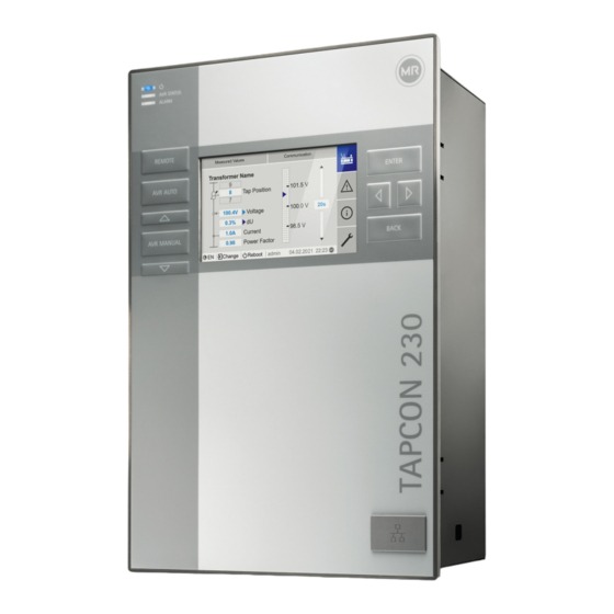
MR TAPCON 230 AVT Operating Instructions Manual
Voltage regulator
Hide thumbs
Also See for TAPCON 230 AVT:
- Supplement manual (20 pages) ,
- Operating instructions manual (166 pages)

Related Manuals for MR TAPCON 230 AVT


Summary of Contents for MR TAPCON 230 AVT
- Page 1 THE POWER BEHIND POWER. Operating instructions ® TAPCON 230 AVT. Voltage regulator 7820299/07 EN...
- Page 2 Generally the information provided and agreements made when processing the individual quotations and orders are binding. The product is delivered in accordance with MR's technical specifications, which are based on information provided by the customer. The customer has a duty of care to ensure the compatibility of the specified product with the customer's planned scope of application.
-
Page 3: Table Of Contents
Table of contents 1 Introduction ..........5 6.4 Connecting device ............. 34 1.1 Manufacturer ..............5 6.4.1 Cable recommendation ........34 1.2 Completeness ............... 5 6.4.2 Electromagnetic compatibility....... 35 1.3 Safekeeping ..............5 6.4.3 Connecting the device grounding to the 1.4 Notation conventions .......... - Page 4 9.3 On-load tap-changer regulator ......... 85 9.3.1 Voltage regulation ........... 85 9.3.2 Parallel operation ..........90 9.3.3 U bandwidth monitoring ........ 97 9.4 On-load tap-changer ..........99 9.4.1 Tap position monitoring ......... 99 9.4.2 Tap position capture method ......99 9.4.3 Target-tap-position operation ......
-
Page 5: Introduction
– Available for download at www.reinhausen.com – Available for download in the MR Customer Portal https://portal.rein- hausen.com 1.3 Safekeeping Keep this technical document and all supporting documents ready at hand and accessible for future use at all times. Download the operating instructions from the device. -
Page 6: Information System
1.4.1.1 Warning relating to section Warnings relating to sections refer to entire chapters or sections, sub-sections or several paragraphs within this technical file. Warnings relating to sections use the following format: WARNING Type of danger! Source of the danger and outcome. Action Action 1.4.1.2 Embedded warning information... -
Page 7: Typographic Conventions
Multi-step instructions Instructions which consist of several process steps are structured as follows: Aim of action Requirements (optional). 1. Step 1. Result of step (optional). 2. Step 2. Result of step (optional). Result of action (optional). 1.4.4 Typographic conventions Typographic convention Purpose Example UPPERCASE... -
Page 8: Safety
2 Safety – Read this technical file through to familiarize yourself with the product. – This technical file is a part of the product. – Read and observe the safety instructions provided in this chapter. – Read and observe the warnings in this technical file in order to avoid func- tion-related dangers. -
Page 9: Fundamental Safety Instructions
2.3 Fundamental safety instructions To prevent accidents, malfunctions and damage as well as unacceptable ad- verse effects on the environment, those responsible for transport, installation, operation, maintenance and disposal of the product or parts of the product must ensure the following: Personal protective equipment Loosely worn or unsuitable clothing increases the danger of becoming trapped or caught up in rotating parts and the danger of getting caught on protruding... -
Page 10: Personnel Qualification
Explosion protection Highly flammable or explosive gases, vapors and dusts can cause serious explo- sions and fire. – Do not install or operate the product in areas where a risk of explosion is present. Safety markings Warning signs and safety information plates are safety markings on the prod- uct. -
Page 11: Personal Protective Equipment
Operator The operator uses and operates the product in line with this technical file. The operating company provides the operator with instruction and training on the specific tasks and the associated potential dangers arising from improper han- dling. Technical Service We strongly recommend having maintenance, repairs and retrofitting carried out by our Technical Service department. -
Page 12: Security
3 IT security Observe the following recommendations to operate the product safely. 3.1 General – Ensure that only authorized personnel have access to the device. – Only use the device within an ESP (electronic security perimeter). Do not con- nect the device to the Internet in an unprotected state. Use mechanisms for vertical and horizontal network segmentation and security gateways (fire- walls) at the transition points. -
Page 13: Communication Interfaces
Default setting; if you have modified the port for the control system protocol, only the set port is open. Port is closed if you activate the device's SSL encryption. SSH is disabled when MR service access is disabled. 7820299/07 EN IT security ... -
Page 14: Product Description
4 Product description 4.1 Function description of the voltage regulation The device keeps the output voltage of a transformer with an on-load tap- changer constant. The device compares the transformer's measured voltage (U ) with a defined actual reference voltage (U ). -
Page 15: Performance Features
Optional – Housing for wall mounting – Device type-dependent: – Ethernet to FO converter (SFP module) – Serial to FO converter 4.3 Performance features – Web-based visualization – Automatic voltage regulation – 1 to 3 desired values – Desired value setting –... -
Page 16: Design
Local mode (LOCAL) In local mode, you can make entries and issue commands using the device's op- erating controls. You cannot use inputs to make entries or issue commands. Remote mode (REMOTE) In remote mode, you can make entries and issue commands using digital in- puts. -
Page 17: Leds
6 Display 7 Front interface RJ45 Ethernet interface 8 ENTER key Confirm selection/save modified parameters 9 LEFT cursor Navigate to the left in the menu 10 RIGHT cursor Navigate to the right in the menu 11 BACK key Exit the current menu. Return to the previ- ous menu level 4.5.2 LEDs Figure 3: LEDs... -
Page 18: Front Interface
4.5.3 Front interface The parameters for the device can be set using a PC on site. The RJ45 Ethernet interface, which can be found under the interface cover, is provided for this pur- pose. To establish a connection with the device, refer to the Visualization sec- tion in the operating instructions. -
Page 19: Connections And Fuses
4.5.4 Connections and fuses The connections are located on the rear of the device. You will find more infor- mation on the connections in the Technical data [►Section 13, Page 113] sec- tion. Figure 5: Rear 1 F2 Internal fuse for the power 2 X9 Power supply supply... -
Page 20: Nameplate
Connections and terminals Figure 6: Connections/terminals 1 COM-X6 CAN bus/SCADA in- 2 COM X5 Interface for patch cable for terface RS485/resis- SCADA via fiber-optic cable tor contact series 3 COM X4 Fiber-optic cable (SFP 4 COM X3 SCADA interface RS232 cage for the SFP mod- ule) 5 COM X2 Interface for visualiza-... -
Page 21: Visualization
4.5.7 Visualization 4.5.7.1 Main screen Home Figure 8: Home 1 Secondary navigation or navigation 2 Primary navigation path 3 Status bar 4 Display area Measured values/display Figure 9: Measured values/display 1 Transformer name (can be edited) 2 Tap position 3 Actual measured values: Voltage, control deviation with correction, cur- rent, power factor 7820299/07 EN Product description ... - Page 22 Desired values/actual values/delay time Figure 10: Desired values/actual values/delay time 1 Desired value 2 Upper limit of bandwidth 3 Mode: Independent mode/parallel op- 4 Trend of corrected voltage (correction eration due to compensation or parallel oper- ation) 5 Delay time T1 6 Lower limit of bandwidth 4.5.7.2 Operating concept You can operate the device using the controls on the front panel or using the...
- Page 23 Navigation If you are operating the device using the operating controls on the front panel, you can use the keys to navigate through the entire menu. The menu currently selected has a blue border. To open the highlighted menu, you have to press the key.
- Page 24 Entering text 1. Use to select the text box and press If operating via the front panel, the keyboard appears. Figure 12: Entering text 2. Enter the desired text and confirm with 3. Press the Accept button to save the modified parameter. Parameter search You can use the quick search function in the parameter menu to search for a parameter.
- Page 25 Expert mode The device has an expert mode for entering the parameters. You can enter the parameters directly on the overview screen of the respective menu in this mode. Figure 14: Expert mode To activate the expert mode, proceed as follows: 1.
-
Page 26: Packaging, Transport And Storage
5 Packaging, transport and storage 5.1 Suitability and structure The goods are packaged in a sturdy cardboard box. This ensures that the ship- ment is secure when in the intended transportation position and that none of its parts touch the loading surface of the means of transport or touch the ground after unloading. -
Page 27: Storage Of Shipments
Visible damage If external transport damage is detected on receipt of the shipment, proceed as follows: – Immediately record the transport damage found in the shipping documents and have this countersigned by the carrier. – In the event of severe damage, total loss or high damage costs, immediately notify the sales department at Maschinenfabrik Reinhausen and the relevant insurance company. -
Page 28: Mounting
6 Mounting DANGER Electric shock! Risk of fatal injury due to electrical voltage. Always observe the following safety regulations when working in or on electrical equipment. Disconnect the equipment. Lock the equipment to prevent an unintentional restart. Make sure all poles are de-energized. Ground and short-circuit. -
Page 29: Assembly Variants
To the base of the control cabinet Minimum clearance: 88.9 mm (3.5 in) Equivalent to 2RU To the roof of the control cabinet Between the device and other assemblies on offset cap rails Table 8: Minimum clearances in the control cabinet 88.9 mm (3.5 in) 88.9 mm (3.5 in) Figure 15: Minimum clearances For other installation types, contact Maschinenfabrik Reinhausen GmbH. - Page 30 1. Cut out the section for the control panel. Figure 17: Cutting out the section for the control panel 2. Push the device into the cutout from the front. Figure 18: Pushing the device into the cutout 3. Insert the tension clamps included in the delivery. Figure 19: Inserting the device into the cutout Mounting 7820299/07 EN...
-
Page 31: Wall Mounting With Housing (Optional)
4. Screw the threaded pins into the tension clamps and secure the device. Figure 20: Securing the device The device is mounted and can be wired up. 6.3.2 Wall mounting with housing (optional) For wall mounting, the device is fixed to the wall in a housing using wall brack- ets. - Page 32 NOTICE! Damage to the housing due to open door. Close the door of the housing to prevent damage during wall mounting. Fix the housing to the wall using 4 screws (M8). Figure 22: Wall mounting The device is mounted and can be wired up. Proceed with wiring as shown in the connection diagram and as described in the “Connecting device”...
- Page 33 2. Insert the tension clamps included in the delivery. Figure 24: Inserting the device into the cutout 3. Screw the threaded pins into the hole in the tension clamp and secure the device. Figure 25: Securing the device The device is mounted and can be wired up. 7820299/07 EN Mounting ...
-
Page 34: Connecting Device
6.4 Connecting device WARNING Electric shock! Connection errors can lead to death, injury or property damage. Ground the device with a protective conductor using the grounding screw on the housing. Note the phase difference of the secondary terminals for the current trans- former and voltage transformer. -
Page 35: Electromagnetic Compatibility
Cable Interface Cable type Conductor cross-section Max. length Power supply (external) Unshielded 1.5 mm² - Voltage measurement UI-X7 Shielded 2.5 mm² - Current measurement UI-X7 Unshielded 2.5 mm² - Digital signal inputs DI 16 Shielded 1.5 mm² 400 m (<25 Ω/km) 8 Digital signal outputs DO 8 Shielded 1.5 mm²... - Page 36 Figure 26: Recommended wiring 1 Cable duct for lines causing interfer- 3 Cable duct for lines susceptible to in- ence terference 2 Line causing interference (e.g. power 4 Line susceptible to interference (e.g. line) signal line) – Short-circuit and ground reserve lines. –...
-
Page 37: Connecting The Device Grounding To The Housing (Optional)
– Line routing in accordance with EMC requirements (separation of lines which cause interference and those susceptible to interference) – Optimum shielding (metal housing) – Overvoltage protection (lightning protection) – Collective grounding (main grounding rail) – Cable bushings in accordance with EMC requirements –... -
Page 38: Connecting Cables To The System Periphery
3. Affix the housing grounding cable to the device grounding screw. If neces- sary, affix the grounding cable protective conductor to the grounding screw as well. Figure 29: Affixing the housing grounding cable and protective conductor to the device 6.4.4 Connecting cables to the system periphery To obtain a better overview when connecting cables, only use as many leads as necessary. - Page 39 Variant 2: The connected devices have different potential levels Note that the shielding is less effective with this variant. Connect the CAN bus cable shielding to just one device. Connect the wires of the shielded CAN bus cable in pins 10 (CAN H), 9 (CAN GND) and 8 (CAN L) of the COM-X6 connector.
-
Page 40: Connecting Scada
6.4.5.2 Mounting terminating resistor of CAN bus If you want to operate the device in parallel operation, you need to mount a 120 Ω terminating resistor at both ends of the CAN bus. Figure 32: Terminating resistor of the CAN bus Mount terminal resistors in pins 10, 9 and 8 of the COM-X6 connector. 6.4.6 Connecting SCADA NOTICE Damage to the device! - Page 41 2. Position the cable shielding, screw it into the shield clamp provided, and pro- vide strain relief (using a cable tie). Figure 34: Shield clamp and strain relief 3. Connect the COM-X1 RJ45 interface and the CPU-X4 interface together us- ing the patch cable. 6.4.6.2 Serial RS232 (D-SUB 9-pole) interface Data cable To connect the device via the RS232 interface, use a data cable with the follow-...
- Page 42 Figure 36: Example of a soldered shielding on a plug housing Connection 1. Connect the D-SUB 9-pole connector to the COM-X3 interface. 2. Connect the COM-X1 RJ45 interface to the CPU-X5 interface using the sup- plied patch cable. 6.4.6.3 Fiber-optic cable To ensure error-free data transmission, observe the information from the man- ufacturer of the fiber-optic cable and the following instructions: –...
- Page 43 2. Remove the SFP module dust plug. Figure 38: Remove the dust protection 3. Insert the fiber-optic cable with LC duplex into the SFP module COM-X4 in- terface. 4. Connect the COM-X5 to the CPU-X2 using the supplied patch cable. Figure 39: Connecting CPU-X5 and COM-X2 Serial fiber-optic cable You will need the CM-0847 FO converter if you want to connect your control system via the serial fiber-optic cable.
-
Page 44: Wiring Voltage Measurement/Current Measurement Ui
6.4.7 Wiring voltage measurement/current measurement UI You must fuse the voltage measurement circuit in accordance with the conduc- tor cross section used. You can use the following fuse types: Miniature circuit breaker Safety fuse Standard IEC 60947-2 IEC 60269 Rated voltage 400 V (L-L) or 230 V (L-N) Rated current 30 mA...16 A Characteristics... -
Page 45: Wiring Analog Inputs Ai
6.4.8 Wiring analog inputs AI NOTICE Damage to the device and sensors! Incorrectly connected and configured analog inputs/outputs may result in damage to the device and sensor. Follow information about connecting analog sensors. Configure analog inputs and outputs according to the connected sensors. You can connect the following types of analog sensors: –... -
Page 46: Wiring Digital Outputs Do
6.4.10 Wiring digital outputs DO CAN bus DO 8 Controller Reinforced insulation 1-pole with 1-pole with connected connected 2-pole positive negative Figure 43: Block diagram for digital outputs 1. Feed the wires into the terminal of the plug connection diagram and fasten them using a screwdriver. - Page 47 6.4.12.2 Connecting to ground 1. Remove the nut and washer from the grounding screw. 2. Attach the grounding cable and the power supply cable grounding wire to the grounding screw of the device and secure them using the nut and washer.
- Page 48 3. Affix the housing grounding cable to the device grounding screw. If neces- sary, affix the grounding cable protective conductor to the grounding screw as well. Figure 46: Affixing the housing grounding cable and protective conductor to the device Mounting 7820299/07 EN...
-
Page 49: Performing Tests
Prior to commissioning, check the supply voltage and the measured volt- age. Connecting the device to mains. The display shows the MR logo and then the operating screen. The voltage display LED on the top left of the device's front panel lights 7820299/07 EN Mounting ... -
Page 50: Initial Steps
7 Initial steps NOTICE Damage to device and system periphery! An incorrectly connected device can cause damage to the device and system periphery. Check the entire configuration before commissioning. As soon as the device has powered up and the start screen is displayed, you will be asked to make the following settings. -
Page 51: Setting The Language
3. Connect the PC and the device via the front interface using an Ethernet cable (RJ45 plug). Figure 48: Establishing a connection via the front interface 4. Assign a unique IP address to the PC in the same subnet as the device (e.g. 192.168.165.100). -
Page 52: Downloading The Operating Instructions
Download the operating instructions from the device to start device commis- sioning and parameterization. Select in the status line. The operating instructions will be downloaded. The document is also available for download in the MR Customer Portal and on our website www.reinhausen.com. Initial steps 7820299/07 EN... -
Page 53: Commissioning
8 Commissioning NOTICE Damage to device and system periphery! An incorrectly connected device can cause damage to the device and system periphery. Check the entire configuration before commissioning. 8.1 Commissioning wizard If you want the device to help when setting the relevant parameters, you can use the commissioning wizard. -
Page 54: Checking Measured Values And Status Of Digital Inputs And Outputs
8.2.1 Checking measured values and status of digital inputs and outputs Upon commissioning the device, check whether the measured values and sta- tus of digital inputs and outputs are plausible. To do so, use an additional mea- suring device if necessary to check the individual measured values. 1. -
Page 55: Checking Parallel Operation
8.2.3 Checking parallel operation To ensure that parallel operation functions correctly, the device must be com- missioned in independent mode. Make sure that the conditions below have been met. – All devices are set to the same operating parameters for "desired value" and "delay time T1"... - Page 56 8.2.3.2 Testing the circulating reactive current blocking limit This section describes how to run the function test for circulating reactive cur- rent blocking. Set the circulating reactive current blocking limit to a value of 20%. 1. Press on one voltage regulator to select manual mode. 2.
- Page 57 3. Compare the tap position displays of master and follower . All de- vices must display the same tap position. If this is not the case, switch all de- vices to the same tap position. Figure 49: Comparing the tap position 1 Master 3 Tap position display 2 Follower...
-
Page 58: Operation
9 Operation 9.1 System 9.1.1 General You can set general parameters in this menu item. 9.1.1.1 Setting general device functions You can set general device functions with the following parameters. Go to Settings > Parameter > System > General. Commissioning wizard You can use this parameter to set whether the commissioning wizard is to launch automatically when the device is restarted. -
Page 59: Setting The Device Time
Go to Settings > Parameter > System > General. Auto logout You can use this parameter to activate th automatic logout function. Time until auto logout You can use this parameter to set the time period of inactivity after which a user is automatically logged out. -
Page 60: Setting The Screensaver
Synchronization interval You can use this parameter to set the interval at which the device is to call up the time from the time server. Time zone If the time information is transmitted to the device by a network service (SNTP or SCADA), this time is transferred depending on the set reference time. -
Page 61: Configuring Syslog
If the screensaver and brightness dimming are activated, you have to press any key twice in order to reactivate the display at full brightness. Dimming waiting time You can use this parameter to set the dimming waiting time. Brightness dimming Setting for the brightness when the display is dimmed. -
Page 62: Scada
Severity level You can set which syslog messages the device will send. You can also activate or deactivate messages for each severity level. Severity level Description The system is unusable. Emergency Immediate intervention required. Alert Critical state Critical Error state Error Warning state Warning... -
Page 63: Linking Signals And Events
Baud rate You can use this parameter to set the serial interface's baud rate. You can select the following options: – 9600 baud – 19200 baud – 38400 baud – 57600 baud – 115200 baud 9.1.6 Linking signals and events The device enables you to link 12 digital inputs (GPI) and control system com- mands (SCADA) with device functions, digital outputs (GPO) and control sys- tem messages. - Page 64 Follower parallel operation method If the assigned event is active, the device activates the follower parallel opera- tion method. Automatic tap synchronization parallel operation method If the assigned event is active, the device activates the automatic tap synchro- nization parallel operation method. Independent regulation If the assigned event is active, the device activates the independent regulation independent mode.
-
Page 65: Configuring Digital Inputs And Outputs
9.1.6.3 Linking status messages You can link each event with a status message. The device provides 10 generic status messages for this purpose. When you link a message to an event, the de- vice sets the data point to "On" when the event occurs. When the event stops, the device sets the data point to "Off". -
Page 66: Event Management
The following information is displayed in tabular form for configuring the digital inputs and outputs. Grayed-out elements cannot be changed. Property Options Function Function of the digital input (I: ...) or the digital output (O: ...). You can adjust the designation. Signal type Select signal type: Digital input Configuration... - Page 67 9.1.8.2 Displaying event memory Past events are stored in the event memory. The following information is dis- played: Column Description Consecutive number of events Event number for clear identification Event category: – Error (red) – Warning (yellow) – Info (gray) Event Event text Time...
-
Page 68: User Administration
9.1.9 User administration User administration is based on a system of roles. You must assign a role to ev- ery user. You can define access rights to parameters and events for each role. 9.1.9.1 Activating/deactivating service user access The device is equipped with user access for the Maschinenfabrik Reinhausen GmbH Technical Service department. - Page 69 Role Description Parameter configurator User who can view and modify data of relevance to operation. – Display and modify all parameters – Import and export parameters – Display, modify, and acknowledge all events Administrator User who can view and modify all data. –...
-
Page 70: Hardware
– Group account: With this option, you can declare a user account to be a group account (e.g. for access by different people). Users with a group ac- count cannot change their own password. The password can only be changed by the administrator. –... -
Page 71: Import/Export Manager
9.1.12 Import/export manager The device is equipped with an import/export manager which can be used to transmit data using a PC via the web-based visualization system. 9.1.12.1 Exporting data You can export the following data from the device: Option Description System image Complete image of the system (software and configuration). - Page 72 NOTICE Damage to the file system! The file system can become damaged due to an incorrect data transmission process. A damaged file system can lead to the device no longer being func- tional. Do not disconnect the device from the power supply during the import. 1.
-
Page 73: Power Grid
9.2 Power grid 9.2.1 Transformer data The transformation ratios and measuring set-up for the voltage and current transformers used in the system can be set with the following parameters. The device uses this information to calculate the corresponding measured values on the primary side of the current transformer (and therefore the transformer) from the recorded measured values. - Page 74 Voltage-transformer circuit You can use this parameter to set your voltage transformer's circuit. You can se- lect the following options: Option Description 1 Ph phase voltage Measurement in 1-phase grid between the conductor and neutral conductor. 3 Ph differential voltage Measurement in 3-phase grid between 2 con- ductors 3 Ph phase voltage...
- Page 75 – The voltage transformer VT is connected to the phase conductor and the neutral conductor. – The current transformer CT is looped into the phase conductor. – The voltage U and current I are in phase. – The voltage drop on a phase conductor is determined by the current I If you use this circuit, set the device as follows: Parameter Option...
- Page 76 – The voltage transformer VT is connected to the phase conductors L1 and L2. – The current transformer CT1 is looped into the phase conductor L1 and CT2 is looped into the phase conductor L2. – The current transformers CT1 and CT2 are connected crosswise in parallel (total current = I + I –...
- Page 77 Circuit 1-E Figure 55: Circuit 1-E – The voltage transformer VT is connected to the phase conductors L1 and L2. – The current transformer CT is looped into the phase conductor L2. – The current I is ahead of voltage U by 30°.
-
Page 78: Voltage Monitoring
9.2.2 Voltage monitoring In order to monitor the transformer's current output voltage, you can set 4 limit values: – Undervoltage U<<: Lower limit 2 – Undervoltage U<: Lower limit 1 – Overvoltage U>: Upper limit 1 – Overvoltage U>>: Upper limit 2 If the measured value is higher than the upper limit (> or >>) or lower than the lower limit (<... -
Page 79: Current Monitoring
Behavior You can use this parameter to set the behavior of the device if the measured value is higher than the upper limit (> or >>) or lower than the lower limit (< or <<). You can select the following options: Setting Behavior No reaction. - Page 80 – I>: Upper limit 1 – I>>: Upper limit 2 If the measured value is higher than the upper limit (> or >>) or lower than the lower limit (< or <<), the device transmits an event message. I>> I> I< I<< Figure 58: Example of current monitoring with the limit value I>...
-
Page 81: Power Monitoring
Reaction You can use this parameter to set the behavior of the device if the measured value is higher than the upper limit (> or >>) or lower than the lower limit (< or <<). You can select the following options: Setting Behavior No reaction. -
Page 82: Power Flow Monitoring
Reaction You can use this parameter to set the behavior of the device if the measured value is higher than the upper limit (> or >>) or lower than the lower limit (< or <<). You can select the following options: Setting Behavior No reaction. -
Page 83: Tapcon® 2Xx Retrofit
Behavior for reversal of power flow You can use this parameter to set the behavior in the event of a reversal of power flow. You can select the following options: Setting Behavior – The negative power flow is ignored. – Automatic regulation remains active. - Page 84 If you activate this parameter, you have to reverse the prefix of the "Phase angle correction" parameter for the transformer data (from - to + or from + to -). Operation 7820299/07 EN...
-
Page 85: On-Load Tap-Changer Regulator
9.3 On-load tap-changer regulator 9.3.1 Voltage regulation All of the parameters required for the control function are described in this sec- tion. Go to Settings > Parameter > Voltage regulator. 9.3.1.1 Setting the desired value You can set three different desired values. The device always uses one of the set desired values for control. - Page 86 9.3.1.1.1 Analog setting of the desired value With the analog setting of the desired value, the desired value for the automatic voltage regulation can be variably adapted using an analog signal (e.g. 4...20 mA). Desired value Max. Min. Min. Max. Analog signal Figure 60: Analog setting of the desired value In order to configure the analog setting of the desired value, you can set the pa-...
- Page 87 Depending on whether positive or negative active power is measured, the de- sired value calculation is based on 2 linear equations (see example in diagram below). Parameter Function Settings (see diagram be- low) : Maximum desired value Maximum set desired value is activated when P is ex- 403.0 V ceeded.
- Page 88 Response to value falling below active power P If the measured active power P falls below the set parameter P , the value meas is adopted as the desired value. Response to a measured active power P = 0 MW: meas If the measured active power P = 0, the set parameter U is adopted.
- Page 89 TDSC Pmax/Pmin You can use these parameters to set the maximum and minimum active power value at which the maximum and minimum active power-dependent desired value is to be used for regulation. 1. Go to Settings > Parameters > Control > TDSC Pmax/Pmin. 2.
-
Page 90: Parallel Operation
is issued after expiration of the set delay time T1. The on-load tap-changer carries out a tap-change in a raise or lower direction to return to the tolerance bandwidth. Figure 62: Behavior of the control function with delay time T1 1 Upper limit of bandwidth 4 Set delay time T1 2 Desired value 5 Control variable measured value... - Page 91 9.3.2.1.1 Tap synchronization With the tap synchronization parallel operation method, one voltage regulator works as the master and all others as followers. Master Follower Tap position CAN bus Figure 63: Tap synchronization The master handles voltage regulation and transmits its current tap positions to all followers via the CAN bus.
- Page 92 Parameter Auto Master Follower Error if no communication present Behavior if no communica- tion present Parallel operation error de- lay time Table 38: Parameter 9.3.2.1.2 Circulating reactive current minimization with CAN bus communica- tion With the circulating reactive current parallel operation method, parallel opera- tion is carried out using the circulating reactive current minimization method.
- Page 93 – Behavior if no communication present – Parallel operation error delay time 9.3.2.1.3 Circulating reactive current minimization without CAN bus communi- cation With this method, you can operate several voltage regulators without a com- munication connection (CAN bus) in parallel with circulating reactive current minimization.
- Page 94 9.3.2.2 Configuring parallel operation In the Parallel operation menu item, you can set the parameters needed for parallel transformer operation. Go to Settings > Parameter > Voltage regulator > Parallel operation. 9.3.2.2.1 Activating parallel operation You can use this parameter to activate or deactivate parallel operation. 9.3.2.2.2 Setting parallel operation method You can use this parameter to set the parallel operation method.
- Page 95 ceeds the set limit value, the device triggers the Circulating reactive current blocking limit exceeded event. All devices operating in the parallel operation group are blocked. Desired power factor You can use this parameter to set the power factor, which the transformer has under normal operating conditions.
- Page 96 If the tap difference is greater than the set maximum tap difference to the mas- ter, the follower blocks and no longer attempts to attain the master's tap posi- tion. After the set delay time for parallel operation error messages has elapsed, the follower issues the Permitted tap difference to master exceeded message.
-
Page 97: U Bandwidth Monitoring
Description Active current Reactive current Block. Blocking: – Gray: Parallel operation not blocked – Red: Parallel operation blocked Table 41: Information about parallel operation Go to Information> Parallel operation. 9.3.3 U bandwidth monitoring The following limit values are monitored via bandwidth monitoring. The set bandwidth [►Page 89] (upper/lower) of the voltage regulation is used for this purpose. - Page 98 Delay time You can use this parameter to set the delay time in order to delay the issuing of the event message. Operation 7820299/07 EN...
-
Page 99: On-Load Tap-Changer
9.4 On-load tap-changer 9.4.1 Tap position monitoring You can set the limit value parameter for tap position monitoring: Go to Settings > Parameter > Voltage regulation > Tap position monitoring. Delay time You can use this parameter to set the delay time in order to delay the issuing of the event message. - Page 100 The tap position is transmitted in one of the following ways: 9.4.2.1 Digital tap position capture The tap position can be transmitted as a digital signal from the motor-drive unit to the device. The following variants are available: – – Dual code –...
-
Page 101: Target-Tap-Position Operation
12. Step 3: Manually switch the on-load tap-changer to the lowest tap position. ð Step 4: The device determines the offset and once complete moves on to step 5. 13. Step 5: Press the Next button to complete calibration. Calibration of tap position capture using the resistor contact series has been performed successfully. -
Page 102: Motor-Drive Unit And Control Cabinet
9.5 Motor-drive unit and control cabinet 9.5.1 Control of the motor-drive unit 9.5.1.1 Setting the switching pulse for controlling the motor-drive unit You can use the parameters Switching pulse type, Switching pulse time and Switching pulse pause to adapt the device switching pulse to the requirements of the motor-drive unit controller. - Page 103 Switching pulse time You can use this parameter to set the maximum duration of the switching pulse. The switching pulse resets after the switching pulse time has elapsed or if the device receives the Motor running signal beforehand or the tap position is changed.
- Page 104 U switching direction You can use this parameter to set the switching direction for voltage regulation. You can use this to adjust the behavior of the device based on how your on- load tap-changer and motor-drive unit are configured. You can select the fol- lowing options: Setting Meaning...
-
Page 105: Maintenance And Care
7. Select the device in the Firmware tab and select the Create firmware button in the MR Versions entry for the desired version. If the firmware cannot be generated automatically, you will see the Request button, which you can use to send a request to Maschinenfabrik Reinhausen GmbH. -
Page 106: Establishing Connection To Visualization
Depending on your operating system, you can calculate the hash value of the file in different ways. If you run your PC with Windows 10, you can cal- culate the hash value in the command line with the following command: certutil –hashfile <filename>.zip sha256 11. -
Page 107: Updating Application Software
4. Assign a unique IP address to the PC in the same subnet as the device (e.g. 192.168.165.100). 5. Enter the visualization's IP address http://192.168.165.1, or if SSL en- cryption is active, enter https://192.168.165.1 in the browser on the The visualization is accessed. Establishing a connection via the rear CPU-X3 interface 1. -
Page 108: Fault Elimination
11 Fault elimination 11.1 General faults Characteristics/details Cause Remedy No function No power supply. Check the power supply. – Power supply LED does not light Fuse tripped. Contact Maschinenfabrik Reinhausen GmbH. No function Configuration error Contact Maschinenfabrik Reinhausen GmbH. – AVR STATUS LED does not light Relay chatter High EMC load. -
Page 109: Human-Machine Interface
Characteristics/details Cause Remedy Parallel operation active. Device is follower in parallel opera- No error. If necessary, deactivate parallel operation. tion. CAN bus communication failure "Auto blocking" behavior is set. Check configuration. Table 45: No regulation in AUTO mode 11.3 Human-machine interface Characteristics/details Cause Remedy... -
Page 110: Parallel Operation Faults
Characteristics/details Cause Remedy Measured current Line to the current transformer inter- Check wiring. – No measured value rupted. Short-circuiting jumper in current Remove the short-circuiting jumper. transformer is not removed. Measured current Current transformer not correctly Correct parameterization. – Measured value too high parameterized. -
Page 111: Tap Position Capture Incorrect
11.6 Tap position capture incorrect Characteristics/details Cause Remedy Position indicator incorrect. Incorrect wiring. Check wiring. – Leading sign incorrect. Connect as shown in the connection diagram. Minimum value of the analog input Check parameters. signal not configured correctly. Position indicator incorrect. Interference. -
Page 112: Disposal
12 Disposal Observe the national requirements applicable in the country of use. Disposal 7820299/07 EN... -
Page 113: Technical Data
13 Technical data 13.1 Display elements Display 5″ TFT colour display LEDs 3 LEDs for operation display and messages – POWER, AVR STATUS, ALARM – RAISE, LOWER, AUTO, MANUAL, REMOTE 13.2 Materials TAPCON® 230 Front Aluminum, plastic Tray/rear Stainless steel Housing (optional) Plastic 13.3 Dimensions TAPCON® 230... -
Page 114: Voltage Measurement And Current Measurement
Interface Description Table 51: Connection X9 Auxiliary power supply AUX DC DI 110 V DC for digital inputs The auxiliary power supply is used exclusively for the acquisition of up to 16 floating contacts. Output voltage : 110 V DC ± 2% (short-circuit proof) Max. output power 5 W Overvoltage category OC III... -
Page 115: Central Processing Unit
Current measurement Frequency 45…65 Hz Nominal current I 1 A or 5 A (switchable) Accuracy < ±0.5% x I in the operating temperature range Load resistance < 0.1 VA Overload capability continuous 20 A (IEC 60255-27) Overload capacity short-term 500 A / 1 s Surge test voltage 5 kV, 1.2 µs / 50 µs (IEC 60255-27) Interface Description VT (U : 100/230/400 V AC) Table 54: Connection UI:X7... - Page 116 Interfaces Interface Description ER_NO ER_NC ER_COM WD_NO WD_NC WD_COM Table 55: Plug terminal CPU:X1 Interface X2, X3 Description RXD- RXD+ TXD- TXD+ Table 56: Ethernet interface CPU:X2/X3 Interface X4 Description TXD+/RXD+ TXD-/RXD- Table 57: Serial interface RS485 CPU:X4 Interface X5 Description DTR (O) DCD (I) RXD (I) TXD (O)
-
Page 117: Digital Inputs
13.7 Digital inputs DI 16-110V Inputs (plug-based electrical 2 x 8 isolation) Nominal voltage 110 VDC Max. operating voltage 143 VDC Logical 0 ≤ 55 VDC Logical 1 ≥ 82.5 VDC Input current 0.9 mA Simultaneity factor Max. 13 inputs (at 65°C ambient temperature) Table 59: DI 16-110V technical data Interface Description Common reference (common) -
Page 118: Digital Outputs
13.8 Digital outputs DO 8 Outputs (plug-based electrical isolation) 8 relays 4 groups per module Switching voltage DC: 24 V, 48 V, 60 V, 110 V, 220 V AC: 110 V, 230 V Contact load capacity Min.: 5 V DC, 10 mA Max. DC: See diagram Max. AC: 250 V; 3 A (8 active outputs) or 5 A (4 active outputs) Table 62: DO 8 assembly technical data Ohmic load... -
Page 119: Analog Inputs
Interface Description Common reference (common) output 3 Common reference (common) output 2 Output 3 Output 2 Table 64: Connector X2 (group 1) Interface Description Common reference (common) output 5 Common reference (common) output 4 Output 5 Output 4 Table 65: Connector X3 (group 2) Interface Description Common reference (common) output 7... -
Page 120: Communication Interfaces
Interface Description V0 U- voltage input V0 I- current input V0 I+ current output V0 U+ voltage output Table 68: Connector X1 (group 0) Interface Description V1 U- voltage input V1 I- current input V1 I+ current output V1 U+ voltage output Table 69: Connector X2 (group 1) Interface Description V2 U- voltage input V2 I- current input V2 I+ current output... - Page 121 COM X3 Serial SCADA interface RS232 – 9-pin D-SUB connector COM X4 SFP module for converting Ethernet (RJ45) to fiber- optic cable for SCADA – Max. 2,000 m – 100 Mbps – Light-emitting diode: class 1 – Wave length: 1,310 nm – Max. optical output power: <1 mW (in accor- dance with IEC 60825-1:2014) COM X5 Ethernet connection for SCADA, connection to...
-
Page 122: Tap Position Capture / Resistor Contact Series
Interface Description Table 74: COM X3 (RS232) Interface Description Fiber glass 50/125 and 62.5/125 multimode Table 75: COM X4 (duplex LC SFP) Interface Description GND (resistor contact series) I out (resistor contact series) U+ in (resistor contact series) U- in (resistor contact series) Data- (RS485) GND (RS485) Data+ (RS485) -
Page 123: Standards And Directives
Degree of protection Front: IP54 Rear: IP20 With optional housing: IP56 Maximum installation alti- 3000 m above mean sea level tude Minimum clearance to other Above/below: 88.9 mm (3.5 in; equivalent to 2 RU), behind devices / control cabinet 30 mm (1.2 in) Table 77: Permissible ambient conditions 13.13 Standards and directives Electromagnetic compatibility IEC 61000-6-2, IEC 61000-6-4,... -
Page 124: Connection Diagrams
13.14 Connection diagrams Also refer to 2 TAPCON® 230 AVT [► 125] Technical data 7820299/07 EN... -
Page 125: Tapcon® 230 Avt
TAPCON® 230 - AVT CENTRAL PROCESSING UNIT POWER SUPPLY DIGITAL OUTPUTS DO 8-1 DIGITAL INPUTS DI 16-110V AC/DC N (L-) L1 (L+) 110V DC LANGUAGE: PROJECT: DATE 22.01.2021 X7,X1,X6 connection 01.10.21 LAINER EXEC. BECK TAPCON® 230 AVT BCD SIGNAL 30.06.21 KAHN VERIFIED SHEET... - Page 126 TAPCON® 230 - AVT CENTRAL PROCESSING UNIT DIGITAL OUTPUTS DO 8-2 ANALOG INPUTS AI 4 COM - 120 Ω (II) 100% TAP POSITION POSITION TRANSMITTER MODULE, RESISTOR-TYPE (III) Ω LANGUAGE: PROJECT: DATE 22.01.2021 X7,X1,X6 connection 01.10.21 LAINER EXEC. BECK TAPCON® 230 AVT BCD SIGNAL 30.06.21 KAHN...
- Page 127 CUSTOMER VISU / SERVICE RJ45 RJ45 RJ45 RJ45 SCADA ETHERNET LC 1310nm RJ45 RJ45 RJ45 SCADA SERIAL SIGNAL RS232 RJ45 SIGNAL Data - RS485 Data + RJ45 LANGUAGE: PROJECT: DATE 22.01.2021 X7,X1,X6 connection 01.10.21 LAINER EXEC. BECK TAPCON® 230 AVT BCD SIGNAL 30.06.21 KAHN...
-
Page 128: Glossary
Glossary Electromagnetic compatibility General Purpose Input General Purpose Output Abbreviation for fiber-optic cable SCADA Technical processes are monitored and controlled using a computer system (Supervisory Control and Data Acqui- sition) SNTP NTP (Network Time Protocol) is a standard for synchro- nizing clocks in computer systems using packet-based communication networks. - Page 130 Maschinenfabrik Reinhausen GmbH Falkensteinstrasse 8 93059 Regensburg Germany +49 941 4090-0 info@reinhausen.com reinhausen.com Please note: The data in our publications may differ from the data of the devices delivered. We reserve the right to make changes without notice. ® 7820299/07 EN - TAPCON 230 AVT Operating instructions - 01/24 THE POWER BEHIND POWER.
Need help?
Do you have a question about the TAPCON 230 AVT and is the answer not in the manual?
Questions and answers