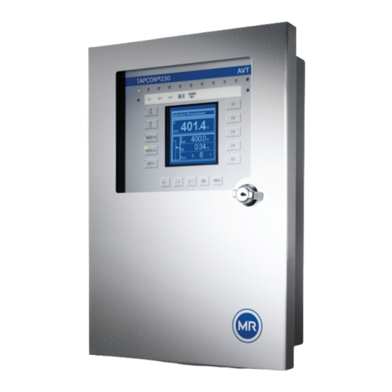
MR TAPCON 230 AVT Supplement Manual
Voltage regulator. device profile document modbus
Hide thumbs
Also See for TAPCON 230 AVT:
- Operating instructions manual (166 pages) ,
- Operating instructions manual (130 pages)
Summary of Contents for MR TAPCON 230 AVT
- Page 1 ® ® Laststufenschalter VACUTAP Voltage Regulator TAPCON 230 AVT VR I HD Betriebsanleitung Supplement Device Profile Document MODBUS...
- Page 2 © Alle Rechte bei Maschinenfabrik Reinhausen Weitergabe sowie Vervielfältigung dieses Dokumentes, Verwertung und Mitteilung seines Inhalts sind verboten, soweit nicht ausdrücklich gestattet. Zuwiderhandlungen verpflichten zu Schadenersatz. Alle Rechte für den Fall der Patent-, Gebrauchsmuster- und Geschmacksmustereintragung vorbehalten. Nach Redaktionsschluss der vorliegenden Dokumentation können sich am Produkt Änderungen ergeben haben. Änderungen der technischen Daten bzw.
-
Page 3: Table Of Contents
Table of Contents General ..................5 Introduction ....................5 Abbreviations used ...................5 Communication Interface Ports ..........7 Settings on the voltage regulator ..............8 2.1.1 RS-232 ......................... 8 2.1.2 RS-485 ......................... 9 2.1.3 Ethernet (RJ45) ....................9 2.1.4 Optical Fiber ....................... 10 Protocol specification .............. -
Page 5: General
General Introduction This implementation of the MODBUS® communication protocol (ASCII and ® RTU mode) in the TAPCON 230 AVT is based on the Modicon MODBUS Pro- tocol Reference Guide, PI-MBUS-300 Rev. J, copyright 1996 by Modicon Inc. ® This document details the implementation subset available in a TAPCON AVT voltage controller equipped with the optional communication interface module (CI-module). -
Page 7: Communication Interface Ports
Communication Interface Ports Ethernet Optical Fiber RS 485 RS 232 Figure 1 Communication Interface Ports For data transfer via MODBUS protocol the voltage regulator provides the foll- wing communication interface ports: 9 pin female SUB-D connector Pin 2: TxD RS-232 Pin 3: RxD Pin 5: GND 3 pin male connector from Phönix MSTB 2,5/3-GF-5... -
Page 8: Settings On The Voltage Regulator
Settings on the voltage regulator Getting started with MODBUS communication some parameters must be set on ® the TAPCON 230 AVT. MENU-key > Configuration > Continue > Continue > Comm. Interface For further instructions on setting the configuration parameters please refer to ®... -
Page 9: Ethernet (Rj45)
2.1.2 RS-485 Communication protocol MODBUS ASCII or MODBUS RTU Communication port RS-485 Communication baud rate 9600/19200/38400/57600 Baud IP address Not used TCP port Not used Light On/Off Mode Not used Local SCADA address 1..255 (0 = broadcast) SCADA master address Not used for MODBUS Unsolicited messages Not used for MODBUS... -
Page 10: Optical Fiber
2.1.4 Optical Fiber Communication protocol MODBUS ASCII or MODBUS RTU Communication port Optical Fiber Communication baud rate 9600/19200/38400/57600 Baud IP address Not used TCP port Not used Light On/Off Mode ON means light ON at 1 OFF means light OFF at 1 Local SCADA address 1..255 (0 = broadcast) SCADA master address... -
Page 11: Protocol Specification
Protocol specification Modbus ASCII: 7-E-1 (7 data bits, even parity, 1 stop bit) Modbus RTU:8-E-1 (8 data bits, even parity, 1 stop bit) Function codes Following function codes are supported: Funciton Code Name Read coil status Read input status Read holding registers Read input registers Force single coil Preset single register... -
Page 12: Modbus Adressing Model
General notes: Multiple communication links are not supported. Communication is half-duplex mode. Addresses in this document refers to the MODBUS PDU addresses. Example: Reading input status with address 8 will read address 7 in the Discrete Input block of the MODBUS data model. MODBUS adressing model MODBUS data model MODBUS PDU addresses... -
Page 13: Device Data Points
Device Data Points Coils Point Name for Name for Adre Name State when State when Description value is 0 value is 1 Selection of Desired Voltage Level 1 (only possible if there is no GPI set to an VL) Desired Voltage Select VL 1 Pulse/Latch On/Off times are fixed hard- Level 1... - Page 14 Point Name for Name for Adre Name State when State when Description value is 0 value is 1 Master method selection (only possible if Select Master there is no GPI set to Master/Follower) Parallel Master Paralleling Pulse/Latch On/Off times are fixed hard- Method ware dependent.
-
Page 15: Input Status
Input Status Point Name for Name for Adre Name State when State when Description value is 0 value is 1 Desired Voltage VL 1 inactive VL 1 active Activation status of Desired Voltage Level 1 Level 1 Desired Voltage VL 2 inactive VL 2 active Activation status of Desired Voltage Level 2 Level 2... - Page 16 Point Name for Name for Adre Name State when State when Description value is 0 value is 1 Overvoltage No overvoltage Overvoltage Overvoltage detection status No undervol- Undervoltage Undervoltage Undervoltage detection status tage Overcurrent No overcurrent Overcurrent Overcurrent detection status No undercur- Undercurrent Undercurrent Undercurrent detection status...
- Page 17 Point Name for Name for Adre Name State when State when Description value is 0 value is 1 GPI 7 Input GPI 7 inactive GPI 7 active Status of General Purpose Input 7 GPI 8 Input GPI 8 inactive GPI 8 active Status of General Purpose Input 8 Position Bit 0 Position Bit 0...
-
Page 18: Holding Registers
Holding Registers Transmitted Value Scaling Point Reso- Name Units Description Mini- Maxi- Multi- Adress lution Offset plier Desired Voltage 2200 4400 Level 1 Desired Voltage 2200 4400 Level 2 Desired Voltage 2200 4400 Level 3 reserved 65535 reserved 65535 reserved 65535 reserved 65535... -
Page 19: Input Registers
Input Registers Transmitted Value Scaling Point Reso- Name Units Description Mini- Maxi- Multi- Adress lution Offset plier Desired Voltage 2200 4400 Level 1 Desired Voltage 2200 4400 Level 2 Desired Voltage 2200 4400 Level 3 Operation The value of Operation Counter 99999999 Counter consists of... - Page 20 2224208/00 EN • 02/10 • F0223000...


Need help?
Do you have a question about the TAPCON 230 AVT and is the answer not in the manual?
Questions and answers