MR tapcon 230 pro Operating Instructions Manual
Voltage regulator
Hide thumbs
Also See for tapcon 230 pro:
- Operating instructions manual (150 pages) ,
- Operating instructions manual (166 pages)
Table of Contents
Advertisement
Advertisement
Table of Contents

Related Manuals for MR tapcon 230 pro


Summary of Contents for MR tapcon 230 pro
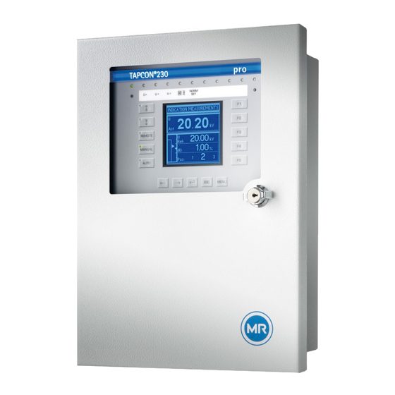
- Page 1 Voltage Regulator TAPCON® 230 pro Operating Instructions 3550953/00 EN...
- Page 2 © All rights reserved by Maschinenfabrik Reinhausen Dissemination and reproduction of this document and use and disclosure of its content are strictly prohibited unless expressly permitted. Infringements will result in liability for compensation. All rights reserved in the event of the granting of patents, utility models or designs.
-
Page 3: Table Of Contents
Table of contents Table of contents Introduction ......................... 8 Manufacturer ............................8 Subject to change without notice ......................8 Completeness............................8 Safekeeping............................8 Notation conventions ........................... 8 1.5.1 Hazard communication system ..........................9 1.5.2 Information system .............................. 10 1.5.3 Instruction system ............................... 10 1.5.4 Typographic conventions ............................ - Page 4 Table of contents Transportation, receipt and handling of shipments................27 Storage of shipments......................... 28 Mounting ..........................30 Preparation ............................30 Mounting device ..........................30 5.2.1 Flush panel mounting ............................32 5.2.2 Wall mounting with mounting brackets ........................ 33 5.2.3 Cap rail mounting ..............................34 5.2.4 Wall mounting..............................
- Page 5 Table of contents 7.2.6 Activating/deactivating the automatic key lock ....................63 7.2.7 "Function monitoring" message for monitoring messages <30 V................ 64 7.2.8 Setting motor runtime monitoring ........................65 7.2.9 Activate manual mode/auto mode ........................67 7.2.10 Activating Local/Remote............................67 NORMset ............................68 Control parameters ..........................
- Page 6 Table of contents 7.8.8 Activating/deactivating parallel operation ......................105 Tap position capture ........................106 7.9.1 Digital tap position capture ..........................106 7.9.2 Analog tap position capture..........................107 7.10 Setting the desired voltage level remotely..................109 7.10.1 Activate/deactivate setting the desired voltage level remotely................110 7.10.2 Setting lower limit value for the desired value ....................
- Page 7 Table of contents Messages ......................... 131 Disposal ........................... 134 Overview of parameters ....................135 Technical data ......................... 139 12.1 Display elements ..........................139 12.2 Electrical data ..........................139 12.3 Dimensions and weight ........................139 12.4 Ambient conditions .......................... 141 12.5 Electrical safety ..........................
-
Page 8: Introduction
1 Introduction Introduction This technical file contains detailed descriptions on the safe and proper in- stallation, connection, commissioning and monitoring of the product. It also includes safety instructions and general information about the prod- uct. This technical file is intended solely for specially trained and authorized per- sonnel. -
Page 9: Hazard Communication System
1 Introduction 1.5.1 Hazard communication system Warnings in this technical file are displayed as follows. 1.5.1.1 Warning relating to section Warnings relating to sections refer to entire chapters or sections, sub-sec- tions or several paragraphs within this technical file. Warnings relating to sections use the following format: Type and source of danger WARNING... -
Page 10: Information System
1 Introduction Pictogram Meaning Warning of dangerous electrical voltage Warning of combustible substances Warning of danger of tipping Table 2: Pictograms used in warning notices 1.5.2 Information system Information is designed to simplify and improve understanding of particular procedures. In this technical file it is laid out as follows: Important information. -
Page 11: Typographic Conventions
1 Introduction Step 1. ð Result of step (optional). Step 2. ð Result of step (optional). ð Result of action (optional). 1.5.4 Typographic conventions The following typographic conventions are used in this technical file: Typographic Purpose Example convention UPPERCASE Operating controls, ON/OFF switches [Brackets]... -
Page 12: Safety
2 Safety Safety General safety information The technical file contains detailed descriptions on the safe and proper in- stallation, connection, commissioning and monitoring of the product. ▪ Read this technical file through carefully to familiarize yourself with the product. ▪ Particular attention should be paid to the information given in this chap- ter. -
Page 13: Personnel Qualification
2 Safety Personnel qualification The product is designed solely for use in electrical energy systems and facili- ties operated by appropriately trained staff. This staff comprises people who are familiar with the installation, assembly, commissioning and operation of such products. Operator's duty of care To prevent accidents, disruptions and damage as well as unacceptable ad- verse effects on the environment, those responsible for transport, installa-... -
Page 14: Product Description
Voltage regulator TAPCON® 230 ▪ Folder with all device documentation ▪ Quick reference guide (in the inside door of the device) ▪ MR-Suite CD (contains the TAPCON®-trol program) ▪ Door key ▪ 3mm Allen key ▪ 2 countersunk head screws ▪... -
Page 15: Function Description Of The Voltage Regulation
3 Product description Figure 4: Cap rail clip Please note the following: ▪ Check the shipment for completeness on the basis of the shipping docu- ments. ▪ Store the parts in a dry place until installation. Function description of the voltage regulation The TAPCON®... -
Page 16: Performance Features
3 Product description Summer Winter Regulation section Regulating transformer Load profile of grid Automatic voltage regulator TAPCON® 230 Measurement Control variable for line voltage transformer Inputs digital and analog Automatic voltage regulator TAPCON® 230 Station control system for example for parallel operation of up to 16 transformers Remote communication and control room Figure 5: Overview of voltage regulation Performance features... -
Page 17: Operating Modes
3 Product description ▪ Digital inputs and outputs can be individually programmed on-site by the user ▪ Additional indicators using LEDs outside the display for freely selectable functions ▪ Display of all measured values such as voltage, current, active power, apparent power or reactive power, power factor (cos φ) ▪... - Page 18 3 Product description + LOCAL + RE- + LOCAL + RE- MOTE MOTE Automatic regulation Tap-change operation using oper- ating controls Tap-change operation using in- puts Table 4: Overview of operating modes TAPCON® 230 pro 3550953/00 EN Maschinenfabrik Reinhausen 2014...
-
Page 19: Hardware
3 Product description Hardware Figure 6: Hardware Operating panel with display Door and LEDs Door lock Metric cable glands Maschinenfabrik Reinhausen 2014 3550953/00 EN TAPCON® 230 pro... -
Page 20: Name Plate
3 Product description 3.5.1 Name plate The name plate is on the outside of the device: Figure 7: Name plate 3.5.2 Operating controls The device has 15 pushbuttons. The illustration below is an overview of all the device's operating controls . TAPCON®... - Page 21 3 Product description Figure 8: Operating controls RAISE key: Sends control command for raise tap-change to the motor-drive unit in manual mode. LOWER key: Sends control command for lower tap-change to the motor-drive unit in manual mode. REMOTE key: Activate/deactivate "Remote" operating mode. When you deactivate this operating mode, the "Local"...
-
Page 22: Display Elements
3 Product description 3.5.3 Display elements The device has a graphics display and 15 LEDs , which indicate the various operating statuses or events. Figure 9: Indicator elements Operating status LED, green LED 3, function can be freely assigned, yellow/green Overcurrent blocking LED, red LED 4, function can be freely assigned, yellow/red... - Page 23 3 Product description Display Figure 10: Display Status line Bandwidth (upper and lower limit) Measured voltage U Time bar for delay time T1 Reference voltage U Highlighting for measured voltage U Other measured values (use Highlighting for reference volt- age U to switch between them) Tap position n-1;...
-
Page 24: Serial Interface
3 Product description Unit Measured value Active factor: Cosine φ [phi] (output factor) Table 5: Measured value display Status line Current messages and events are displayed in the status line . You can find more information about messages and events in the Messages chapter. 3.5.4 Serial interface The parameters for the device can be set using a PC. - Page 25 3 Product description 3.5.5.1 MIO card Figure 12: MIO card Relay outputs (terminal X4) Current transformer connec- tion (terminal X1) Signal inputs (terminal X4) Voltage transformer connec- tion and network connection (terminal X2) Relay outputs (terminal X3) CAN bus connection Maschinenfabrik Reinhausen 2014 3550953/00 EN TAPCON®...
- Page 26 3 Product description 3.5.5.2 PIO card Figure 13: PIO card Signal inputs and auxiliary Relay outputs (terminal X5) voltage generation (terminal Analog input (terminal X7) Relay outputs (terminal X5) Digital tap position inputs (ter- minal X6) TAPCON® 230 pro 3550953/00 EN Maschinenfabrik Reinhausen 2014...
-
Page 27: Packaging, Transport And Storage
4 Packaging, transport and storage Packaging, transport and storage Packaging 4.1.1 Purpose The packaging is designed to protect the packaged goods during transport, loading and unloading as well as periods of storage in such a way that no (detrimental) changes occur. The packaging must protect the goods against permitted transport stresses such as vibration, knocks and moisture (rain, snow, condensation). -
Page 28: Storage Of Shipments
4 Packaging, transport and storage If a crate tips over, falls from a certain height (e.g. when slings tear) or expe- riences an unbroken fall, damage must be expected regardless of the weight. Every delivered shipment must be checked for the following by the recipient before acceptance (acknowledgment of receipt): ▪... - Page 29 4 Packaging, transport and storage ▪ Store the crates on timber beams and planks as a protection against ris- ing damp and for better ventilation. ▪ Ensure sufficient carrying capacity of the ground. ▪ Keep entrance paths free. ▪ Check stored goods at regular intervals. Also take appropriate action af- ter storms, heavy rain or snow and so on.
-
Page 30: Mounting
5 Mounting Mounting This chapter describes how to correctly mount and connect the device. Note the connection diagrams provided. Electric shock WARNING Risk of fatal injury due to electrical voltage. ► De-energize the device and system peripherals and lock them to pre- vent them from being switched back on. - Page 31 5 Mounting Preparing for mounting Before commencing mounting, the two mounting brackets back on the rear of the device must be removed and the cable gland plate taken off. To do so, proceed as follows: Loosen the 4 Allen screws with attached Allen key to remove the mount- ing brackets.
-
Page 32: Flush Panel Mounting
5 Mounting 5.2.1 Flush panel mounting For flush panel mounting , the device is inserted through a cutout in the con- trol panel and fixed to the control panel or control cabinet from behind using the mounting brackets. The diagram below shows the dimensions required for the control panel cutout. -
Page 33: Wall Mounting With Mounting Brackets
5 Mounting Figure 17: Flush panel mounting ð The device is mounted and can be wired up Proceed with wiring as shown in the connection diagram and as described in the Connecting device [► 37] section. 5.2.2 Wall mounting with mounting brackets As an alternative to mounting the device directly on the wall, it can be fixed to the wall using the mounting brackets supplied. -
Page 34: Cap Rail Mounting
5 Mounting The screws for fixing to the wall are not included in the scope of supply. The screw length required depends on the wall thickness. Figure 19: Wall mounting with mounting brackets ð The device is mounted and can be wired up Proceed with wiring as shown in the connection diagram and as described in the Connecting device [►... -
Page 35: Wall Mounting
5 Mounting Figure 20: Cap rail mounting ð The device is mounted and can be wired up Proceed with wiring as shown in the connection diagram and as described in the Connecting device [► 37] section. 5.2.4 Wall mounting For wall mounting, , the device is fixed directly to the wall. Drill 4 holes, each 5.5 mm in diameter, in the wall as shown in the drilling template below. -
Page 36: Removing The Door
5 Mounting Figure 22: Wall mounting ð The device is mounted and can be wired up Proceed with wiring as shown in the connection diagram and as described in the Connecting device section. 5.2.5 Removing the door When the door is fitted, the device satisfies protection category IP54. The door may be removed if the device is used solely in a dry atmosphere pro- tected from environmental influences. -
Page 37: Connecting Device
5 Mounting Unscrew the fixing bolt using a slotted screwdriver and lift the door out of the upper mounting Figure 24: Lift door from the suspension mount Hook the cover strip in the upper and lower suspension mount and fasten it with the provided raised countersunk head screws. Figure 25: Fasten covering strip ð... -
Page 38: Cable Recommendation
5 Mounting 5.3.1 Cable recommendation Please note the following recommendation from Maschinenfabrik Reinhau- sen when wiring the device. Excessive electrical power can prevent the relay contacts from breaking the contact current. In control circuits operated with alternating current, take into account the effect of the line capacitance of long control lines on the func- tion of the relay contacts. -
Page 39: Electromagnetic Compatibility
5 Mounting Please note the following: ▪ Radii must not fall below the minimum permissible bend radii (do not bend fiber-optic cable). ▪ The fiber-optic cables must not be over-stretched or crushed. Observe the permissible load values. ▪ The fiber-optic cables must not be twisted. ▪... - Page 40 5 Mounting Figure 26: Recommended wiring Cable duct for lines causing Cable duct for lines suscepti- interference ble to interference Interference-causing line (e.g. Line susceptible to interfer- power line) ence (e.g. signal line) ▪ Short-circuit and ground reserve lines. ▪ The device must never be connected using multi-pin collective cables.
- Page 41 5 Mounting Figure 27: Recommended connection of the shielding Connection of the shielding Shielding connection covering using a "pigtail" all areas 5.3.3.3 Wiring requirement in control cabinet Note the following when wiring the control cabinet: ▪ The control cabinet for fitting the device must be prepared in accord- ance with EMC requirements: –...
- Page 42 5 Mounting Figure 28: Ground strap connection Ground connection for wiring inside the device The diagram below shows the ground connection for wiring inside the de- vice. Figure 29: Grounding inside the device 5.3.3.4 Information about shielding the CAN bus In order for the CAN bus to operate faultlessly, you have to connect the shielding using one of the following variants.
- Page 43 5 Mounting NOTICE Damage to the device If the CAN bus cable's shielding is connected to devices with different po- tential, current may flow over the shielding. This current may damage the communication cards. ► Connect the devices to a potential compensation rail to compensate for potential ►...
-
Page 44: Connecting Cables To The System Periphery
5 Mounting 5.3.4 Connecting cables to the system periphery To obtain a better overview when connecting cables, only use as many leads as necessary. To connect cables to the system periphery, proceed as follows: ü Use only the specified cables for wiring. Note the cable recommendation [►... -
Page 45: Wiring Device
5 Mounting 5.3.6 Wiring device To obtain a better overview when connecting cables, only use as many leads as necessary. To wire the device, proceed as follows: ü Use only the specified cables for wiring. Note the cable recommendation [► 38]. - Page 46 5 Mounting Check the following: ▪ Once you have connected the device to the grid, the screen displays the MR logo and then the operating screen. ▪ The green Operating display LED top left on the device's front panel lights up.
-
Page 47: Commissioning
6 Commissioning Commissioning You need to set several parameters and perform function tests before com- missioning the device. These are described in the following sections. NOTICE Damage to device and system periphery An incorrectly connected device can lead to damages in the device and sys- tem periphery. -
Page 48: Setting The Language
6 Commissioning 6.2.1 Setting the language You can use this parameter to set the display language for the device. The following languages are available: English Italian German Portuguese French Russian Spanish To set the language, proceed as follows: > Configuration > General. -
Page 49: Function Tests
6 Commissioning Setting line drop compensation (optional) If you need line drop compensation, you must set all important parameters for this: Select LDC compensation method [► 86]. Set line data for the ohmic voltage drop Ur [► 88]. Set line data for the inductive voltage drop Ux [►... -
Page 50: Checking Control Functions
6 Commissioning ▪ During the function test, you must set the most important parameters. Details on the parameters listed can be found in the Functions and set- tings [► 59] chapter. 6.3.1 Checking control functions This section describes how you can check the device's control functions: ü... -
Page 51: Checking Additional Functions
6 Commissioning 19. Press to select auto mode. ð After 20 seconds, the device lowers the on-load tap-changer one step and after another 10 seconds another step. 20. Press to select manual mode. 21. Set delay time T1 [► 75] and delay time T2 [►... - Page 52 6 Commissioning Reset the operating values for desired value 1 and undervoltage U< [%] to the desired operating values. ð The function test for undervoltage blocking is complete. Checking overvoltage blocking U> Press to select manual mode. Set overvoltage U> [%] to 115 %. Set the absolute limit values parameter to Off.
- Page 53 6 Commissioning Checking line drop compensation If you want to use line drop compensation, you need to run this function test. A load current of ≥ 10 % of the nominal transformer current is needed for the following function tests. Before the function test, ensure that all parameters for line drop compensation and for Z compensation are set to 0.
-
Page 54: Checking Parallel Operation
6 Commissioning If necessary, press until the control deviation dU is shown. ð The control deviation dU must be negative. If the control deviation appears in the opposite direction, change the polarity of the current transformer. Set the Z compensation and Z compensation limit value parameters to the desired operating values. - Page 55 6 Commissioning Adjust the circulating reactive current sensitivity until the result dis- played exceeds the set value for the bandwidth by approx. 0.2 % to 0.3 %. ð The value for the result changes in the help text in the last line of the display.
- Page 56 6 Commissioning After the set delay time for the parallel operation error message (time can be adjusted [► 104]), the signaling relay X5:12 (default setting) is activated. Increase the circulating reactive current blocking parameter again until the message Parallel operation error: circulating reactive current limit exceeded disappears.
- Page 57 6 Commissioning Compare the tap position displays of devices . All devices must display the same tap position; if not, switch them into the same one. Figure 33: Comparing tap positions Master Tap position display Follower To perform the function test, proceed as follows: Press on the follower to select manual mode.
- Page 58 6 Commissioning Press several times on the follower to manually increase the tap position by the number of permitted steps (maximum permitted tap dif- ference) and then one more step. ð After expiry of the set delay time for parallel operation errors, the following error messages are displayed on the master: Parallel op- eration error: tap difference to follower ð...
-
Page 59: Functions And Settings
7 Functions and settings Functions and settings This chapter describes all the functions and setting options for the device. Key lock The device is equipped with a key lock to prevent unintentional operation. You can only set or change the parameters when the key lock is deactivated in manual mode. -
Page 60: Setting The Baud Rate
7 Functions and settings > Configuration > General > Press until the desired parameter is displayed. ð Regulator ID. Press to change the first digit. ð If you wish to enter a multi-digit sequence, proceed to step 3. If you do not wish to enter additional digits, proceed to step 7. - Page 61 7 Functions and settings Switching pulse in normal If you set the switching pulse time to 1.5 seconds for example, after the set mode delay time T1 or delay time T2 there will be a switching pulse of 1.5 sec- onds The waiting time between 2 consecutive switching pulses corresponds to the set delay time T1 or delay time T2...
-
Page 62: Setting Operations Counter
7 Functions and settings Figure 36: Switching pulse in rapid return control mode Start of first raise switching Earliest time for the next raise pulse/lower switching pulse switching pulse/lower switch- ing pulse (for example 1.5 seconds) Set switching pulse time (for example 1.5 seconds) To set the pulse duration, proceed as follows: >... -
Page 63: Dimming Display
7 Functions and settings > Configuration > General > Press until the desired parameter is displayed. ð Operations counter. Press to highlight a digit. ð The desired position is highlighted and the value can be changed. Press to increase the value or to reduce it. -
Page 64: Function Monitoring" Message For Monitoring Messages <30 V
7 Functions and settings > Configuration > General > Press until the desired parameter is displayed. ð Key lock Press to select On or Off. Press Automatic key lock is set. ð 7.2.7 "Function monitoring" message for monitoring messages <30 V By default, the Function monitoring message is activated for measured vol- tages. -
Page 65: Setting Motor Runtime Monitoring
7 Functions and settings > Configuration > General > Press until the desired parameter is displayed. ð Delay function monitoring Press to increase the value or to reduce it. Press The delay time for the Function monitoring message is set. ð... - Page 66 7 Functions and settings Figure 38: Wiring for motor runtime monitoring Motor running control input Motor protective switch trip- ped GPO output relay (option- Motor protective switch trig- Motor runtime exceeded GPO gered control input I/O (op- output relay (optional) tional) If you want to use the output relay, the feedback from the motor-drive unit Motor protective switch triggered must be wired to a control input and para-...
-
Page 67: Activate Manual Mode/Auto Mode
7 Functions and settings > Configuration > General > Press until the desired parameter is displayed. ð Motor runtime. Press to highlight the position. ð The desired position is highlighted and the value can be changed. Press to increase the value or to reduce it. -
Page 68: Normset
7 Functions and settings Parameter Function Local You can operate the device using the control panel. Remote You can operate the device using an external control level. Manual operation is disabled. Table 10: Adjustable parameters To activate Manual or Automatic operating mode, proceed as follows: >... - Page 69 7 Functions and settings > NORMset ð NORMset activation. Press to activate NORMset by selecting On or to deactivate NORMset by selecting Off. Press NORMset is activated/deactivated. ð Setting the primary voltage With this parameter, you can set the voltage transformer's primary voltage. To set the primary voltage, proceed as follows: >...
-
Page 70: Control Parameters
7 Functions and settings To set the desired value, proceed as follows: > NORMset > Press until the desired parameter is dis- played. ð Desired value 1. Press to increase the value or to reduce it. Press ð The desired value is set. Control parameters All of the required for the regulation function are described in this section. - Page 71 7 Functions and settings Figure 39: Response of the regulation function with delay time T1 + B %: Upper limit Set delay time T1 : Desired value : Measured voltage desired actual - B %: Lower limit B%: Tolerance bandwidth is outside the band- is within the bandwidth actual...
-
Page 72: Setting Desired Value 1
7 Functions and settings Figure 40: Response of the regulation function with delay times T1 and T2 + B %: Upper limit Set delay times T1 and T2. : Desired value : Measured voltage desired actual - B %: Lower limit B%: Tolerance bandwidth is outside the band- Delay time T1 complete. -
Page 73: Selecting A Desired Value
7 Functions and settings Reference of kV and V for Desired values set in kV refer to the primary voltage of the voltage trans- voltage transformer former. Desired values set in V refer to the secondary voltage of the voltage transformer. - Page 74 7 Functions and settings Too small/large a You have to set the bandwidth in such a way that the output voltage of the bandwidth transformer (V ) returns to within the specified tolerance bandwidth after the tap change. If too small a bandwidth is defined, the output voltage exceeds the bandwidth selected and the device immediately issues a tap-change command in the opposite direction.
-
Page 75: Setting Delay Time T1
7 Functions and settings Press ð The bandwidth is set. 7.4.3.3 Visual display The deviation from the set bandwidth is shown visually in the device's dis- play. The measured voltage highlighting shows whether the measured voltage is above, within or below the set bandwidth . -
Page 76: Setting Control Response T1
7 Functions and settings 7.4.5 Setting control response T1 The control response T1 can be set to linear or integral. Linear control response T1 With linear control response, the device responds with a constant delay time regardless of the control deviation. Integral control response With integral control response, the device responds with a variable delay time depending on the control deviation. -
Page 77: Limit Values
7 Functions and settings The delay time T2 only takes effect if more than one tap-change operation is required to return the voltage to within the set bandwidth. The first output pulse occurs after the set delay time T1. After the set tap-change delay time T2 has elapsed, additional pulses occur in order to correct the existing con- trol deviation. -
Page 78: Setting Undervoltage Monitoring U
7 Functions and settings 7.5.1 Setting undervoltage monitoring U< You can use these parameters to set the limit values for an undervoltage. Undervoltage monitoring prevents tap-change operations if there is a power cut. Behavior If the measured voltage U falls below the set limit value , the red actual LED U<... - Page 79 7 Functions and settings Setting undervoltage monitoring U< in % Use the parameter to set the limit value as a relative value. To set the limit value for undervoltage U< as %, proceed as follows: > Control parameter > Limit values > Press until the desired parameter is displayed.
-
Page 80: Setting Overvoltage Monitoring U
7 Functions and settings > Control parameter > Limit values > Press until the desired parameter is displayed. ð U< blocking. Press for On setting or for Off setting. Press Undervoltage blocking is activated/deactivated. ð Activating/deactivating message for voltages below 30 V You can use this parameter to set whether the Undervoltage message is to be suppressed at a measured value of less than 30 V. - Page 81 7 Functions and settings Figure 46: Response to limit value being exceeded Set limit value for overvoltage : Measured voltage actual V> + B %: Upper limit Value exceeds limit value : Desired value Value falls below limit value desired - B %: Lower limit High-speed return is started (lower tap-change)
-
Page 82: Setting Overcurrent Monitoring I
7 Functions and settings > Control parameter > Limit values > Press until the desired parameter is displayed. ð U> Overvoltage (%) Press to increase the value or to reduce it. Press The limit value is set. ð Activating overvoltage blocking/high-speed return You can use this parameter to set how the device responds to overvoltage. -
Page 83: Set Undercurrent Monitoring I
7 Functions and settings > Control parameter > Limit values > Press until the desired parameter is displayed. ð I> Overcurrent Press to increase the value or to reduce it. Press The limit value is set. ð Activating/deactivating overcurrent monitoring To activate/deactivate overcurrent monitoring, proceed as follows: >... -
Page 84: Activate/Deactivate Active Power Monitoring
7 Functions and settings > Control parameter > Limit values > Press until the desired parameter is displayed. ð Blocking undercurrent I>. Press to activate (ON)/deactivate (OFF) undercurrent block- ing. Press ð The I< undercurrent blocking is activated/deactivated. 7.5.5 Activate/deactivate active power monitoring This parameter can be used to set active power monitoring. - Page 85 7 Functions and settings > Configuration > Continue > Continue > position > Press until the desired parameter is displayed. ð Lowest tap position Press to highlight a digit. ð The desired position is highlighted and the value can be changed. Press to increase the value or to reduce it.
-
Page 86: Compensation
7 Functions and settings Setting Behavior Non-directional The device blocks in both directions as soon as the defined lower/upper tap position limit is reached or exceeded. Further tap changes are prevented. Table 14: Tap position blocking mode To set the tap position blocking mode, proceed as follows: ü... - Page 87 7 Functions and settings To set line drop compensation correctly, you need to calculate the ohmic and inductive voltage drop in V with reference to the secondary side of the voltage transformer. You also need to correctly set the transformer circuit used.
- Page 88 7 Functions and settings Nominal current (amps) of selected current trans- former connection on device:1 A; 5 A Current transformer ratio Voltage transformer ratio Ohmic line parameter in Ω/km per phase Inductive line parameter in Ω/km per phase Length of line in km Nominal current factor Selecting the line drop compensation To select the line drop compensation, proceed as follows:...
-
Page 89: Z Compensation
7 Functions and settings 7.6.1.2 Setting the inductive voltage drop Ux You can use this parameter to set the inductive voltage drop. The compen- sation effect can be rotated by 180° in the display using a plus or minus sign. If you do not want to use line drop compensation, you have to set the value 0.0 V. - Page 90 7 Functions and settings To use Z compensation, you need to calculate the increase in voltage (ΔU) taking the current into account. Use the following formula for this purpose: ∆U Voltage increase Load current in A Transformer voltage with Nominal current of current current I transformer connection in A (1 A;...
-
Page 91: Transformer Data
7 Functions and settings ü Select Z compensation. > Parameter > Compensation > Press until the de- sired parameter is displayed. ð Z compensation. Press to increase the value or to reduce it. Press ð The current-dependent voltage increase is set. 7.6.2.2 Setting the Z compensation limit value You can use this parameter to define the maximum permissible voltage in-... -
Page 92: Setting The Primary Transformer Voltage
7 Functions and settings The measured values displayed for the device are influenced by the settings for the above parameters. Note the table below. Parameter set Measured value display Primary Secon- Primary Trans- Voltage (main Current Current (info voltage dary current former screen) -
Page 93: Setting The Secondary Transformer Voltage
7 Functions and settings 7.7.2 Setting the secondary transformer voltage This parameter can be used to set the secondary transformer voltage in V. To set the secondary transformer voltage, proceed as follows: > Configuration > Transformer data > Press until the desired parameter is displayed. -
Page 94: Setting The Current Transformer Connection
7 Functions and settings > Configuration > Transformer data > Press until the desired parameter is displayed. ð Primary current. Press to highlight the position. ð The desired position is highlighted and the value can be changed. Press to increase the value or to reduce it. - Page 95 7 Functions and settings Setting Measurement meth- Phase difference -30 3PH 3 phase -30° Table 18: Set values for transformer circuit Note the following sample circuits to select the correct transformer circuit. Circuit A: 1-phase measurement in 1-phase grid TAPCON® 230 Figure 54: Phase difference 0 1PH ▪...
- Page 96 7 Functions and settings Circuit C: TAPCON® 230 Figure 56: Phase difference 0 3PHN ▪ The voltage transformer VT is connected to the outer conductors L1 and ▪ The current transformer CT1 is looped into the outer conductor L1 and CT2 into the outer conductor L2.
- Page 97 7 Functions and settings Circuit E TAPCON® 230 Figure 58: Phase difference 30 3PH ▪ The voltage transformer VT is connected to the outer conductors L1 and ▪ The current transformer CT is looped into the outer conductor L2. ▪ The current I is ahead of voltage V by 30°.
-
Page 98: Parallel Operation
7 Functions and settings > Configuration > Transformer data > Press until the desired parameter is displayed. ð Transformer circuit. Press to select the required phase difference. Press The phase difference is set. ð Parallel operation In theParallel operation menu item, you can set the parameters needed for parallel transformer operation. -
Page 99: Selecting Parallel Operation Method
7 Functions and settings > Configuration > Parallel operation > Press until the desired parameter is displayed. ð CAN address. Press to increase the value or to reduce it. Press ð The CAN bus address is saved. 7.8.2 Selecting parallel operation method You can use this parameter to select a parallel operation method. - Page 100 7 Functions and settings > Configuration > Parallel operation. ð Parallel operation method. Press until circulating reactive current appears in the dis- play. Press The parallel operation method is set. ð When using the circulating reactive current parallel operation method, you have to set the parameters for the circulating reactive current sensitivity and circulating reactive current blocking.
- Page 101 7 Functions and settings To set the blocking limit for the maximum permitted circulating reactive cur- rent, proceed as follows: > Configuration > Parallel operation > Press until the de- sired parameter is displayed. ð Circulating reactive current blocking. Press to increase the value or to reduce it.
- Page 102 7 Functions and settings 7.8.2.2.1 Setting the follower tapping direction With this parameter, you can set how the follower behaves in the event of a raise or lower tap change. As in "Tap synchronization (master/follower)" parallel operation the tap posi- tions of the transformers which are running in parallel are compared, it is ab- solutely essential that these transformers have the same position designa- tion.
-
Page 103: Assigning A Parallel Operation Group
7 Functions and settings 7.8.2.2.2 Setting the master/follower circulating reactive current blocking limit This monitoring function is available in the "Master/follower tap synchroniza- tion" parallel operation mode in conjunction with a current measurement. The device is blocked as soon as the circulating reactive current reaches the blocking limit. -
Page 104: Activating/Deactivating Blocking In Simplex Mode
7 Functions and settings 7.8.4 Activating/deactivating blocking in simplex mode With this parameter, you can configure if you want to prevent one single de- vice handling regulation. This function is activated if only this one device is recognized in the parallel operation group using the CAN bus. To activate/deactivate the Simplex mode blocking function, proceed as fol- lows: To activate/deactivate the simplex mode blocking function, proceed as fol-... -
Page 105: Activating/Deactivating Follower Tapping Without Measured Voltage
7 Functions and settings the master. If the tap difference is greater than the maximum tap position de- viation, the follower and master block regulation immediately. After the set delay time for parallel operation error messages, the follower triggers the Parallel operation error message. -
Page 106: Tap Position Capture
7 Functions and settings > Configuration > Parallel operation. ð Parallel operation activation Press to activate parallel operation by selecting On or deac- tivate parallel operation by selecting Off. Press Parallel operation is deactivated. ð Tap position capture The current tap position of the on-load- tap-changer is transferred from the motor-drive unit to the device. -
Page 107: Analog Tap Position Capture
7 Functions and settings 7.9.2 Analog tap position capture If the current tap position of the on-load tap-changer is captured using an an- alog signal, then the analog input (terminal strip X7) must be adapted to the signal of the tap position transmitter. The analog input (terminal strip X7) can be used either for the input of the tap position or for setting the desired voltage level remotely. - Page 108 7 Functions and settings Analog signal Setting Injected current: 0...20 mA 0 % (= 0 mA) Injected current: 4...20 mA 20 % (= 4 mA) Resistor contact series always 20 % Table 24: Parameter settings To assign the minimum tap position to the analog value, proceed as follows: >...
-
Page 109: Setting The Desired Voltage Level Remotely
7 Functions and settings Setting upper limit value of input signal [%] To configure the analog input, you must state the upper limit value for the in- put signal. Use the following settings depending on your analog signal: Analog signal Setting Injected current: 0/4...20 mA 100 % (= 20 mA) -
Page 110: Activate/Deactivate Setting The Desired Voltage Level Remotely
7 Functions and settings The following options are available for setting the desired voltage level re- motely: Analog setting of desired voltage level remotely ▪ Injected current: 0/4...20 mA ▪ Resistor contact series (200...2000 ohms) 7.10.1 Activate/deactivate setting the desired voltage level remotely. You can use this parameter to activate or deactivate setting the desired volt- age level remotely. -
Page 111: Setting Upper Limit Value For The Desired Value
7 Functions and settings > Configuration > Continue > Continue > Remote Volt. Level Setting > Press until the desired parameter appears. ð Analog value % desired value min. Press to highlight a digit. ð The desired position is highlighted and the value can be changed. Press to increase the value or to reduce it. -
Page 112: Configurable Inputs And Outputs
7 Functions and settings > Configuration > Continue > Continue > Remote Volt. Level Setting > Press until the desired parameter is displayed. ð Analog value % desired value max Press to highlight a digit. ð The desired position is highlighted and the value can be changed. Press to increase the value or to reduce it. - Page 113 7 Functions and settings You can recognize pulsed inputs from the preceding "P:". The note "Warn- ing: P = pulsed inputs" is displayed on the screen. You can assign one of the following functions to each of the digital inputs (GPI 1...8): Function Description...
-
Page 114: Linking Outputs With Functions
7 Functions and settings P: DV 2 Activate desired value 2 P: DV 3 Activate desired value 3 Table 28: Functions for digital inputs (GPI 1...8) If you assign the same functionality to two inputs, the device produces an event message [►... - Page 115 7 Functions and settings Function Description No function selected Master Assign master Follower Assign follower ParState Assign parallel operation status ParError Assign parallel operation error Local/Rem. Message: Local control/remote control Undervoltage Message: Undervoltage blocking Overvoltage Message: Overvoltage blocking Undercurrent Message: Undercurrent blocking Overcurrent Message: Overcurrent blocking Desired value 1...
-
Page 116: Led Selection
7 Functions and settings BCD 10 Tap position in BCD code, position with value of 10. BCD 20 Tap position in BCD code, position with value of 20. BCD 40 Tap position in BCD code, position with value of 40. Simplex mode Message: Parallel operation deacti- vated, independent... - Page 117 7 Functions and settings Depending on your device configuration, the following parameters can be used by MR for special functions. In this case, these parameters are pre-as- signed. You may not be able to view or freely assign these parameters.
-
Page 118: Information About Device
7 Functions and settings > Continue > LED selection > Press until the desired parameter is displayed. Press to select the option you want. Press ð The function is assigned. All additional LEDs can be assigned as described previously. The LEDs available can be called up as follows: LED (parameter) Characteristics... -
Page 119: Displaying Measured Values
7 Functions and settings Figure 65: Info screen Type designation Additional cards Software version RAM memory Serial number To display the info screen, proceed as follows: ► > Info. ð Info. 7.13.2 Displaying measured values The current measured values are shown in this display. The following meas- ured values can be displayed: Figure 66: Measured values Voltage U in V or kV... -
Page 120: Display Calculated Values
7 Functions and settings The values on the right in rows are only displayed if the trans- former data has been entered previously. In row , the value actually meas- ured can be seen on the left and the value converted to the transformer cir- cuit is on the right. -
Page 121: Displaying Status Of The Mio Card
7 Functions and settings LED no. All LEDs Table 34: Arrangement of keys for the LED test This function will only test the functional reliability of the respective LED. The function of the device linked to the LED is not tested. To carry out the LED test, proceed as follows: >... -
Page 122: Displaying Status Of The Pio Card
7 Functions and settings 7.13.6 Displaying status of the PIO card Information about the digital inputs, outputs and the analog input is shown in this display. Digital inputs The statuses of the optocoupler inputs are shown in this display. As soon as a continuous signal is present at the input, status 1 is displayed. -
Page 123: Displaying Data On Can Bus
7 Functions and settings To display data for parallel operation, proceed as follows: ► > Info > Press until the desired display appears. ð Parallel operation. 7.13.8 Displaying data on CAN bus The CAN bus data of the connected devices is shown in this display. Figure 68: CAN bus data CAN bus address of device Reactive current in %... -
Page 124: Resetting Parameters
7 Functions and settings Figure 69: Peak memory Maximum measured voltage Minimum on-load tap-changer tap position Maximum measured current I Minimum measured power factor cos φ Maximum measured power Minimum measured current I factor cos φ Maximum on-load tap-chang- Minimum measured voltage U er tap position To display data stored in the peak memory, proceed as follows: ►... -
Page 125: Displaying Memory Overview
7 Functions and settings > Info > Press until the desired display appears. ð Default parameter Press at the same time. ð "Default parameter active" is displayed. ð All parameters have been reset to the factory settings. 7.13.11 Displaying memory overview The memory overview can be used to display various database entries with the relevant number of data records. -
Page 126: Fault Elimination
8 Fault elimination Fault elimination This chapter describes how to eliminate simple operating faults. No regulation in AUTO mode Characteristics/detail Cause Remedy Device control commands LOCAL/REMOTE switch in Check operating mode. Correct if neces- have no effect. motor-drive unit switched to sary. -
Page 127: Man-Machine Interface
8 Fault elimination Man-machine interface Characteristics/detail Cause Remedy Keys REMOTE operating mode Press to activate LOCAL mode. ▪ MANUAL/AUTO operat- active and LED in key ing mode cannot be luminated. changed Keys Parameter error Reset parameters to factory settings. ▪ LEDs in keys not illuminated. -
Page 128: Parallel Operation Faults
8 Fault elimination Characteristics/detail Cause Remedy Measured current Transmission ratio not cor- Correct parameterization. rectly parameterized. ▪ Measured value too Incorrect input connected. Remove short-circuiting jumper. high. ▪ Measured value too low. Phase angle Fault in external transformer Check transformer circuit. circuit. -
Page 129: Customized Gpis/Gpos
8 Fault elimination Characteristics/detail Cause Remedy Step display incorrect. Interference. Shield the line. Increase distance from source of interfer- ▪ Display fluctuates. ence. Lay interference lines separately. Route signal in separate lines (filter, shielded lines). No step display. No measurement signal. Connect signal as shown in connection di- agram. -
Page 130: Other Faults
8 Fault elimination Characteristics/detail Cause Remedy High EMC load Use shielded cables or external filters Poor grounding Check the functional ground Table 43: General faults Other faults If you cannot resolve a problem, please contact Maschinenfabrik Reinhau- sen. Please have the following data on hand: ▪... -
Page 131: Messages
9 Messages Messages Event (yel- Event message Remark low/red) Undervoltage Message is displayed in the event of undervoltage. Set the Undervoltage U< [► 78] parameter. Overvoltage Message is displayed in the event of overvoltage. Set the Overvoltage U> [► 80] parameter. Overcurrent Message is displayed in the event of overcurrent. - Page 132 9 Messages Event (yel- Event message Remark low/red) Parallel operation error: Inva- Message is displayed if a tap position on a parallel lid tap position present on voltage regulator is invalid. parallel regulators Parallel operation error: Tap Message is displayed on master if a follower still difference to follower has the same tap position as the master after the set delay time.
- Page 133 9 Messages Event (yel- Event message Remark low/red) Yellow Tap position limit reached or Message is displayed if the set tap position limit exceeded has been reached or exceeded. Yellow Negative active power Message is displayed if the active power is nega- tive.
-
Page 134: Disposal
10 Disposal Disposal The device was produced in accordance with European Community Direc- tive 2011/65/EC (RoHS) and must be disposed of accordingly. If the device is not operated within the European Union, the national disposal require- ments applicable in the country of use should be observed. TAPCON®... -
Page 135: Overview Of Parameters
11 Overview of parameters Overview of parameters This section contains an overview of the relevant menus and parameters. Parameter Setting range Factory setting Current setting NORMset Normset activation On/Off Desired value 1 49...140 V 100 V Primary voltage 0...9999 kV 0 kV Secondary voltage 57...123 V... - Page 136 11 Overview of parameters Parameter Setting range Factory setting Current setting Primary current 0...10000 A Current transformer connec- Unknown; 1 A; 5 A Unknown tion Transformer circuit [► 0 1PH Display kV / V kV/V Display %/A Configuration > General Language [►...
- Page 137 11 Overview of parameters Parameter Setting range Factory setting Current setting Configuration > User In/Outputs GPI 1 – X4:13 [► 112] GPI 2 – X4:14 GPI 3 – X4:15 GPI 4 – X4:16 Quick Tap GPI 5 – X4:17 Desired value 2 GPI 6 –...
- Page 138 11 Overview of parameters Parameter Setting range Factory setting Current setting Minimum desired value 0...140 V 80.0 V Maximum desired value 0...140 V 140.0 V Info Info Measured values Calculated values LED test MIO card digital inputs MIO card digital outputs PIO card digital inputs PIO card digital outputs PIO X7 analog input...
-
Page 139: Technical Data
12 Technical data Technical data 12.1 Display elements Display LCD, monochrome, graphics-capa- 128 x 128 pixels LEDs 15 LEDs for operation display and messages of which 4 LEDs are freely programmable (2x yellow, 1x yellow/green, 1x yellow/red) Table 46: Display elements 12.2 Electrical data Power supply... - Page 140 12 Technical data Figure 72: Front view and side view Figure 73: View from above with installed door TAPCON® 230 pro 3550953/00 EN Maschinenfabrik Reinhausen 2014...
-
Page 141: Ambient Conditions
12 Technical data Figure 74: View from below without door 12.4 Ambient conditions Operating temperature -25°C...+70°C Storage temperature -40°C...+85°C Table 49: Ambient conditions 12.5 Electrical safety EN 61010-1 Safety requirements for electrical measurement and control and reg- ulation equipment and laboratory instruments IEC 61131-2 Dielectric test with operating fre-... -
Page 142: Environmental Durability Tests
12 Technical data IEC 61000-4-4 Fast transients (burst) 6.5 kV IEC 61000-4-5 Surge transient immunity 2 kV (out- er conductor/outer conductor), 4 kV (outer conductor/ground) IEC 61000-4-6 HF interference immunity (lines) 10 V, 150 kHz...80 MHz IEC 61000-4-8 Power frequency magnetic field im- munity 1000 A/m IEC 61000-6-2 Immunity requirements for industri-... -
Page 143: Glossary
Glossary Glossary Electromagnetic compatibility General Purpose Input General Purpose Output Line drop compensation LED (Light Emitting Diode) Abbreviation for "Maschinenfabrik Reinhausen GmbH" Raise/lower Maschinenfabrik Reinhausen 2014 3550953/00 EN TAPCON® 230 pro... -
Page 144: List Of Key Words
List of key words List of key words Analog value [%] Tap pos. max Electromagnetic compatibility Indicator elements Indicator elements Analog value [%] Tap pos. min Info Factory setting 124, 135 Auxiliary supply Information Fiber-optic cable Information about laying flush panel mounting Bandwidth Follower Key lock... - Page 145 List of key words Operating controls Tap difference Operating mode follower Auto mode master Local mode Tap pos. blocking mode Manual mode Tap position blocking mode Remote mode tap position blocking unit operation mode highest Local lowest Manual tap position capture Remote analog Operations counter...
- Page 148 Phone: +60 3 2142 6481 E-Mail: sales@au.reinhausen.com Fax: +60 3 2142 6422 E-Mail: mr_rap@my.reinhausen.com Brazil P.R.C. (China) MR do Brasil Indústria Mecánica Ltda. MR China Ltd. (MRT) Av. Elias Yazbek, 465 CEP: 06803-000 开德贸易(上海)有限公司 Embu - São Paulo 中国上海浦东新区浦东南路 360 号...
Need help?
Do you have a question about the tapcon 230 pro and is the answer not in the manual?
Questions and answers