
Related Manuals for KSB CTN


Summary of Contents for KSB CTN
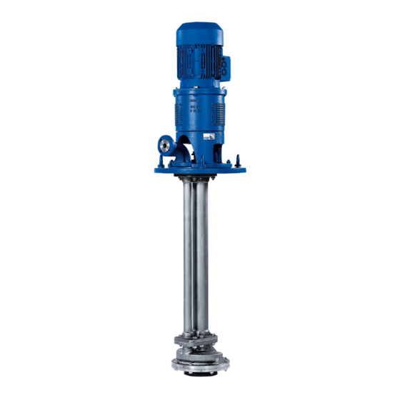
- Page 1 Vertical Shaft Submersible Pump for the Chemical Industry CTN / CTN-H Installation/Operating Manual...
- Page 2 Legal information/Copyright Installation/Operating Manual CTN / CTN-H Original operating manual All rights reserved. The contents provided herein must neither be distributed, copied, reproduced, edited or processed for any other purpose, nor otherwise transmitted, published or made available to a third party without the manufacturer's express written consent.
-
Page 3: Table Of Contents
Permissible forces and moments at the pump nozzles.............. 22 5.4.3 Auxiliary connections......................... 23 Enclosure/insulation ............................ 23 Aligning the pump and motor ........................ 24 Electrical connection ............................ 24 5.7.1 Setting the time relay ........................ 24 5.7.2 Connecting the motor ........................ 25 Checking the direction of rotation........................ 25 CTN / CTN-H 3 of 76... - Page 4 Recommended spare parts stock for 2 years' operation to DIN 24296 .......... 58 7.7.3 Interchangeability of pump components.................. 59 Trouble-shooting.......................... 60 Related Documents .......................... 62 General assembly drawing with list of components .................. 62 9.1.1 CTN.............................. 62 9.1.2 CTN-H.............................. 65 9.1.3 CTN with oil-lubricated thrust bearings ................... 68 CTN / CTN-H 4 of 76...
- Page 5 Contents EU Declaration of Conformity ...................... 71 Certificate of Decontamination...................... 72 Index .............................. 73 CTN / CTN-H 5 of 76...
-
Page 6: Glossary
Pool of pumps Customers/operators’ pumps which are purchased and stored regardless of their later use. Pump Machine without drive, additional components or accessories Pump set Complete pump set consisting of pump, drive, additional components and accessories CTN / CTN-H 6 of 76... -
Page 7: General
In the event of damage, immediately contact your nearest KSB Service centre to maintain the right to claim under warranty. 1.2 Installation of partly completed machinery To install partly completed machinery supplied by KSB refer to the sub-sections under Servicing/Maintenance. -
Page 8: Key To Safety Symbols/Markings
In conjunction with one of the signal words this symbol indicates a hazard involving electrical voltage and identifies information about protection against electrical voltage. Machine damage In conjunction with the signal word CAUTION this symbol indicates a hazard for the machine and its functions. CTN / CTN-H 8 of 76... -
Page 9: Safety
Deficits in knowledge must be rectified by means of training and instruction provided by sufficiently trained specialist personnel. If required, the operator can commission the manufacturer/supplier to train the personnel. Training on the pump (set) must always be supervised by technical specialist personnel. CTN / CTN-H 9 of 76... -
Page 10: Consequences And Risks Caused By Non-Compliance With This Manual
▪ Only perform work on the pump set when it has been disconnected from the power supply (de-energised). ▪ The pump (set) must have cooled down to ambient temperature. ▪ Pump pressure must have been released and the pump must have been drained. CTN / CTN-H 10 of 76... -
Page 11: Unauthorised Modes Of Operation
The temperature class specifies the maximum permissible temperature at the surface of the pump set during operation. For the permissible operating temperature of the pump in question refer to the data sheet. CTN / CTN-H 11 of 76... -
Page 12: Monitoring Equipment
If the pump is to be operated at a higher temperature, if there is no data sheet or if the pump is part of a pool of pumps, contact KSB for the maximum permissible operating temperature. 2.9.3 Monitoring equipment The pump (set) must only be operated within the limits specified in the data sheet and on the name plate. -
Page 13: Transport/Temporary Storage/Disposal
1. On transfer of goods, check each packaging unit for damage. 2. In the event of in-transit damage, assess the exact damage, document it and notify KSB or the supplying dealer and the insurer about the damage in writing immediately. -
Page 14: Return To Supplier
2. Separate and sort the pump materials, e.g. by: - Metals - Plastics - Electronic waste - Greases and other lubricants 3. Dispose of materials in accordance with local regulations or in another controlled manner. CTN / CTN-H 14 of 76... -
Page 15: Description Of The Pump (Set)
▪ Vertical shaft submersible pump for the chemical industry CTN Vertical pump for handling chemically aggressive fluids with a low solids content. CTN-H Vertical pump for handling fluids which must not be allowed to cool down during processing. 4.2 Designation Example: CTN - C H 40 - 250 / 2 Table 5: Key to the designation... - Page 16 Table 9: Optional: oil-lubricated thrust bearings (rolling element bearing) Sizes Bearing size 25/40/50 1 x 6312 DIN 625 80/100 2 x 7312 BUA DIN 628 125/150 2 x 7315 BUA DIN 628 200/250 2 x 7318 BUA DIN 628 CTN / CTN-H 16 of 76...
-
Page 17: Configuration And Function
(10) which provides the boundary for the hydraulic system. The shaft passage through the soleplate (7) is sealed to atmosphere with a shaft seal (1). Depending on the installation depth, the shaft assembly (9) can either consist of a single shaft or CTN / CTN-H 17 of 76... -
Page 18: Noise Characteristics
Surface sound pressure level as per ISO 3744 and EN 12639 valid for pump operation in the Q/Qopt = 0.8 -1.1 range and for non-cavitating operation.If noise levels are to be guaranteed: Add +3 dB for measuring and constructional tolerance. Increase for 60 Hz operation: 3500 rpm +3 dB, 1750 rpm +1 dB, 1160 rpm ±0 dB CTN / CTN-H 18 of 76... -
Page 19: Dimensions And Weights
4 Description of the Pump (Set) 4.8 Dimensions and weights For dimensions and weights please refer to the general arrangement drawing/outline drawing of the pump/pump set. CTN / CTN-H 19 of 76... -
Page 20: Installation At Site
After mounting the drive on the pump, check the clearance between the two coupling halves on the basis of the general arrangement drawing. If the clearance is too large, reduce the distance between the coupling halves. Check the radial alignment. Fig. 4: Checking the coupling alignment Gauge CTN / CTN-H 20 of 76... -
Page 21: Piping
3. Check that the inside of the pump is free from any foreign objects. Remove any foreign objects. 4. Connect the pump nozzles to the piping. CTN / CTN-H 21 of 76... -
Page 22: Permissible Forces And Moments At The Pump Nozzles
The data on forces and moments apply to static pipelines only. If the limits are exceeded, they must be checked and verified. If a computerised strength analysis is required, please contact KSB. Table 11: Permissible forces and moments acting on the flanged bend... -
Page 23: Auxiliary Connections
Risk of potentially explosive atmosphere due to insufficient venting Explosion hazard! ▷ Ensure adequate venting of the space in the bearing bracket lantern/drive lantern. ▷ Never close or cover the perforations of the contact guard on the drive lantern (e.g. with insulation). CTN / CTN-H 23 of 76... -
Page 24: Aligning The Pump And Motor
5.7.1 Setting the time relay CAUTION Switchover between star and delta on three-phase motors with star-delta starting takes too long. Damage to the pump (set)! ▷ Keep switch-over intervals between star and delta as short as possible. CTN / CTN-H 24 of 76... -
Page 25: Connecting The Motor
Damage to the pump! ▷ Refer to the arrow indicating the direction of rotation on the pump. ▷ Check the direction of rotation. If required, check the electrical connection and correct the direction of rotation. CTN / CTN-H 25 of 76... - Page 26 The motor's direction of rotation must match the arrow indicating the direction of rotation on the pump. 3. If the motor is running in the wrong direction of rotation, check the electrical connection of the motor and switchgear, if any. CTN / CTN-H 26 of 76...
-
Page 27: Commissioning/Start-Up/Shutdown
Grease-lubricated bearings Grease-lubricated bearings have been packed with grease. Oil-lubricated bearings Fill the bearing bracket with lubricating oil. Oil quality see (ð Section 7.2.3.2.2, Page 42) Oil quantity see (ð Section 7.2.3.2.3, Page 42) ü The constant level oiler is screwed into the upper tapping hole of the bearing bracket. CTN / CTN-H 27 of 76... -
Page 28: Shaft Seal
Double mechanical seal Prior to starting up the pump, apply barrier pressure as specified in the general arrangement drawing. External liquid feed Apply the quantities and pressures specified in the data sheet and the general arrangement drawing. CTN / CTN-H 28 of 76... -
Page 29: Priming And Venting The Pump
3. Check that the coupling and shaft can easily be rotated by hand. 4. Re-mount the contact guard. 5. Check the distance between coupling and contact guard. The coupling and contact guard must not come into contact. CTN / CTN-H 29 of 76... -
Page 30: Water Cooling
6.1.7 Cooling/heating the shaft seal The shaft seal chamber, if any, can be cooled. To dissipate the generated heat, a fan impeller can be fitted by KSB above the shaft seal. If necessary, the shaft seal chamber can also be heated. - Page 31 1.4571 Pressure Temperature Pressure Temperature [bar] [°C] [bar] [°C] 25/40/50 18.0 14.0 80/100 15.0 12.0 125/150 12.0 12.0 200/250 Flanged bend The flanged bend can also be heated as part of a special design. CTN / CTN-H 31 of 76...
-
Page 32: Heating Up/Keeping Warm The Pump (Set)
▷ Eliminate the causes before returning the pump set to service. ü The system piping has been cleaned. ü In a dry installation configuration, the pump and suction line have been vented and primed with the fluid to be handled. CTN / CTN-H 32 of 76... -
Page 33: Checking The Shaft Seal
ü Also ensure quench liquid supply is ON during pump standstill. 1. Close the shut-off element in the discharge line. 2. Switch off the motor and make sure the pump set runs down smoothly to a standstill. CTN / CTN-H 33 of 76... -
Page 34: Operating Limits
(e.g. fill level monitoring). 6.2.1 Ambient temperature CAUTION Operation outside the permissible ambient temperature Damage to the pump (set)! ▷ Observe the specified limits for permissible ambient temperatures. Observe the following parameters and values during operation: CTN / CTN-H 34 of 76... -
Page 35: Frequency Of Starts
If necessary, the minimum flow must be increased. Minimum permissible flow rate Flow rate at best efficiency point Maximum permissible flow rate CTN / CTN-H 35 of 76... -
Page 36: Shutdown/Storage/Preservation
It is advisable to then close the pump nozzles (e.g. with plastic caps or similar). 3. Oil or grease all blank parts and surfaces of the pump (with silicone-free oil and grease, food-approved if required) to protect them against corrosion. Observe the additional instructions. (ð Section 3.3, Page 13) CTN / CTN-H 36 of 76... -
Page 37: Returning To Service
▷ As soon as the work is completed, properly re-install and re-activate any safety- relevant devices and protective devices. NOTE If the equipment has been out of service for more than one year, replace all elastomer seals. CTN / CTN-H 37 of 76... -
Page 38: Servicing/Maintenance
Fluids handled, consumables and supplies which are hot and/or pose a health hazard Risk of injury! ▷ Observe all relevant laws. ▷ When draining the fluid take appropriate measures to protect persons and the environment. ▷ Decontaminate pumps which handle fluids posing a health hazard. CTN / CTN-H 38 of 76... -
Page 39: Servicing/Inspection
NOTE All maintenance work, service work and installation work can be carried out by KSB Service or authorised workshops. For contact details please refer to the enclosed "Addresses" booklet or visit "www.ksb.com/contact" on the Internet. -
Page 40: Inspection Work
Excessive temperatures caused by friction, impact or frictional sparks Explosion hazard! Fire hazard! Damage to the pump set! ▷ Regularly check the coupling guard, plastic components and other guards of rotating parts for deformation and sufficient distance from rotating parts. CTN / CTN-H 40 of 76... -
Page 41: Lubrication And Lubricant Change Of Thrust Bearings (Rolling Element Bearings)
Explosion hazard! Fire hazard! Damage to the pump set! ▷ Regularly check the condition of the lubricant. 7.2.3.1 Grease lubrication The bearings are supplied packed with high-quality lithium-soap grease. CTN / CTN-H 41 of 76... - Page 42 2 x 7312 BUA DIN 628 5200 hours if n = 960 rpm At least once a year For ambient temperatures below -10 °C use a different suitable type of lubricating oil. Contact KSB. CTN / CTN-H 42 of 76...
-
Page 43: Radial Bearings
7.4 Dismantling the pump set 7.4.1 General information/Safety regulations WARNING Unqualified personnel performing work on the pump (set) Risk of injury! ▷ Always have repair work and maintenance work performed by specially trained, qualified personnel. Including constant-level oiler CTN / CTN-H 43 of 76... -
Page 44: Preparing The Pump Set
Watch the sealing elements. 6. Lift the pump and allow it to drain. 7.4.3 Dismantling the motor 1. Disconnect the motor from the power supply. 2. Unscrew hexagon nuts 920.11. Remove the motor with the coupling half. CTN / CTN-H 44 of 76... -
Page 45: Dismantling The Thrust Bearings
1. Remove ring 500.12 with grub screw 904.32 from shaft protecting sleeve 524.02. 2. Undo hexagon nuts 920.09. Remove seal cover 471.09. 3. Pull complete mechanical seal 433 with shaft protecting sleeve 524.02 off drive shaft 213. 4. Dismantle stuffing box housing 451.02. CTN / CTN-H 45 of 76... -
Page 46: Dismantling The Hydraulic System
7.4.7 Removing the pipe assembly and shaft assembly ü The notes and steps stated in (ð Section 7.4.1, Page 43) bis (ð Section 7.4.6, Page 46) have been observed/carried out. ü On heatable designs (CTN-H), the pipes 710.23/.24/.25/.26 with pipe unions 731.18/.37/.38/.39/.40/.41 have been dismantled. 1. Undo bolts 901.32 and nuts 920.32. -
Page 47: Dismantling The Bearing Sleeves
If this proves difficult, turn off the bearing sleeve using a lathe or split it open along its length using an abrasive cutting machine. CTN special design Bearing sleeve 529.01/03 fastened with parallel pin and grub screw ü The notes and steps stated in (ð Section 7.4.1, Page 43) bis (ð Section 7.4.7, Page 46) have been observed/carried out. -
Page 48: Dismantling The Bearing Bush
Sequence Always reassemble the pump in accordance with the corresponding general assembly drawing. Sealing elements ▪ Gaskets – Always use new gaskets, making sure that they have the same thickness as the old ones. CTN / CTN-H 48 of 76... -
Page 49: Fitting The Bearing Sleeve
ü The individual parts have been placed in a clean and level assembly area. ü All dismantled parts have been cleaned and checked for wear. ü Any damaged or worn parts have been corrected or replaced with original spare parts. ü The sealing surfaces have been cleaned. CTN / CTN-H 49 of 76... -
Page 50: Assembling The Pipe Assembly And Shaft Assembly
1. Slide the bearing sleeve onto the shaft and secure with grooved pin 561.18 or hexagon head bolt 900.18. 2. CTN: The grooved pins 561.21/.22 must engage in the recess of the pipe assembly when installing bearing housing 350.04. CTN-H: The grooved pins 561.21/.22 must engage in the recess of the pipe assembly when installing centring ring 511. -
Page 51: Reassembly Of Hydraulic System
7 Servicing/Maintenance 6. Insert bearing housing 350.04 with bearing bush 545.03, grooved pin 561.22 and O-Ring 412.10 (if applicable) into the recess in the pipe assembly (not for CTN- 7. If pipe assembly 71-9.02 is fitted, repeat steps 1 to 6. -
Page 52: Fitting The Shaft Seal
904.32. CAUTION Fastening the adjusting ring to the shaft Damage to the mechanical seal! ▷ Secure the adjusting ring to the shaft with grub screw after setting the axial impeller clearance. (ð Section 7.5.6, Page 55) and (ð Section 7.5.7, Page 57) CTN / CTN-H 52 of 76... - Page 53 The gland packing has no contact with the fluid handled and only seals against splashes and low gas pressure. Fig. 8: Dimensions of the packing chamber/Number of packing rings; 1 = Design without shaft protecting sleeve, 2 = Design with shaft protecting sleeve CTN / CTN-H 53 of 76...
- Page 54 4. Insert plunger (3). The bottom screw must face outwards. 5. Turn the upper section (2) four turns into the lower section (4). 6. Tighten counter nut (1) on the edge of the lower section. CTN / CTN-H 54 of 76...
-
Page 55: Assembling Thrust Bearings
Adjusting the axial impeller clearance CTN, CTN-H The impeller is centred in the volute casing, i.e. the axial distance between the impeller and the suction cover or the impeller and the volute casing (for a single- stage pump) or the stage casing (for a two-stage pump) is the same. - Page 56 Check that the rotor can easily be rotated by hand, without causing any grinding noises. 4. Align the coupling. (ð Section 5.3, Page 20) CTN with oil-lubricated thrust bearings NOTE The overall axial clearance of the pump rotor is determined by lowering and pulling the rotor up using the centring sleeve.
-
Page 57: Preloading The Mechanical Seal
These values are determined on the basis of a friction coefficient of μ = 0.12. After repeated tightening of the threads and in case of good lubrication the values shall be reduced by 15 to 20 %. CTN / CTN-H 57 of 76... -
Page 58: Recommended Spare Parts Stock For 2 Years' Operation To Din 24296
▪ Shipping address ▪ Mode of dispatch (freight, mail, express freight, air freight) 7.7.2 Recommended spare parts stock for 2 years' operation to DIN 24296 Table 28: Quantity of spare parts for recommended spare parts stock for CTN, CTN-H Part No. Description... -
Page 59: Interchangeability Of Pump Components
16 - 16 9 9 4 4 16 4 4 4 4 4 4 4 4 10 6 9 4 6 For identical lengths If fitted For identical motors Only for identical seal types For identical nominal diameters CTN / CTN-H 59 of 76... -
Page 60: Trouble-Shooting
If problems occur that are not described in the following table, consultation with the KSB customer service is required. A Pump delivers insufficient flow rate B Motor is overloaded... - Page 61 ✘ ✘ - Defective bearing(s) Replace. ✘ ✘ Flow rate is too low. Increase the minimum flow rate. ✘ - Air intake at pump inlet Increase the minimum fluid level. ✘ - System-induced vibrations CTN / CTN-H 61 of 76...
-
Page 62: Related Documents
9 Related Documents 9 Related Documents 9.1 General assembly drawing with list of components 9.1.1 CTN Fig. 12: CTN general assembly drawing CTN / CTN-H 62 of 76... - Page 63 Not shown Only for two-stage pumps If only one shaft is fitted: For large installation depths, the shaft assembly consists of a pump shaft and drive shaft or pump shaft, intermediate shaft(s) and drive shaft CTN / CTN-H 63 of 76...
- Page 64 72-1 Flanged bend with gasket 400.17 852.01 Threaded coupling 893.02 Soleplate with joint ring 411.47, disc 550.17, eyebolt 900.03, studs 902.05/.12/.30/.31, hexagon nuts 920.05/.12/.30/.31 71-9.01/.02/.03 etc. for several pipe assemblies, counted from the pump CTN / CTN-H 64 of 76...
-
Page 65: Ctn-H
9 Related Documents 9.1.2 CTN-H Fig. 13: CTN-H general assembly drawing CTN / CTN-H 65 of 76... - Page 66 561.01/.02, grub screw 904.03/.04 502.03/.04 Casing wear ring with grooved pin 561.07/.08, grub screw 904.34/.35 Centring ring with grooved pin 561.22 524.02 Shaft protecting sleeve with O-ring 412.32, grub screw 904.14, key 940.07 Spacer sleeve CTN / CTN-H 66 of 76...
- Page 67 400.17, hexagon head bolt 901.32, hexagon nut 920.32 710.23-.26 Pipe with pipe union 731.18/.37/.38/.39/.40/.41 72-1 Flanged bend with gasket 400.17 Threaded coupling 893.02 Soleplate with disc 550.17, eyebolt 900.03, studs 902.05/.12/.30/.31, hexagon nuts 920.05/.12/.30/.31 CTN / CTN-H 67 of 76...
-
Page 68: Ctn With Oil-Lubricated Thrust Bearings
9 Related Documents 9.1.3 CTN with oil-lubricated thrust bearings Fig. 14: General assembly drawing for CTN with oil-lubricated thrust bearings CTN / CTN-H 68 of 76... - Page 69 920.22, lockwasher 931.02, key 940.01/.02/.03/.11 Pump shaft with cap nut 920.22, lockwasher 931.02, key 940.01/.03 Intermediate shaft Drive shaft with key 940.02/.11 230.01/.02 Impeller For two-stage pumps, specify whether for 1st or 2nd stage 320.02 Rolling element bearing CTN / CTN-H 69 of 76...
- Page 70 400.17, hexagon head bolt 901.32, hexagon nut 920.32 72-1 Flanged bend with gasket 400.17 852.01 Threaded coupling 893.02 Soleplate with disc 550.17, eyebolt 900.03, studs 902.05/.12/.30/.31, hexagon nuts 920.05/.12/.30/.31 Bearing nut with socket head cap screw 914.12 CTN / CTN-H 70 of 76...
- Page 71 67227 Frankenthal (Germany) The manufacturer herewith declares that the product: CTN, CTNH KSB order number: ....................▪ is in conformity with the provisions of the following Directives as amended from time to time: – Pump (set): Machinery Directive 2006/42/EC The manufacturer also declares that ▪...
- Page 72 We confirm that the above data and information are correct and complete and that dispatch is effected in accordance with the relevant legal provisions....................................Place, date and signature Address Company stamp Required fields CTN / CTN-H 72 of 76...
- Page 73 Frequency of starts 35 Safety 9 Safety awareness 10 Gland packing 33 Scope of supply 18 Grease lubrication Shutdown 33, 37 Grease quality 42 Soleplate 18 Spare part Ordering spare parts 57 Heating 31 Spare parts stock 58 Heating speed 32 Special accessories 18 Heating up 32 Start-up 32 Storage 14, 37 CTN / CTN-H 73 of 76...
- Page 74 Index Temperature difference 32 Temperature limits 11, 12 Tightening torques 57 Transport 13 Warnings 8 Warranty claims 7 Water cooling 30 CTN / CTN-H 74 of 76...
- Page 76 KSB SE & Co. KGaA Johann-Klein-Straße 9 • 67227 Frankenthal (Germany) Tel. +49 6233 86-0 www.ksb.com...
Need help?
Do you have a question about the CTN and is the answer not in the manual?
Questions and answers