
Subscribe to Our Youtube Channel
Summary of Contents for REXROTH IndraControl VAM 21.1
- Page 1 IndraControl VAM 15.1/21.1 Machine Control Panels Operating Instructions Edition 02 R911346746...
- Page 2 © Bosch Rexroth AG 2016 This document, as well as the data, specifications and other information set forth in it, are the exclusive property of Bosch Rexroth AG. It may not be repro- duced or given to third parties without its consent.
-
Page 3: Table Of Contents
Machine Control Panels Bosch Rexroth AG Table of Contents Table of Contents Page About this documentation..............1 About this documentation..............1 Product identification and scope of delivery........Product identification................2 Scope of delivery................... 3 Use of the safety instructions..............3 Structure of the safety instructions............ - Page 4 10.4.1 Front view.................... 22 10.4.2 Side view..................... 22 10.4.3 Top view....................10.4.4 Rear view..................... 23 10.5 Housing dimensions of the IndraControl VAM 21.1......24 10.5.1 Front view.................... 24 10.5.2 Side view..................... 24 10.5.3 Top view....................10.5.4 Rear view..................... 25 10.6 Electric connection................
- Page 5 12.2.2 Rear side..................... 12.2.3 Front view of the machine control panel, overview......33 12.2.4 Front view of the machine control panel IndraControl VAM 15.1..34 12.2.5 Front view of the machine control panel IndraControl VAM 21.1..34 12.3 Describing operating elements............
- Page 6 Bosch Rexroth AG Machine Control Panels Table of Contents Page Error causes and troubleshooting............Maintenance..................45 14.1 General information................14.2 Tightening torques and stripping length..........14.3 Cleaning notes..................47 14.4 Regular maintenance tasks..............47 Ordering information................47 15.1 Accessories and spare parts...............
-
Page 7: About This Documentation
Machine Control Panels Bosch Rexroth AG About this documentation 1 About this documentation 1.1 About this documentation Overview on target groups and product phases In the following illustration, the framed activities, product phases and target groups refer to the present documentation. -
Page 8: Product Identification And Scope Of Delivery
Please email your feedback on the documentations to Feed- back.Documentation@boschrexroth.de. Directly insert comments in the elec- tronic PDF document and send the PDF file to Bosch Rexroth. 2 Product identification and scope of delivery 2.1 Product identification The type plate is located on the rear side or at the side of the device. -
Page 9: Scope Of Delivery
Machine Control Panels Bosch Rexroth AG Use of the safety instructions 2.2 Scope of delivery Machine control panel ● 3 Use of the safety instructions 3.1 Structure of the safety instructions The safety instructions are structured as follows: Consequences and... -
Page 10: Symbols Used
Prior to the installation and commissioning of the device, refer to the device documentation. krax 4 Intended use The machine control panels of the type IndraControl VAM 15.1/VAM 21.1 by Bosch Rexroth are intended for operating control units. 4/53 DOK-SUPPL*-VAM*15*21*1-IT02-EN-P... -
Page 11: Spare Parts, Accessories And Wear Parts
Machine Control Panels Bosch Rexroth AG Spare parts, accessories and wear parts NOTICE Risk of damaging the device if not expressly sta- ted accessories, mounting parts and other com- ponents, cables, lines and software and firm- ware are used The machine control panels may be used only as intended and with the accesso- ries, mounting parts and other components specified in this documentation. -
Page 12: Ambient Conditions
Bosch Rexroth AG Machine Control Panels Ambient conditions Ordering code Part number Description RKB0013/00,35 (*******-*******-*******) R911317800 Bus cable, length 0.35 m, RJ45/RJ45 plug RKB0013/00,55 (*******-*******-*******) R911317801 Bus cable, length 0.55 m, RJ45/RJ45 plug RKB0013/001,0 (*******-*******-*******) R911340679 Bus cable, length 1.0 m, RJ45/RJ45 plug RKB0013/002,0 (*******-*******-*******) R911338023 Bus cable, length 2.0 m, RJ45/RJ45 plug... - Page 13 Machine Control Panels Bosch Rexroth AG Ambient conditions Ambient condi- In operation Transport Storage tions Humidity Min. relative humidity: Min. relative humidity: 5 % Min. relative humidity: 5 % Max. relative humidity: 75 % Max. relative humidity: Max. relative humidity: 85 % Min.
-
Page 14: Technical Data
(also re- fer to DIN EN 55022). 7 Technical data 7.1 Basic device IndraControl VAM 15.1 IndraControl VAM 21.1 Degree of protection IP 54 (front panel) Front foil color RAL 7024 graphite gray Dimensions (W ×... -
Page 15: E-Stop Button
Machine Control Panels Bosch Rexroth AG Technical data IndraControl VAM 15.1/VAM 21.1 Voltage supply Electrically isolated Logic supply U 24 V DC (19.2 V to 30 V), PELV Use for example the 24 V industrial power supply unit VAP01.1H-W23-024-010-NN with the part... -
Page 16: Machine Pushbuttons
Bosch Rexroth AG Machine Control Panels Technical data B10d value mushroom button Mechanics: B10d = 600,000 (acc. to the manufacturer) Assumption: B10d = 2 × B10 Fault exclusion at < 6050 cycles B10d value auxiliary contact N/C contact Electrics: B10d = 10,000,000 (acc. to the manufacturer) Assumption: B10d = 2 ×... -
Page 17: Standards
Machine Control Panels Bosch Rexroth AG Standards 8 Standards 8.1 Standards used Standard Meaning EN 60204-1 Safety of machinery - Electrical equipment of machines EN 61000-6-4 Generic standards - Emission standard (industrial environments) EN 61000-6-2 Generic standards – Noise immunity (industrial environments) -
Page 18: Ul/Csa Certified
Bosch Rexroth AG Machine Control Panels Standards Standard Title Edition IEC 61000-6-4 Electromagnetic compatibility (EMC) 2011 Part 6-4: Generic standards – Emission standard for indus- trial environments (EN 61000-6-4: 2007 + A1:2011) IEC 61000-6-2 Electromagnetic compatibility (EMC) 2006 + B1:2011 Part 6-2: Generic standards –... -
Page 19: Connections
Machine Control Panels Bosch Rexroth AG Connections 9 Connections 9.1 Connector panel X7E2 X2I1 X2I1 OPEN OPEN LED H3 1 2 3 4 5 6 7 8 1 2 3 4 5 6 7 8 LED H4 X2I2 X2I2 X7E1... -
Page 20: X1S2: Voltage Tapping For Front Elements
Bosch Rexroth AG Machine Control Panels Connections 9.3 X1S2: Voltage tapping for front elements 4-pin Weidmüller plug X1S2 provides the voltage U to supply operating elements and light indicators on the IndraControl VAM 15.1/VAM 21.1 front panel. Plugs Signal Meaning... -
Page 21: X2I1, X2I2, X2O1, X2O2: Digital 24 V Inputs And Outputs
Machine Control Panels Bosch Rexroth AG Connections 9.5 X2I1, X2I2, X2O1, X2O2: Digital 24 V inputs and outputs 9.5.1 General information The IndraControl VAM 15.1/VAM 21.1 component group provides 16 digital 24 V inputs and 16 digital 24 V outputs. The plugs of the inputs and outputs are loca- ted on the logic circuit board. -
Page 22: Characteristics Of The Digital Inputs
Bosch Rexroth AG Machine Control Panels Connections Plugs Name on the Signal Meaning circuit board X2O2 Digital 24 V outputs Q 8 - Q 15 Tab. 9-5: Pin assignment X2I1, X2I2, X2O1, X2O2 DANGER Dangerous movements due to plugging or un-... -
Page 23: X81: Connection For External Hand-Held Terminal
Machine Control Panels Bosch Rexroth AG Connections Reverse voltage protection Only guaranteed without load connection Defect of the component caused by: Polarity reversal with simultaneous short circuit ● of the output lines Polarity reversal with simultaneous connection ● of externally polarized suppressor diodes at the output lines Applying of external voltage >... -
Page 24: X81: Pin Assignment (25-Pin Female Connector Strip, D-Sub)
Bosch Rexroth AG Machine Control Panels Connections The address allocation is described chapter "Bit string for external hand-held terminal" on page 9.6.2 X81: Pin assignment (25-pin female connector strip, D-Sub) Fig. 9-3: Pin assignment X81 Plugs Signal Meaning +24 V... -
Page 25: X82: Connection For Internal Handwheel
Machine Control Panels Bosch Rexroth AG Connections Handwheel supply 5 V DC ± 5 % Current consumption, handwheel 200 mA max. Maximum cable length Approx. 5 m (depending on handwheel) Cable type Twisted pair, separately shielded Inputs 12 × 24 V input... -
Page 26: X3U1: Service Interface
Machine Control Panels Mounting, demounting and electric installation 9.8 X3U1: Service interface The interface "X3U1" is a service interface (mini USB socket) only intended for the Bosch Rexroth Service (also refer to chapter 17 "Service and support" on page 49). -
Page 27: Mounting Cut-Out
Mounting cut-out (dimension A, B) Fig. 10-2: Dimensions of the mounting cut-out Machine control panel Mounting cut-out Dimension A Dimension B IndraControl VAM 15.1 152 +1/-0 403 +1/-0 IndraControl VAM 21.1 151 +1/-0 330 +1/-0 Tab. 10-1: Mounting cut-out in mm 21/53 DOK-SUPPL*-VAM*15*21*1-IT02-EN-P... -
Page 28: Housing Dimensions Of The Indracontrol Vam 15.1
Bosch Rexroth AG Machine Control Panels Mounting, demounting and electric installation 10.4 Housing dimensions of the IndraControl VAM 15.1 10.4.1 Front view Fig. 10-3: IndraControl VAM 15.1, front view 10.4.2 Side view Fig. 10-4: IndraControl VAM 15.1, side view 22/53... -
Page 29: Top View
Machine Control Panels Bosch Rexroth AG Mounting, demounting and electric installation 10.4.3 Top view Fig. 10-5: IndraControl VAM 15.1, top view 10.4.4 Rear view Fig. 10-6: IndraControl VAM 15.1, rear view 23/53 DOK-SUPPL*-VAM*15*21*1-IT02-EN-P... -
Page 30: Housing Dimensions Of The Indracontrol Vam 21.1
Bosch Rexroth AG Machine Control Panels Mounting, demounting and electric installation 10.5 Housing dimensions of the IndraControl VAM 21.1 10.5.1 Front view Fig. 10-7: IndraControl VAM 21.1, front view 10.5.2 Side view Fig. 10-8: IndraControl VAM 21.1, side view 24/53... -
Page 31: Top View
Machine Control Panels Bosch Rexroth AG Mounting, demounting and electric installation 10.5.3 Top view Fig. 10-9: IndraControl VAM 21.1, top view 10.5.4 Rear view Fig. 10-10: IndraControl VAM 21.1, rear view 25/53 DOK-SUPPL*-VAM*15*21*1-IT02-EN-P... -
Page 32: Electric Connection
Bosch Rexroth AG Machine Control Panels Mounting, demounting and electric installation 10.6 Electric connection 10.6.1 General information DANGER Danger without safe separation! The 24 V DC input voltages must comply with the requirements of the "safe ● separation"! Plug and remove the plug connection only if there is no voltage! ●... -
Page 33: Connection Diagram
Machine Control Panels Bosch Rexroth AG Mounting, demounting and electric installation 10.6.3 Connection diagram Overvoltage category I Terminal block UK6-FSI/6 with automatic cut-out TCP 2 A (PHOENIX CONTACT) is recommended X1S1 6 mm ² (blue) X1S1 6 mm ² (blue) FE = Functional earth ground 10 mm ²... -
Page 34: Notes On Current And Voltage Supply
Bosch Rexroth AG Machine Control Panels Mounting, demounting and electric installation To ensure a proper operation of the EMC suppressor circuits of the IndraControl VAM 15.1/VAM 21.1 according to the guidelines, the functional earth has to be connected! 10.6.5 Notes on current and voltage supply... -
Page 35: Sercos Iii Interfaces
Machine Control Panels Bosch Rexroth AG Mounting, demounting and electric installation "4" can be used for example as signal contact for the state evaluation of the E- STOP button via a PLC. Only 24 V (protective extra-low voltage) may only be connected to the E-STOP button! Fig. -
Page 36: Connection For External Hand-Held Terminal
Bosch Rexroth AG Machine Control Panels Commissioning 10.6.10 Connection for external hand-held terminal General information Next to the inputs for the handwheel of the hand-held terminal (A, /A, B, /B), 12 inputs (IN0 – IN11) are available for the keys of the hand-held terminal. The keys are supplied via the "+24 V"... -
Page 37: Commissioning Sercos Iii
The IndraControl VAM 15.1 width corresponds to the IndraControl VPP 15.3 panel PC width or the IndraControl VDP 15.3 width. The IndraControl VAM 21.1 width corresponds to the IndraControl VPP 21.3 panel PC width or the IndraControl VDP 21.3 in vertical mounting position. -
Page 38: Standard Variantsindracontrol Vam 15.1/Vam 21.1
Bosch Rexroth AG Machine Control Panels Device description 12.2 Standard variantsIndraControl VAM 15.1/VAM 21.1 12.2.1 Overview on standard variants The IndraControl VAM 15.1/VAM 21.1 machine control panels are available in dif- ferent standard variants: Keypad with keys and Further elements... -
Page 39: Front View Of The Machine Control Panel, Overview
Machine Control Panels Bosch Rexroth AG Device description 16 digital 24 V outputs ● Voltage supply connections ● Functional earth connection ● Voltage tapping for front elements ● Two RJ45 sockets for Sercos III ● Service interface ● LEDs for status displays ●... -
Page 40: Front View Of The Machine Control Panel Indracontrol Vam 15.1
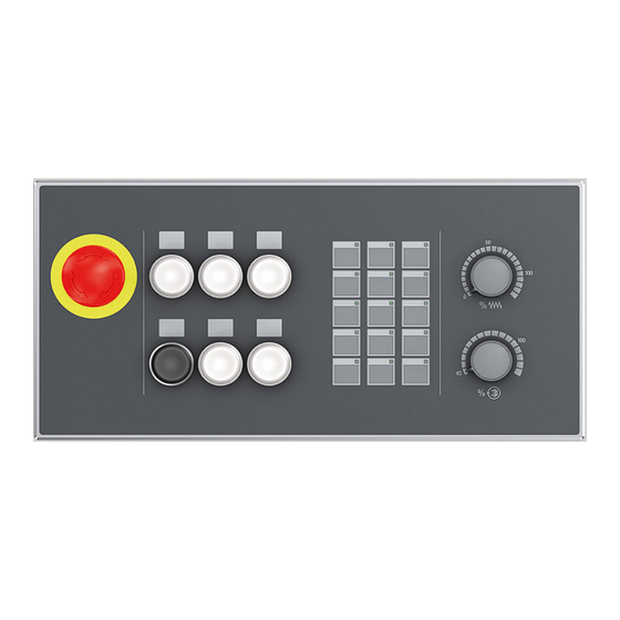
12.2.4 Front view of the machine control panel IndraControl VAM 15.1 Fig. 12-2: Front view of the IndraControl VAM 15.1 12.2.5 Front view of the machine control panel IndraControl VAM 21.1 Fig. 12-3: Front view of the IndraControl VAM 21.1 12.3 Describing operating elements... -
Page 41: Labeling Templates For Slide-In Strips
Bosch Rexroth AG Device description 12.3.2 Labeling templates for slide-in strips Please find the labeling templates on the Bosch Rexroth web site or contact your sales representative. The labels for the machine function keys can be created with the templates and can be printed on transparent foil or on paper using a laser printer. -
Page 42: Keypad
Bosch Rexroth AG Machine Control Panels Device description Fig. 12-5: Combined cut-out for a 16 mm or 22.5 mm operating or display element ① Cut-out Fig. 12-6: Position of the cut-out for a 16 mm or 22.5 mm operating or display element 12.3.5 Keypad... -
Page 43: Override Rotary Switch
The 22.5 mm switching elements (① in the following figure) are pro- vided on both the machine control panels IndraControl VAM 15.1 and IndraControl VAM 21.1. The four additional combine pre-cut-outs for 16 mm/22.5 mm switching elements (② in the following figure) are only provided on the IndraControl VAM 15.1. -
Page 44: Operating And Error Display
Bosch Rexroth AG Machine Control Panels Device description Fig. 12-9: 22.5 mm switching elements and combined pre-cut-outs of 16mm/22.5 mm The 22.5 mm switching elements can be wired application-specifically. Switching element Contact equipment Illumination Illuminated pushbutton, white 1 x N/O contact... -
Page 45: Status Displays H1 To H4
Machine Control Panels Bosch Rexroth AG Device description Dig. In. 0 X2I1 X2I2 Dig. In. 15 Dig. Out. 8 Dig. Out. 0 X2O1 X2O2 Dig. Out. 15 Dig. Out. 7 ① Status displays of the digital inputs 0 to 15 ②... - Page 46 Sercos III Firmware) runs without errors Lights orange The internal operating system runs without application. Please contact the Bosch Rexroth Service Flashes orange Check the switch position at the S1 and S2 DIP switches. All switches have to be set to the "open"...
-
Page 47: Status Displays At X7E1 And X7E2
Machine Control Panels Bosch Rexroth AG Device description Sercos III LED - H4 The Sercos III messages are displayed on the LED H4. H4 is a two-colored LED, which lights either red, green or orange in this use case. The meaning of the states corresponds to the valid Sercos III specification. -
Page 48: Override Rotary Switch
Bosch Rexroth AG Machine Control Panels Device description S1.1 S1.2 S1.3 H1.1 H1.2 H1.3 S1.4 S1.5 S1.6 H1.4 H1.5 H1.6 S1.7 S1.8 S1.9 H1.7 H1.8 H1.9 S1.10 S1.11 S1.12 H1.10 H1.11 H1.12 S1.13 S1.14 S1.15 H1.13 H1.14 H1.15 Fig. 12-12: LED and key assignment of the "Keypad TA" module... - Page 49 Machine Control Panels Bosch Rexroth AG Device description The positions of the rotary switches (inputs) of the override module are mapped in the "Override VD" module at the field bus. Gray code table for 24-stage feed override Switch position 0 (min.) 23 (max.)
-
Page 50: Digital 24 V Inputs And Outputs
Bosch Rexroth AG Machine Control Panels Device description Switch position 15 (max.) Tab. 12-9: Gray code table for 16-stage spindle override Bit string for override Override VD Format Feed override BYTE Spindle override BYTE Tab. 12-10: Input assignment of the module "Override VD"... -
Page 51: Internal Handwheel
Machine Control Panels Bosch Rexroth AG Maintenance Bit string for external hand-held terminal Manual Control Format MSB Unit Handwheel WORD 16-bit counter value Button inputs WORD 0 0 0 0 IN11 IN10 IN9 IN8 IN7 IN6 IN5 IN4 IN3 IN2 IN1 IN0 Tab. -
Page 52: Tightening Torques And Stripping Length
Bosch Rexroth AG Machine Control Panels Maintenance Only the maintenance works at the device listed in this chapter are permitted. For further information in the event of repair, please contact the Bosch Rexroth Service. NOTICE Loss of IP degree of protection due to incorrect... -
Page 53: Cleaning Notes
Machine Control Panels Bosch Rexroth AG Ordering information 14.3 Cleaning notes NOTICE The foil surface is dissolved by solvents! Do not use any solvents (e. g. diluents)! ● Do not use high pressure cleaning device! ● 14.4 Regular maintenance tasks Check all plug and terminal connections of the components for proper tight- ●... -
Page 54: Type Code
Bosch Rexroth AG Machine Control Panels Disposal 15.2 Type code Short text column 1 2 3 4 5 6 7 8 9 0 1 2 3 4 5 6 7 8 9 0 1 2 3 4 5 6 7 8 9... -
Page 55: Return
Machine Control Panels Bosch Rexroth AG Service and support 16.2 Return For disposal, our products can be returned free of charge. However, the prod- ucts must be free of remains like oil and grease or other impurities. Furthermore, the products returned for disposal must not contain any undue for- eign substances or components. - Page 56 Bosch Rexroth AG Machine Control Panels Service and support Type plate specifications of the affected products, in particular type codes ● and serial numbers Your contact data (phone and fax number as well as your e-mail address) ● 50/53 DOK-SUPPL*-VAM*15*21*1-IT02-EN-P...
-
Page 57: Index
Characteristics of the digital panel IndraControl VAM 15.1..34 inputs..........16 Front view machine control Characteristics of the digital panel IndraControl VAM 21.1..34 outputs......... 16 Functional earth connection..27 Cleaning notes......47 Fuses........13, 28 Combined cut-out for a 16 mm or 22.5 mm...... - Page 58 Bosch Rexroth AG Machine Control Panels Index Slide-in strips........ 35 Spare parts........5 Intended use........4 Spindle override......37 Internal handwheel....... 45 Standard variants......32 Standards........11 Status displays H1 to H4....39 Keypad........36, 41 Status displays of digital in- Keypad TA........
- Page 59 Machine Control Panels Bosch Rexroth AG Notes...
- Page 60 Bosch Rexroth AG Electric Drives and Controls P.O. Box 13 57 97803 Lohr, Germany Bgm.-Dr.-Nebel-Str. 2 97816 Lohr, Germany Phone +49 9352 18 0 Fax +49 9352 18 8400 www.boschrexroth.com/electrics *R911346746* R911346746 DOK-SUPPL*-VAM*15*21*1-IT02-EN-P...
Need help?
Do you have a question about the IndraControl VAM 21.1 and is the answer not in the manual?
Questions and answers