
Related Manuals for Rohm WPC Qi-compliant Wireless Power Series


Summary of Contents for Rohm WPC Qi-compliant Wireless Power Series
- Page 1 WPC Qi-compliant Wireless Power Series NFC-compatible Wireless Power Transmitter for Automotive Applications BD57121MUF-M Evaluation Board BD57121MUF-EVK-001...
-
Page 2: High Voltage Safety Precautions
[8] Be sure to wear insulated gloves when handling is required during operation. After Use [9] The ROHM Evaluation Board contains the circuits which store the high voltage. Since it stores the charges even after the connected power circuits are cut, please discharge the electricity after using it, and please deal with it after confirming such electric discharge. -
Page 3: Performance Specification
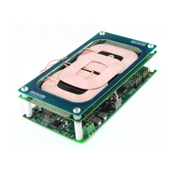
User’s Guide WPC Qi-compliant Wireless Power Series NFC-compatible Wireless Power Transmitter for Automotive Applications BD57121MUF-M Evaluation Board BD57121MUF-EVK-001 BD57121MUF-EVK-001 Evaluation Board is based on the BD57121MUF-M Automotive-grade wireless power transmitter IC. This board integrates the ST25R3914 NFC reader/writer IC from ST Microelectronics to detect the presence of any NFC cards or tags and to prevent damaging of the NFC antennae by the wireless power transfer system. -
Page 4: Evaluation Board
Low Dropout Regulator IC BD00C0AWFP-C Infineon Technologies Buck-Boost DC/DC controller IC TLD5190QV ST Microelectronics NFC Reader/Writer IC ST25R3914 ST Microelectronics Microcontroller STM8AF62A8 Qi Transmitter Coil WT1005690-12F2-A6-G1 ROHM Semiconductor NFC Antenna - (PCB pattern) © 2019 ROHM Co., Ltd. No. 61UG042E Rev.001 2/13 JAN.2019... - Page 5 Buck-Boost BD57121MUF-M DC/DC VBUS54 Full Bridge (3.3V) monitor VDDMCU Pre- ST Micro drive monitor NFC Antenna ST25R3914 Coil Selector COIL1 COIL2 COIL3 Qi Resonant Tank Figure 3. BD57121MUF-EVK-001 Block diagram © 2019 ROHM Co., Ltd. No. 61UG042E Rev.001 3/13 JAN.2019...
-
Page 6: Operation Procedures
(1) 12V, 3A DC power supply (2) BD57121MUF-EVK-001 Evaluation board (this EVK) (3) Qi compliant receivers (Qi compliant Smartphone / Rohm's EVK receiver: BD57015GWL-EVK-002) (4) Load (Electronic load or resistor is prepared as a load on the receiver side, if necessary) - Page 7 End of Power Transfer The transmitter has stopped transferring power because it has received a stop signal from the receiver that is in use. Please check using another receiver if the same phenomenon occurs. © 2019 ROHM Co., Ltd. No. 61UG042E Rev.001 5/13...
-
Page 8: Circuit Diagram
BD57121MUF-EVK-001 User’s Guide Circuit Diagram 1 Figure 5. BD57121MUF-EVK-001 Circuit Diagram (1/2) © 2019 ROHM Co., Ltd. No. 61UG042E Rev.001 6/13 JAN.2019... - Page 9 BD57121MUF-EVK-001 User’s Guide Circuit Diagram 2 Figure 6. BD57121MUF-EVK-001 Circuit Diagram (2/2) © 2019 ROHM Co., Ltd. No. 61UG042E Rev.001 7/13 JAN.2019...
-
Page 10: Bill Of Materials
ROHM 1 kΩ R205, R206 Resistor, Chip, 1/16W 1005 MCR01MZPD1001 ROHM 2Ω R300_NFCF, R301_NFCF Resistor, Chip, 1/10W 1608 MCR03EZPD2R00 ROHM 1 Ω R300, R301 Resistor, Chip, 1/10W 1608 MCR03EZPD1R00 ROHM © 2019 ROHM Co., Ltd. No. 61UG042E Rev.001 8/13 JAN.2019... - Page 11 3225 Y100 27.12 MHz Oscillator, CRYSTAL, 6PF 2016 XRCGB27M120F3A00R0 MURATA RVDDIO, ROSC10, ROSC20, CSER21, Jumper, SOLDER SHORT CSER22, CSER23, CSER24 JUMPER 0Ω J302, J303 Resistor, Chip, 1/16W 1005 MCR01MZPJ000 ROHM © 2019 ROHM Co., Ltd. No. 61UG042E Rev.001 9/13 JAN.2019...
- Page 12 BD57121MUF-EVK-001 User’s Guide Layout 1 Figure 7. Top silk screen, layout (Top View) Figure 8. Bottom silk screen, layout (Top View) Figure 9. TOP Layer layout (Top View) © 2019 ROHM Co., Ltd. No. 61UG042E Rev.001 10/13 JAN.2019...
- Page 13 BD57121MUF-EVK-001 User’s Guide Layout 2 Figure 10. Middle Layer 1 layout (Top View) Figure 11. Middle Layer 2 layout (Top View) Figure 12. Bottom Layer layout (Top View) © 2019 ROHM Co., Ltd. No. 61UG042E Rev.001 11/13 JAN.2019...
-
Page 14: Reference Application Data
Output Power at Rx [W] Figure 13. System Efficiency vs POUT (EPP) Rx: BD57015GWL-EVK-002(ROHM), 12V output Output Power at Rx [W] Figure 14. System Efficiency vs POUT (BPP) Rx: BD57011AGWL (ROHM), 5V output © 2019 ROHM Co., Ltd. No. 61UG042E Rev.001 12/13 JAN.2019... -
Page 15: Revision History
BD57121MUF-EVK-001 User’s Guide Revision history date Revision Changes 16. Jan. 2019 New release © 2019 ROHM Co., Ltd. No. 61UG042E Rev.001 13/13 JAN.2019... - Page 16 Products. ROHM does not grant you, explicitly or implicitly, any license to use or exercise intellectual property or other rights held by ROHM or any other parties. ROHM shall have no responsibility whatsoever for any dispute arising out of the use of such technical information.
Need help?
Do you have a question about the WPC Qi-compliant Wireless Power Series and is the answer not in the manual?
Questions and answers